1
FOOD WASTE
DISPOSERS
GUIDE FOR EASY, TROUBLE-FREE
INSTALLATION,
CARE AND USE.
HOW THIS GUIDE
This guide describes everything you need to know
to install your new food waste disposer, including
care and use information. If you take your time,
follow the instructions and drawings, you should
II
WILL HELP YOU.
have no trouble making a first-rate installation.
NOTE: Read through the entire guide before you
start installation so you can get all the tools and
materials you will need with one trip to the store.
I I! II!1
These
are the tools and
materials
you will need.
These
are the
materials
you
tools
and
may need.
SWITCH 120 amp, rating)/_,_"
_
-
ON-OFFELECTRICAL
AUGER
DRAIN
_
HAMMER
ADJUSTABLE
("CRESCENT")
WRENCH
_
PIPE
WRENCH
HACK
SAW
ELECTRICAL CABLE
CONNECTOR
(1/2inch)
o o I /
DISHWASHER
DRAIN CONNECTIN
PLUMBER'S PULP(
(% lb.)
WP71865
WIRE NUTS
(2 - Size 54)
HOSE CLAMP
(7_ inch)
COPPER
WIRE
(12 or 14 gauge )
/
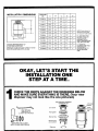
INSTALLATION
DIMENSIONS
A
I
NOTE: Please refer to the
dimensions which match
your disposer model number.
B" - DISTANCE FROM
BOTTOM OF SINK TO
CENTER LINE OF
DISPOSER OUTLET,
ADD 1/2"WHEN STAINLESS
STEEL SINKS ARE USED,
E" - LENG'R,_ OF
DISCHARGE TUBE FROM
CENTER UNE OF
DISPOSER OUTLET TO
END OF DISCHARGE
TUBE.
DRAWING REPRESENTATIVE OF
A FOOD WASTE DISPOSER
IMPORTANT:PLUMB WASTELINE TO PREVENTSTANDING WATER IN DISPOSERMOTOR HOUSING.
"
OKAY, LET'S START THE
INSTALLATION
ONE
STEP AT A TIME.
b
AND
MAKE
IS DRAWINGS
THERE. (your
new
CHECK
THE SURE
PARTSEVER,..YTHING
AGAINST THE
BELOW
disposer may not look hke the one pictured.)
THE MOUNTING ASSEMBLY
CONSISTING OF:
Sink sleeve
_/o_17
(__/'
"WRENCHETTE"
_oie_ing
Fiber gasket
(1/4INCH HEX WRENCH)
Back-up ring
_
_)
SE( F-SERVICE
Mounting ring
and 3 screws
DISCHARGE TUBE, GASKET,
METAL FLANGE AND SCREW(S)
Snap ring
/
°
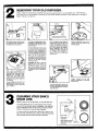
REMOVING YOUR OLD DISPOSER.
FIRST, TURN OFF ELECTRICAL
POWER at the service panel (fuse box or circuit breaker box). If the mounting
is the same as your new disposer's
mounting, you can use the existing mounting. Follow instructions
A through
Step 2, then go on to Step 10.
E,
Screw
i
B.
Use a pipe wrench to disconnect
the drain line where it attaches to
the disposer discharge tube.
Wire
IF YOUR OLD DISPOSER HAS A
DIFFERENT MOUNTING THAN
YOUR NEW ONE, GO ON TO INSTRUCTION C.
If your old disposer has the same
mounting as your new one, insert
the end of your "wrenchetta" or
screwdriver into the right side of
one of the disposer mounting ring
lugs at the top of the disposer.
Then, turn the "wrenchette"
or
screwdriver to the left (counterclockwise) until the lug lines up
with one of the sink mounting
assembly screws.
Nuts
Now, use a screwdriver
to
remove ground wire. Remove the
wire nuts from the power wires.
Separate the disposer
power
wires from the cable wires.
Loosen the screw(s) on the cable
clamp and remove the cable from
the disposer.
Once the disposer is off, turn it
upside down and remove the
electrical plate.
CAUTION: Be sure to hold-the
disposer with one hand while performing this step or it may fall
when the mounting ring is disconnected from the sink mounting assembly. GO TO INSTRUCTION 13.
Finally, remove the old sink
sleeve by pushing it up through
the sink hole.
If your old disposer has a different
mounting than your new one,
follow steps F and G. Otherwise
go on to Step 3.
3
If your old disposer has a different
mounting than your new one, use
a pliers or adjustable wrench to
remove the nuts on the mounting
ring. Then remove old disposer.
(Some disposers have to be
removed by taking off a clamp or
by twisting
the disposer
to
remove it from its mounting. Easy
to figure out.)
Loosen screws and remove old
mounting ring and back-up ring.
You may need ahammer to loosen
assembly parts.
CLEANING YOUR SINK'S
DRAIN LINE.
NOTE: In case of new construction,
you may skip this step.
The cutting elements on your old disposer were probably
worn and not grinding the waste completely,
Your drain line
may be partially blocked. We recommend
cleaning lhe line
before connecting your new Kenmore disposer.
Before routing
You can do the job yourself with a drain auger, Remove the
drain trap and, using the auger, clean out the horizontal drain
pipe that runs from the trap to the main wasle pipe.
Horizontal /
Drain Pipe
/
Watch these trouble
spots when routing
with auger
Aflermufing
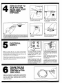
4
HERE IS WHAT TO
DO IF YOU ARE
INSTALLING YOU R
SINK'S FIRST
DISPOSER,
EXTENSION
TUBE
Use a pipe wrench to loosen the
nut at the top of the drain trap.
Next, remove the nut at the top of
the sink strainer
and remove
the
extension
tube.
E.
Now, remove the large nut at the base of the sink strainer by placing the
tip of your screwdriver on the edge of the nut. (There are usually ridges
to hold your screwdriver,) Then strike the head of the screwdriver with
a hammer in a counterclockwise direction.
Loosen the nut until you can spin it
off by hand.
@
SUPPLY.
ELECTRICAL
Before you begin this job, you should be thoroughly
familiar with electrical power and proper procedures.
Local
electrical
codes
in a professional
must be followed.
is equipped
ductor
cable in accordance
copper
If you are not sure, call
who is knowledgeable.
This appliance
make your connections
with copper
wires.
Now, push the strainer up through
the sink hole and remove it.
Use 3 con-
First, remove the fuse or turn off the
circuit breaker on the circuit you plan
to use for your disposer.
Use a
separate 15 or 20 amp., 115 volt circuit for the disposer.
If you are replacing
skip to Step 6.
an old disposer,
with your local code to
to the unit.
SEALANT FROM
THE RIM
OFOLD
THE
CLEAN
THE
SINK HOLE.
Use your screwdriver
or a putty knife to scrape away all
traces of the old putty or caulking from the edge of the sink
drain hole. Make sure you get this as clean as possible so
that you'll have a good, water-tight
seal for your new
disposer sink sleeve.
Except for batch feed models, this
disposer requires that a wall switch
with a marked off position and wired to
disconnect
all ungrounded
supply
conductors be installed within sight of
the disposer sink opening.
It will be necessary to install a 20 amp.
walt switch above the countertop and a
junction
box under the sink as
illustrated.
Position the switch in any convenient
location, and connect to junction box.
All wiring must comply with local
electrica! codes.
14 gauge size wire is the smallest permissible for use with a 15 amp. circuit,
and 12 gauge size wire is the smallest
permissible
for use with a 20 amp.
circuit.
w
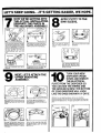
LET'S KEEP GOING...IT'S
7
Mounting
Assembly
GETTING
NOW WE'RE GETTING INTO
THE ACTUAL INSTALLATION.
SEPARATE THE PARTS IN
THE MOUNTING ASSEMBLY.
_,_
8
EASIER, WE HOPE.
APPLY PUTTY TO THE
SINK SLEEVE.
Lower
_Mounting "
Ring
/
B.
A=,,
First, remove the mounting assembly
from the dower mounting ring, Holding
the mounting assembly with one hand,
insert your wrenchette or screwdriver
inlo one of the lugs of the tower mounting ring end turn it to the Jeff
(counterclockwise)
with your other
hand
Then loosen the screws on the mounting assembly until they are just level
with the surface of the mounting ring.
Make a fat snake of "plumber's"
patty by rolling it between
your
hands.
Apply this roll under the rim of the
sink steeve
ID
Groove
'_
SineSleeve
•
Now, use a screwdriver
snap ring
to pry off the
_.%°"°g
The assembly will now come apart. Set
it aside and move to the next step.
UPPER MOUNTING
NEXT,
LET'S ATTACH THE
ASSEMBLY.
B,
First, working from under the sink, slip the
fiber gasket
and next the metal
back-up
ring
(flat side up} up and over the sink
sleeve,
Then, place the sink sleeve into the
sink drain hole and push down
gently but firmly to make sure it sits
evenly in the putty.
Hold the fiber gasket and metal back- UP
ring in place with one hand and place
the mounting ring with its three screws onto
the sink sleeve.
DISPOSER UPSIDE
DOWN YOUR
AND REMOVE
0
TURN
NEW
THE ELECTRICAL
PLATE FROM THE DISPOSER SO
YOU CAN SEE THE WIRING AND
THE GROUND SCREW. THE BOTTOM
OF YOUR DISPOSER WILL LOOK
LIKE THE ONES SHOWN IN 'A' OR 'B'.
(Start here if you are replacing a disposer with the same mouni_ng.)
Remove the electrical plate lrom the bottom of the disposer and pull out the
black and white electrical wires The green ground screw is also under this
plate.
BLrrTON
rC_
Now, push the fiber gasket, metal back-_.
ring and the mounting ring further up on the
sink sleeve. Slide the snapring onto the sink
sleeve until it POps into place in the groove
:_nthe sleeve.
T_hten the three mounting screws with
your screwdriver until the whole mounting
assembly te seated evenly and t_ghtly
againstthe sink.
I'r!l
11
A
WE'RE READY TO MAKE THE ELECTRICAL CONNECTIONS.
NOTE: Ifusing armored cable, we recommend installing an anti-short or insulation bushing in the end of the cable,
Do not fold or remove the
brown
electrical insulation
paper from inside the wiring
compartment,
Install the cable connector. Then
loosen the connector screw(s).
(Some disposers have a connector built in, on ethers you will
have to instalt one which must
meet local electrical codes).
Work the cable from the on-off
switch through the connector so
that the leads are in the electrical
widng area in the disposer base.
_onnector
Wire nut
Screws
!
Now, tighten the connector
clamp screw{s)
to hold the
cable in place.
Connect the two power wires to
the cable wires, making sure
you connect white to white
and black to black, Secure the
wires with wire nuts by twisting
them to the right (clockwise).
Finally, place the connected
wires back in the compartment.
If you are using the built-in
cable clamp loosen the two
screws until cable will freely
enter under the clamp.
Work the cable from the on-off
switch through the connector
so thatthe leads are in the electrical wiring area in the disposer
base.
W=re nut
Now, tighten the connector
clamp screw{s) to hold the
cable in place.
F.
Plug
Connect the two power wires to
the cable wires, making sure
you connect white to white
and black to black. Secure the
wires with wire nuts by twisting
them to the right (clockwise).
If
you are
"Greenfield"
Cable
then using
the plug
must be
removed.
Wire
nul
Install the cable connector. Then
loosen the connector screwls I.
Work the cable from the on-off
switch through the connector
so thatthe leads are in the electrical wiring area in the disposer
base.
Finally, place the connected
wires back in the compartment.
Replace electrical plate.
Now, tighten the connector
clamp screw(s) to hold the
cable in place.
Connect the two power wires to
the cable wires, making sure
you connect white to white
and black to black, Secure the
wires with wire nuts by twisting
them to the right (clockwise).
"
SURE THE DISPOSER IS GROUNDED.
NEXT, MAKE
Green
Ground
Screw
If the cable leading to the
disposer has three wires, attach the green ground wire to
the green ground screw.
!:d.,"T",'-'-i.
If the cable leading to the
disposer does not have a
ground wire, use a copper
wire that is no smaller than the
other wire in your cable. At*
tach one end of the wire to the
green ground screw on the
disposer,
P'-"
jj/
B.
Attach the other end of this
ground wire to the metal cold
water pipe. NOTE: Be sure
that this cold water pipe is
continuous metal pipe from
under the sink to the ground
(earth). Use only an Underwriters
Laboratories,
Inc.
listed
(approved)
ground
clamp to attach the ground
wire to the pipe. If non-metal
pipe is used in your home
water connections or if plastic
pipe is used in your water
supply pipe, you will need a
qualified elacb'ician to install a
proper ground. Now, replace
the electrical plate.
i
I
C,
COLD
,
GroundClamp
Ground
j
Ground
If you have a water meter in
your home, check the meter
Io see if there is a wire that
comes across iL If there is no
wire, your cold water pipe is
NOT GROUNDED.
To properly ground it, add a
copper wire as shown at right.
Use only Underwriters Laboratories, Inc. listed (approved} ground clamps to attach
wire to pipe.
-- ff6 Copper
Wire
Wire
for 200 Amp. Or Less
Electrical Services
Water Line
WARNING: IF NOT PROPERLY GROUNDED, a hazard of electrical shock
may exist. DO NOT reconnect electrical power at main service panel until
proper ground is installed. For your safety, DO NOT ground to a gas supply pipe.
//Sore,,,
/
_
Water Meter
D.
/
Ground Clamp
....,,,,,,
PREPARING THE
DISHWASHER DRAIN
CONNECTION.
If
,
you
do
dishwasher
tostep14.
NOT
plan
to
connect
drain to the disposer,
THE DISPOSER
ITS MOUNTING
ASSEMBLY.
a
Lay the disposer on its side and put the tip of your
screwdriver into the dishwasher drain hole opening
atanangle.
Tap the end of the screwdriver with a hammer until
the molded plug pops out. Make sure you take
the Ioose plug out of your disposer.
Lift the disposer and place it so the disposer's three
mounting lugs are lined up under the three sink
mounting assembly screws.
Then,
while holding the disposer
in place, lurn
mounting ring with the lugs to the right until all three
ears are engaged
on the mounting
assembly.
The
disposer
will new hangs by itself. You will lock this
ring later, after the plumbing
connections are made.
go on
TO
_r_-
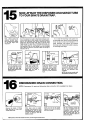
15
NOW, ATTACH THE DISPOSER DISCHARGE TUBE
TO YOUR SINK'S DRAIN TRAP.
\
First, check inside the
disposer grinding chainber to remove any objects
or dirt that might have
dropped in,
Turn the disposer around to attach the discharge tube.
Some models use a rubber washer that must be assembled to the discharge tube before putting the metal
flange over the discharge tube, see 'D'. Secure metal
flange using the edge tab on the flange and screw. On
other models, put the rubber washer in the discharge
tube opening. Slip the metal flange over the discharge
tube. Using the screw(s) provided, attach the flange to
disposer, see 'E'.
Discharge
Extension
I
F.j
I
TUBE TOO LONG? Simply cut off as much as you
need to with a hack saw.
Make sure you have a
clean, straight cuL
Turn the disposer so that
the discharge tube lines
up with your drain trap.
Slip the drain trap over the
discharge tube.
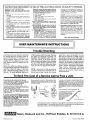
16
In D. install the discharge tube gasket onto
the discharge tube. Gasket must be installed as
shown to assure a leak-proof installation. In E
install discharge tube gasket into disposer
discharge outlet. Gasket will be held in place by
the discharge tube flange.
DISHWASHER
TUBE TOO SHORT? If the
discharge
tube doesn't
reach your drain trap outlet,
measure
the difference.
Then buy a drain extension
tube.
NOTE: Be sure you comply with
all applicable plumbing codes.
DRAIN CONNECTION.
NOTE: (If necessary) An approved dishwasher drain connection
plPler
I
If it fits. simply tighten the slip
nut on the trap with a pipe
wrench to make your connection to the discharge tube
complete,
kit is available from Sears.
Clamp
Dishwasher__
DrainHose
Remove the clamp or fittings
from the end of your dishwasher drain hose.
Slide large end of rubber
coupler, from dishwasher drain
connection kit, over the inlet
tube of the disposer. Fasten the
coupler to disposer with the
clamp provided.
nsert one end of the plastic
tube intothe coupler and fasten
with _ inch clamp.
NOTE: Check the three clamps to be sure you have tightened all of them.
Slip the remaining clamp (the
one you pruchased) over the
dishwasher
drain hose and
back two or three inches. No_
slip the drain hose over the
plastic tube, slidethe clamp into
place and tighten.
7
DISPOSER IN
PLACE.
NOW, LOCKTHE
8
LEAKS
CHECK FOR
Place the end of your "wrenchette" or a screwdriver into the
left side of one of the mounting
ring lugs at the top of the
dispose_ Then, turn the "wrenchette" or screwdriver to the
right until the disposer locks in
place.
Run water
through
the
disposer. Then, place the
stopper in the sink sleeve in
the seal position. Fill the
sink with water.
19
Finally, remove the stopper
and let the water drain.
Check for leaks at al! plumbing connections and at the
lop of the disposer and correct, if you need to.
CHECK DISPOSER OPERATION
Turn electrical power back on at your service panel (fuse box or circuit breaker box). Turn on the
cold water and leave running, turn on the disposer. You may wish to check again for leaks
before turning the disposer off.
CARE AND USE OPERATING
qTINUOUS FEED MODELS
move the stopper |rom the disposer throat.
I on the cold water and start the disposer by
ing on the control wall switch,
Feed food
te into the disposer and position the stopper to
mize the possible ejection of material while
:_ing(see illustration.)
"CH FEED MODELS
love the special stopper from the disposer
_t. Turn on the cold water and then place the
waste into the disposer grind chamber. DO
t" PACK THE CHAMBER WITH WASTE.
replace the stopper in the disposer throat,
on the disposer by lifting the stopper slightly
turning it to the right or left until the disposer
s. The switch to the batch feed disposer is
into the unit and is actuated by the stopper.
"ER USAGE - ALL MODELS
recommended water flow for efficient grinding
grind food waste only with a strong flow of
water,
;rind hard material such as bones, fruit pits,
A scouring action is created by the particles
e of the grind chamber.
::lispose of coffee grounds in your disposer
rdless of whether or not you are on
opolitan sewer or septic tank. Coffee
nds will not harm the action of the septic
tispose of small amounts of fats and greases
)ur disposer. Be sure to have the disposer
ating and use a strong flow of cold water. If
have a large amount of fat and grease, we
lest you place it in a conta ner allow it to
i_, then dspose of it in the trash.
flush disposer for cleaning. Allow disposer
II
INSTRUCTIONS
is 1 1/2 gallons per minute (medium to lull faucet
flow.) Remember to turn the water on first, and
then the disposer to avoid a possible drain blockage. After grinding is complete, the disposer and
water may be turned off.
REMEMBER THESE OPERATING INSTRUCTIONS WHEN USING YOUR DISPOSER.
- DO NOT INSERT HAND INTO THE DISPOSER.
- IF THE DISPOSER JAMS, OR THE MOTOR
PROTECTOR
TRIPS, DISCONNECT
THE
POWER TO THE DISPOSER BEFORE FREEDepending upon your particular installation, it may
ING THE JAM, OR RESETTING THE MOTOR
be necessary to allow a water flush after grinding
to completely clear the horizontal drain line. The _1, PROTECTOR'
WARNING
water flow time after grinding will depend on the
- USE THE STOPPERS IN THE DRAIN/GRIND
quantity of food waste that was ground, and the
length of the horizontal drain line. Ground food
POSITION WHILE GRINDING TO MINIMIZE
POSSIBLE EJECTION OF MATERIAL.
waste and water flow at an approximate rate of 2
seconds per foot in a properly pitched horizontal
drain pipe.
DO'S AND DON"IS
and cold water to run after grinding or after draining sink of dish water. Some detergents are
caustic; flushing will pass such material into the
drain line without disposer damage.
DON'T use hot water when grinding food waste,
However, hot water can be drained into the
disposer between gdnding periods
DON'T turn off motor or water until grinding is
completed and only a motor and water sound is
heard.
DON'T become alarmed if a brown discoloration
appears on the face of the grinding disc. This is
normal. It is a surface discoloration only and will
not affect the life or performance of the disposer,
DON'T grind extremely fibrous material like corn
husks, artichokes, etc. to avoid possible drain
blockaae.
Stoppers are In drain/grind
position.
If you should encounter an objectionable odor
coming from your disposer, it may be the water
itself, which in some areas develops a slightodor
at times. Or it may be coming from bits of food
waste left inside the disposer, because the unit
was turned off before the grind cycle was compleled or not enough water was used. Try this
remedy, after all remaining food waste is disposed of inside the unit:
Heat a large pan of water (approximately 3 to 4
quarts). To this add one-half cup of baking soda.
Mix in thoroughly so it is completely dissolved.
When water reaches approximate boiling point,
tum disposer on and pour heated mixture into
sink. This hot, swirling, treated water will then
flush the inside of the disposer housing.
INSTRUCTIONS
PERTAINING
TO A RISK OF FIRE, ELECTRICAL
IMPORTANT SAFETY INSTRUCTIONS
WARNING:
When using electric appliances, basic
precautions should always be followed, including the
following:
1.Read
all the instructions
before using the
appliance.
2.To reduce the risk of injury, close supervision is
necessary
when an appliance
is used near
children,
3. Do not put fingers
or hands into a garbage
disposer,
4, Turn the power switch to the off position before
attempting to clear a jam or remove an object
from the disposer.
&When
attempting to loosen a jam in a garbage
disposer,
use a self-service
wrenchette
as
described below.
&When
attempting
to remove
objects
from
a garbage disposer
use long-handled
tongs or
pliers.
7.To reduce the risk of injury by materials that may
be expelled by a food waste disposer place the
stopper in the drain grind position.
when feedino the food waste so that foreion
[[
SHOCK,
obiacts do not enter the arind chamber that may
be exoe;led. Reolace the anti-solash baffle when
it becomes worn to reduce solashine and election.
Do not put the following into a disposer:
a. Clam and oyster shelts.
b. Drain cleaner.
c. Glass, china, plastic, plastic wrap or bags.
d. Large whole bones.
e. Metal, such as bottle caps, tin cans, aluminum
foil or eating utensils.
8.When not operating a disposer, leave the drain
cover in place to reduce the risk of objects falling
into the disposer.
9. Before pressing red reset button, (see Fig. 4),
be sure the wall switch is in the off position
and on batch feed models remove the stopper
from the run position.
10. a. GROUNDING
INSTRUCTIONS
FOR CORD
CONNECTED
UNITS. This appliance must be
grounded,
tn the event of a malfunction or
breakdown, grounding provides a path of least
resistance for electdc current to reduce the risk
OR INJURY TO PERSONS.
conductor and a grounding plug, the plug must
be plugged into an appropriate
outlet that is
properly installed and grounded in accordance
with all local codes and ordinances.
DANGER - Improper connection o! the equipment-grounding conductor can result in a risk of
electric shock.
Check with a qualified electrician or serviceman
if you are in doubt as to
whether the appliance
is properly grounded.
Do not modify the plug provided with the appliance -- if it will not fit the outlet, have a proper
outlet installed by a qualified electrician.
b.GROUNDING
INSTRUCTIONS
FOR PERMANENTLY
CONNECTED
UNITS:
This appliance must be connected to a grounded, metal,
permanent
wiring system; or an equipmentgrounding
conductor
must be run with the
circuit conductors
and connected
to the
equipment-grounding
terminal or lead on the
appliance.
of electric shock. If this appliance is equipped
with a cord having an equipment-grounding
USER MAINTENANCE
SAVE THESE INSTRUCTIONS
INSTRUCTIONS
Trouble Shooting
Loud noises while your disposer is operating
are usually caused by dropping metal objects into the disposer. To correct this, turn
off the disposer switch and water. After
grinding disc has stopped turning, investigate. Remove object by reaching into unit
with tongs.
Motor stops while your disposer is operating. This can be caused by overloading the
unit. First, check the cause of the overload - often some foreign material is in the
disposer. To avoid personal injury turn
off the disposer switch and water. Remove
the object as previously explained. TO
RESTART THE MOTOR: wait 3 to 5 minutes, then push in on the small red reset
button located on the bottom of your disposer
(Fig. 1). If motor remains inoperative, check
your Service Panel and replace any blown
fuses, or look for a tripped circuit breaker.
NOTE: If water does not drain as readily as
you think it should, and food waste tends to
float or take too long to grind, don't reduce
water flow to solve this problem.
It is very
likely that the drain line is partially clogged
and should be cleaned with a drain auger. A
blocked drain may also cause food waste to
drain into the dishwasher.
Like any precision
machine, your disposer was built to perform
a particular job. If unusual demands are placed on it, service interruptions
are possible.
These
service
interruptions,
mentioned
below,, are usually not serious and in most
cases, can be remedied without
calling a
service technician.
To Save The Cost of a Service Call to Free a Jam.
To save the cost of a service call to free a jam.
The accidental entry of foreign material will cause any
disposer to jam occasionally. To tree ammed material,
follow these steps to avoid persona! injury:
1oTurn off disposer and shut off cold water.
2, Insert one end of yo_r Self-Service Wrenchette provided with your disposer, into the center hole of the bottom of the disposer as shown. (Fig. 2).
3. Work the Wrenchette back and forth until it moves
freely for at least one compiete revolution. Remove
foreign object with tongs. Remove Wrenchette before
restarting disposer.
4. Wail 3 to 5 minutes to allow disposer motor to cool an d
then push red reset button, Fig. 1 ).Before pressing red
reset button be sure the wa I switch is In the off
position and on batch feed models remove the
stopper from the run position,
Your Sell-Service Wrenc helle willfree virtually eve ryjam
that may occur due to foreign ebects entering the
disposer. Very rarely, however, a piece of meLal bobby
pin, thumb tack, paper clip, silverware, etc.) causes a
jammed condition too tight for your Self-Service
Wrenchette to handle, To free this type of jam, e pry bar or
tool must be used.
Be sure wail switch is turned off. Remove as much food
waste from the disposer as is possible with tongs. Use a
flashlight to determine the direction the unit was running
at the time of thejam.
A pry bar or tool should be inserted
through the sink
opening
into the disposer.
The end then must be placed
alongsid e the grinding
protrusion
near the outside
edge
of ths grinding
disc. Be sure to place the pry tcol on the
proper side of the protrusion
so when pressure is applied
the grinding
disc wilt move in the proper
direction
to unjam the disposer,
{see Fig, 3). Do not drop or hammer on
pry bar.
LOSE
Fig. 3
YOUR
SELF
SERVICE
WRENCHETTE?
It you lose your Self-Service Wrenchette, a replacement may be or.,/,//
dered, free of charge, through
the Customer Service Depart_"iJ#"
ment of your locaJ Sears
z_._
store or service cent er.
X_'_"
"_
part number of
_/
"_
the wrench Is
XY!
"
2035.03.
/_./7
_/,_Inch Hex Wrench
When warranty service is neededl simply call the Dearest Sears Service Center in
the United States. "We service what we sell" is our assurance to you that you can
depend on Sears for service and Sears service is nationwide.
Sears, Roebuck and Co., Hoffman Estates, IL 60179 U.S.A.
Printed in U.S.A.
Part No. 71865 (4/98)