1
DL-V3
User Manual
OM-20000119 Rev 3
DL-V3 User Manual
Publication Number:
Revision Level:
Revision Date:
OM-20000119
3
2009/07/22
Proprietary Notice
Information in this document is subject to change without notice and does not represent a commitment
on the part of NovAtel Inc. The software described in this document is furnished under a licence
agreement or non-disclosure agreement. The software may be used or copied only in accordance with
the terms of the agreement. It is against the law to copy the software on any medium except as
specifically allowed in the license or non-disclosure agreement.
No part of this manual may be reproduced or transmitted in any form or by any means, electronic or
mechanical, including photocopying and recording, for any purpose without the express written
permission of a duly authorized representative of NovAtel Inc.
The information contained within this manual is believed to be true and correct at the time of
publication.
NovAtel, Narrow Correlator tracking technology, ProPak, and RT-2 are registered trademarks of
NovAtel Inc.
RT-20, PAC, AdVance RTK, OEMV and DL-V3 are trademarks of NovAtel Inc.
The Bluetooth® word mark and logos are registered trademarks owned by Bluetooth SIG, Inc. and
any use of such marks by NovAtel Inc. is under license. All other brand names are trademarks of their
respective holders.
Manufactured and protected under U.S. Patent:
PAC Correlator
#6,243,409 B1
#5,414,729
Narrow Correlator
#5,101,416
#5,390,207
#5,495,499
#5,809,064
GLONASS
#6,608,998 B1
GALILEO
#6,184,822 B1
Dual Frequency GPS
#5,736,961
Position for Velocity Kalman Filter
#6,664,923 B1
Anti-Jamming Technology
#5,734,674
RTK Positioning
#6,728,637 B2
#6,664,923 B1
© Copyright 2007-2009 NovAtel Inc. All rights reserved. Unpublished rights
reserved under International copyright laws. Printed in Canada on recycled paper.
Recyclable.
2
DL-V3 User Manual Rev 3
Table of Contents
Software License
Terms and Conditions
Warranty
Notices
Customer Service
Foreword
11
13
15
16
20
21
Congratulations!......................................................................................................... 21
Scope......................................................................................................................... 21
Prerequisites .............................................................................................................. 21
Conventions ............................................................................................................... 22
1 Introduction
23
1.1 Models and Features ............................................................................................ 23
1.2 Operating Modes .................................................................................................. 24
2 Installation and Setup
25
2.1 Additional Equipment Required ............................................................................ 25
2.1.1 DL-V3 Setup ................................................................................................ 25
2.1.2 Installing the PC Utilities.............................................................................. 30
2.1.3 Selecting a GNSS Antenna ......................................................................... 30
2.1.4 Choosing a Coaxial Cable ........................................................................... 31
2.1.5 Power Supply Requirements ....................................................................... 31
2.1.6 Mounting Bracket......................................................................................... 32
2.1.7 Mounting the GNSS Antenna ...................................................................... 32
2.1.8 Connecting the Antenna to the Receiver..................................................... 32
2.1.9 Applying Power to the Receiver .................................................................. 32
2.1.10 Connecting Data Communications Equipment.......................................... 33
2.2 Additional Features and Information ..................................................................... 34
2.2.1 Strobes ........................................................................................................ 34
2.2.2 Universal Serial Bus (USB) ......................................................................... 34
2.2.3 Status Indicators.......................................................................................... 35
2.2.4 External Oscillator ....................................................................................... 38
2.2.5 Antenna LNA Power .................................................................................... 39
2.2.6 DL-V3 Removable Compact Flash Memory Card ....................................... 39
3 Operation
44
3.1 Communications with the Receiver....................................................................... 44
3.1.1 Serial Port Default Settings ......................................................................... 44
3.1.2 Communicating Using a Remote Terminal.................................................. 45
3.1.3 Communicating Using a Personal Computer .............................................. 45
3.2 Getting Started...................................................................................................... 45
3.2.1 Starting the Receiver ................................................................................... 45
3.2.2 Communicating with the Receiver Using CDU ............................................ 45
3.3 Transmitting and Receiving Corrections ............................................................... 47
DL-V3 User Manual Rev 3
3
Table of Contents
3.3.1 Base Station Configuration ......................................................................... 49
3.3.2 Rover Station Configuration........................................................................ 50
3.3.3 Configuration Notes .................................................................................... 50
3.4 Using the DL-V3 ................................................................................................... 51
3.4.1 Log Data from a Site to a File ..................................................................... 51
3.5 Enabling SBAS Positioning .................................................................................. 53
3.6 Enabling L-band (OEMV-1, OEMV-3, DL-V3 & ProPak-V3) ................................ 53
3.7 Pass-Through Logging ......................................................................................... 54
3.8 T Sync Option....................................................................................................... 55
4 DL Explorer
56
4.1 Basic Operations .................................................................................................. 56
4.1.1 Starting DL Explorer.................................................................................... 56
4.1.2 Exiting DL Explorer ..................................................................................... 57
4.2 Receiver Operations............................................................................................. 57
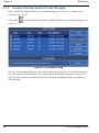
4.2.1 Receiver Groups ......................................................................................... 57
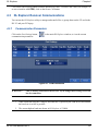
4.3 DL Explorer Receiver Communications................................................................ 65
4.3.1 Communication Parameters ....................................................................... 65
4.3.2 Upload Group from the PC/Laptop to the Receiver .................................... 66
4.3.3 Transfer a File from the DL-V3 to the PC/Laptop ....................................... 68
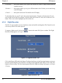
4.3.4 Flight Recorder ........................................................................................... 70
4.3.5 CF Card Status ........................................................................................... 71
A Technical Specifications
72
OEMV Family Receiver Performance ........................................................................ 72
DL-V3 Specifications ................................................................................................. 73
B Commands
81
Syntax Conventions .................................................................................................. 84
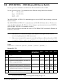
APPCONTROL COM3 Bluetooth/Ethernet Switch ................................................. 85
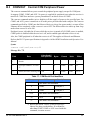
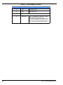
COMVOUT Control COM Peripheral Power ........................................................... 87
CURRENTFILE Specify File for FILEHDR/FILETRANSER Logs ........................... 89
CURRENTGROUP Specify File for GROUPDEF Log ............................................ 90
DEL Delete Files from CF Card .............................................................................. 91
DISK Format the CF Card ...................................................................................... 92
EXTCONTROL Disable Automatic POWERUP Group ........................................... 93
FRESET Clear Selected Data from NVM and Reset .............................................. 94
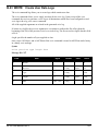
GROUP Create and Manipulate Groups ................................................................. 95
GROUPANTHEIGHT Edit Group Antenna Height .................................................. 97
GROUPANTSN Edit Group Antenna Serial Number .............................................. 98
GROUPANTTYPE Edit Group Antenna Type ......................................................... 99
GROUPCOM Associate Port Configurations with a Group ................................... 100
GROUPCOMVOUT Control COM Power for a Group .......................................... 103
GROUPDGPSTXID Edit Group DGPS ID Configuration ...................................... 105
GROUPECUTOFF Edit Group Elevation Cut-Off Angle ....................................... 107
GROUPFIXPOS Configure Group to Fix Receiver Position ................................. 108
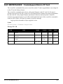
GROUPINTERFACEMODE Edit Group Interface Mode ...................................... 109
GROUPLOG Edit Group Logging Specifications .................................................. 111
GROUPMODE Configure Group Survey Type ..................................................... 113
4
DL-V3 User Manual Rev 3
Table of Contents
GROUPPOSAVE Configure Group Position Averaging ........................................ 114
GROUPSATLIMIT Limit Number of Satellites for Group ....................................... 115
GROUPSITENAME Edit Group Site Name ........................................................... 116
GROUPSITENUMBER Edit Group Site Number .................................................. 117
GROUPUSE Execute a Set of Commands ........................................................... 118
LOG Request Logs from the Receiver .................................................................. 120
LOGFILE Open or Close File on CF Card ............................................................. 125
METHUMID Specify Air Humidity .......................................................................... 127
METPRESS Specify Air Pressure ......................................................................... 128
METTEMP Specify Air Temperature ..................................................................... 129
PROJECT Add or Clear a Project ......................................................................... 130
RENAME Rename a File on the CF Card ............................................................. 131
RESET Perform a Hardware Reset ....................................................................... 132
SATLIMIT Set Minimum Satellites in Position Solution ......................................... 133
SITE Control Site Occupations .............................................................................. 135
SITEUPDATENUMBER Set Occupied Site Number ............................................. 137
SITEUPDATENAME Set Occupied Site Name ..................................................... 138
SITEUPDATEANTHEIGHT Set Occupied Site Height .......................................... 139
SITEUPDATEANTTYPE Set Occupied Site Antenna ........................................... 140
SITEUPDATEATTRIBUTE Set Occupied Site Attributes ...................................... 141
SOFTPOWER Simulate a Power-Button Off ......................................................... 142
WRITE Create User Data Logs ............................................................................. 143
WRITEFILE Create/Append Files on CF Card ...................................................... 144
WRITEFILEHEX Create/Append Data to CF Card ............................................... 145
WRITEHEX Create User Data Logs ...................................................................... 146
C Logs
147
PDC Files ................................................................................................................. 149
CURRENTSET CURRENTFILE/CURRENTGROUP Configuration ..................... 153
DIRENT CF Card File List ..................................................................................... 154
EXTLEVELS Extended Hardware Levels .............................................................. 156
FILECHANNEL Log File Channel Configuration ................................................... 157
FILEHDR Logfile Header ....................................................................................... 158
FILETRANSFER Log File Contents ...................................................................... 160
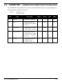
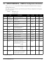
GROUPCOMCONFIG COM Port Configuration Information ................................ 161
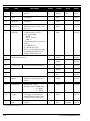
GROUPDEF Log Group Configuration .................................................................. 163
METDEF Meteorological Parameters .................................................................... 168
PROJECTDEF Project Definition .......................................................................... 169
PWRSTATUS Power and Status Settings Summary ............................................ 170
RXSTATUS DL-V3 Status ..................................................................................... 172
RXSTATUSEVENT DL-V3 Status Event Notification ............................................ 175
SITEDEF Site Configuration .................................................................................. 176
VERSION HW & SW Versions and Serial Numbers ............................................. 177
WRITE User-Generated Information ..................................................................... 177
WRITEHEX User-Generated Information .............................................................. 177
D Ethernet Configuration
178
Physical Set-Up ....................................................................................................... 178
DL-V3 User Manual Rev 3
5
Table of Contents
Configuration Overview ........................................................................................... 179
Alternative Serial Configuration ............................................................................... 188
E Bluetooth Configuration
195
Enable Bluetooth on the DL-V3 Receiver ................................................................ 195
Set Up a PC/Laptop with a Bluetooth Adaptor ........................................................ 195
Locate a Bluetooth-Enabled DL-V3 in Range ......................................................... 196
Communicate with the DL-V3 Using Bluetooth ....................................................... 197
Stop Communicating with the DL-V3 Using Bluetooth ............................................ 198
F Replacement Parts
200
DL-V3 ...................................................................................................................... 200
Accessories ............................................................................................................. 200
Manufacturer’s Part Number ................................................................................... 200
6
DL-V3 User Manual Rev 3
Figures
1
2
3
4
5
6
7
8
9
10
11
12
13
14
15
16
17
18
19
20
21
22
23
24
25
26
27
28
29
30
31
32
33
34
35
36
37
38
39
40
41
42
43
44
45
46
47
Primary and Secondary Lightning Protection ................................................................... 18
DL-V3 Receiver ................................................................................................................ 23
Antenna Port .................................................................................................................... 26
COM1 Port (left) and USB Port (right) .............................................................................. 26
Ethernet Port .................................................................................................................... 27
Bluetooth Interface at the Top of the DL-V3 ..................................................................... 27
Power Port ....................................................................................................................... 27
DB-9 Setup ....................................................................................................................... 28
USB Setup ....................................................................................................................... 28
Bluetooth Setup ................................................................................................................ 29
Ethernet Setup ................................................................................................................. 29
OEMV CD ........................................................................................................................ 30
Power Button .................................................................................................................... 33
External Oscillator Port .................................................................................................... 38
64 MB Flash Card ............................................................................................................ 39
Compact Flash Card Door (shown with its latch in the open position) ............................. 40
Basic Differential Setup .................................................................................................... 48
DL Explorer Main Window ................................................................................................ 56
DL Groups Dialog ............................................................................................................. 57
Add Log ............................................................................................................................ 58
Position Tab ..................................................................................................................... 61
Site Tab ............................................................................................................................ 62
Interfaces Tab .................................................................................................................. 63
Ports Tab .......................................................................................................................... 64
COM Parameters ............................................................................................................. 65
Group Management ......................................................................................................... 66
Starting Groups ................................................................................................................ 67
Log Transfer Dialog .......................................................................................................... 68
File Details ....................................................................................................................... 69
Download Progress Bar ................................................................................................... 69
Flight Recorder: OFF ....................................................................................................... 70
Flight Recorder: ON ......................................................................................................... 70
CF Card Status ................................................................................................................ 71
DL-V3 Power Cable ......................................................................................................... 77
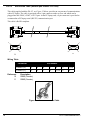
DL-V3 Null-Modem Cable ................................................................................................ 78
DL-V3 Straight Through Serial Cable ............................................................................... 79
DL-V3 I/O Strobe Port Cable ............................................................................................ 80
DL-V3 Voltage Parameter Logs ..................................................................................... 170
Sheilded CAT5 Ethernet Cable Connection ................................................................... 179
Lantronix COM Redirector Manager .............................................................................. 186
Lantronix Port Redirector: Com Setup Screen ............................................................... 187
Command Mode Example .............................................................................................. 191
Bluetooth Adapter for PC/Laptop ................................................................................... 195
Bluetooth Standby: White ............................................................................................... 195
Bluetooth Error: Red ...................................................................................................... 196
My Bluetooth Places Window ......................................................................................... 196
Bluetooth PIN Code Request ......................................................................................... 197
DL-V3 User Manual Rev 3
7
Figures
48
49
50
8
COM3: PC/Laptop COM Port Assignment ..................................................................... 197
Bluetooth Connected: Green ......................................................................................... 198
COM3: Disconnect? ....................................................................................................... 199
DL-V3 User Manual Rev 3
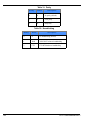
Tables
1
2
3
4
5
6
7
8
9
10
11
12
13
14
15
16
17
18
19
20
21
22
23
24
25
26
27
28
29
30
31
32
33
34
35
36
37
38
39
40
41
42
43
44
45
46
47
DL-V3 Controller Models............................................................................................ 23
GPS Positioning Modes of Operation ........................................................................ 24
NovAtel GNSS Antenna Models ................................................................................ 31
Enclosure Power Requirements................................................................................. 32
Default Serial Port Configurations.............................................................................. 33
Satellite Tracking LEDs.............................................................................................. 36
Flash Card Memory LEDs.......................................................................................... 36
Positioning Mode LEDs.............................................................................................. 37
Occupation Time LEDs .............................................................................................. 38
Log Triggers ............................................................................................................... 59
DL-V3 Serial Port Pin-Out Descriptions ..................................................................... 76
DL-V3 I/O Port Pin-Out Descriptions.......................................................................... 76
DL-V3 Commands in Alphabetical Order ................................................................... 81
DL-V3 Commands in Order of their Message IDs...................................................... 82
Application Functions ................................................................................................. 86
Application Parameters .............................................................................................. 86
COM Serial Port Identifiers ........................................................................................ 87
COM Voltage Out Action............................................................................................ 88
Dump Mode................................................................................................................ 89
CURRENTFILE Default Configuration ....................................................................... 89
CURRENTGROUP Default Configuration.................................................................. 90
Delete Target ............................................................................................................. 91
CF Card Operation..................................................................................................... 92
FRESET Target.......................................................................................................... 94
Action ......................................................................................................................... 96
GROUP Default Configuration ................................................................................... 96
GROUPANTHEIGHT Default Configuration .............................................................. 97
GROUPANTSN Default Configuration ....................................................................... 98
GROUPANTTYPE Default Configuration................................................................... 99
Parameter Update.................................................................................................... 101
Parity ........................................................................................................................ 102
Handshaking ............................................................................................................ 102
GROUPDGPSTXID Default Configuration ............................................................... 106
Parameter Update.................................................................................................... 107
GROUPECUTOFF Default Configuration ................................................................ 107
GROUPFIXPOS Default Configuration .................................................................... 108
GROUPINTERFACEMODE Default Configuration .................................................. 110
GROUPLOG Default Configuration.......................................................................... 112
Group Mode ............................................................................................................. 113
GROUPMODE Default Configuration ...................................................................... 113
GROUPSAVE Default Configuration........................................................................ 114
GROUPSATLIMIT Default Configuration ................................................................. 115
GROUPSITENAME Default Configuration ............................................................... 116
GROUPSITENUMBER Default Configuration.......................................................... 117
Group Action ............................................................................................................ 119
Detailed Serial Port Identifiers.................................................................................. 123
Log File Action ......................................................................................................... 126
DL-V3 User Manual Rev 3
9
Tables
48
49
50
51
52
53
54
55
56
57
58
59
60
61
62
63
64
65
66
67
68
69
70
71
72
73
74
75
76
77
78
79
80
81
82
83
10
LOGFILE Default Configuration ............................................................................... 126
METHUMID Default Configuration ........................................................................... 127
METPRESS Default Configuration .......................................................................... 128
METTEMP Default Configuration............................................................................. 129
Project Action........................................................................................................... 130
PROJECT Default Configuration ............................................................................. 130
File Port Channel ..................................................................................................... 134
SATLIMIT Default Configuration .............................................................................. 134
Site Mode................................................................................................................. 136
SITE Default Configuration ...................................................................................... 136
SITEUPDATENUMBER Default Configuration ........................................................ 137
SITEUPDATENAME Default Configuration ............................................................. 138
SITEUPDATEANTHEIGHT Default Configuration ................................................... 139
SITEUPDATEANTTYPE Default Configuration ....................................................... 140
SITEUPDATEATTRIBUTE Default Configuration.................................................... 141
Softpower................................................................................................................. 142
DL-V3 Logs in Alphabetical Order ........................................................................... 147
DL-V3 Logs in Order of their Message IDs .............................................................. 148
PDC Log Header...................................................................................................... 149
Serial Port Identifiers................................................................................................ 150
Parity........................................................................................................................ 150
Handshaking ............................................................................................................ 150
Serial Port Interface Modes ..................................................................................... 151
File Status ................................................................................................................ 159
GROUPCOMCONFIG Status Word......................................................................... 162
DGPS Type.............................................................................................................. 165
COM1/COM2 Interface Modes ................................................................................ 165
Group Status1 Word ................................................................................................ 166
Group Status2 Word ................................................................................................ 167
Meteorological Log Status ....................................................................................... 168
Port Power Status .................................................................................................... 171
Auxiliary 2 Status Word............................................................................................ 172
Auxiliary 3 Status Word............................................................................................ 173
Site Status................................................................................................................ 176
Component Type ..................................................................................................... 177
HyperTerminal Default Parameters ......................................................................... 189
DL-V3 User Manual Rev 3
Software License
Software License
Software License
1. License: NovAtel Inc. ("NovAtel") grants you a non-exclusive, non-transferable license (not a sale)
to, where the Software will be used on NovAtel supplied hardware or in conjunction with other NovAtel
supplied software, use the Software with the product(s) as supplied by NovAtel. You agree not to use
the Software for any purpose other than the due exercise of the rights and licences hereby agreed to
be granted to you.
2. Copyright: NovAtel owns, or has the right to sublicense, all copyright, trade secret, patent and other
proprietary rights in the Software and the Software is protected by national copyright laws, international
treaty provisions and all other applicable national laws. You must treat the Software like any other copyrighted material except that you may make one copy of the Software solely for backup or archival purposes (one copy may be made for each piece of NovAtel hardware on which it is installed or where
used in conjunction with other NovAtel supplied software), the media of said copy shall bear labels
showing all trademark and copyright notices that appear on the original copy. You may not copy the
product manual or written materials accompanying the Software. No right is conveyed by this Agreement for the use, directly, indirectly, by implication or otherwise by Licensee of the name of NovAtel, or
of any trade names or nomenclature used by NovAtel, or any other words or combinations of words
proprietary to NovAtel, in connection with this Agreement, without the prior written consent of NovAtel.
3. Patent Infringement: NovAtel shall not be liable to indemnify the Licensee against any loss sustained by it as the result of any claim made or action brought by any third party for infringement of any
letters patent, registered design or like instrument of privilege by reason of the use or application of the
Software by the Licensee or any other information supplied or to be supplied to the Licensee pursuant
to the terms of this Agreement. NovAtel shall not be bound to take legal proceedings against any third
party in respect of any infringement of letters patent, registered design or like instrument of privilege
which may now or at any future time be owned by it. However, should NovAtel elect to take such legal
proceedings, at NovAtel's request, Licensee shall co-operate reasonably with NovAtel in all legal
actions concerning this license of the Software under this Agreement taken against any third party by
NovAtel to protect its rights in the Software. NovAtel shall bear all reasonable costs and expenses
incurred by Licensee in the course of co-operating with NovAtel in such legal action.
4. Restrictions: You may not:
(a)
copy (other than as provided for in paragraph 2), distribute, transfer, rent, lease, lend, sell or
sublicense all or any portion of the Software except in the case of sale of the hardware to a
third party;
(b)
modify or prepare derivative works of the Software;
(c)
use the Software in connection with computer-based services business or publicly display
visual output of the Software;
(d)
transmit the Software over a network, by telephone or electronically using any means (except
when downloading a purchased up[grade from the NovAtel web site); or
(e)
reverse engineer, decompile or disassemble the Software.
You agree to keep confidential and use your best efforts to prevent and protect the contents of the Software from unauthorized disclosure or use.
5. Term and Termination: This Agreement and the rights and licences hereby granted shall continue
in force in perpetuity unless terminated by NovAtel or Licensee in accordance herewith. In the event
that the Licensee shall at any time during the term of this Agreement: i) be in breach of its obligations
hereunder where such breach is irremediable or if capable of remedy is not remedied within 30 days of
notice from NovAtel requiring its remedy; then and in any event NovAtel may forthwith by notice in writ-
DL-V3 User Manual Rev 3
11
Software License
ing terminate this Agreement together with the rights and licences hereby granted by NovAtel.
Licensee may terminate this Agreement by providing written notice to NovAtel. Upon termination, for
any reasons, the Licensee shall promptly, on NovAtel's request, return to NovAtel or at the election of
NovAtel destroy all copies of any documents and extracts comprising or containing the Software. The
Licensee shall also erase any copies of the Software residing on Licensee's computer equipment. Termination shall be without prejudice to the accrued rights of either party, including payments due to
NovAtel. This provision shall survive termination of this Agreement howsoever arising.
6. Warranty: NovAtel does not warrant the contents of the Software or that it will be error free. The
Software is furnished "AS IS" and without warranty as to the performance or results you may obtain by
using the Software. The entire risk as to the results and performance of the Software is assumed by
you. See product enclosure, if any for any additional warranty.
7. Indemnification: NovAtel shall be under no obligation or liability of any kind (in contract, tort or otherwise and whether directly or indirectly or by way of indemnity contribution or otherwise howsoever) to
the Licensee and the Licensee will indemnify and hold NovAtel harmless against all or any loss, damage, actions, costs, claims, demands and other liabilities or any kind whatsoever (direct, consequential,
special or otherwise) arising directly or indirectly out of or by reason of the use by the Licensee of the
Software whether the same shall arise in consequence of any such infringement, deficiency, inaccuracy, error or other defect therein and whether or not involving negligence on the part of any person.
8. Disclaimer and Limitation of Liability:
(a)
THE WARRANTIES IN THIS AGREEMENT REPLACE ALL OTHER WARRANTIES,
EXPRESS OR IMPLIED, INCLUDING ANY WARRANTIES OF MERCHANTABILITY OR
FITNESS FOR A PARTICULAR PURPOSE. NovAtel DISCLAIMS AND EXCLUDES ALL
OTHER WARRANTIES. IN NO EVENT WILL NovAtel's LIABILITY OF ANY KIND
INCLUDE ANY SPECIAL, INCIDENTAL OR CONSEQUENTIAL DAMAGES, INCLUDING
LOST PROFITS, EVEN IF NovAtel HAS KNOWLEDGE OF THE POTENTIAL LOSS OR
DAMAGE.
(b)
NovAtel will not be liable for any loss or damage caused by delay in furnishing the Software or
any other performance under this Agreement.
(c)
NovAtel's entire liability and your exclusive remedies for our liability of any kind (including liability for negligence) for the Software covered by this Agreement and all other performance or
non-performance by NovAtel under or related to this Agreement are to the remedies specified
by this Agreement.
9. Governing Law: This Agreement is governed by the laws of the Province of Alberta, Canada. Each
of the parties hereto irrevocably attorns to the jurisdiction of the courts of the Province of Alberta.
10. Customer Support: For Software UPDATES and UPGRADES, and regular customer support,
contact the NovAtel GPS Hotline at 1-800-NOVATEL (U.S. or Canada only), or +1-403-295-4900, Fax
+1-403-295-4901, e-mail to [email protected],
website: http://www.novatel.com or write to:
NovAtel Inc.
Customer Service Department
1120 - 68 Avenue NE,
Calgary, Alberta, Canada T2E 8S5
12
DL-V3 User Manual Rev 3
Terms and Conditions
Terms and Conditions
Standard Terms and Conditions of Sales
NovAtel Inc.
1120 68th Avenue N.E.
Calgary, Alberta, Canada T2E 8S5
1. PRICES: All prices are Firm Fixed Price, FCA 1120 - 68th Avenue N.E., Calgary, Alberta. All prices
include standard commercial packing for domestic shipment. All transportation, insurance, special
packing costs and expenses, and all Federal, provincial and local excise, duties, sales, and other
similar taxes are the responsibility of the Purchaser.
2. PAYMENT: Terms are prepayment unless otherwise agreed in writing. Interest shall be charged
on overdue accounts at the rate of 18% per annum (1.5% per month) from due date. To expedite
payment by wire transfer to NovAtel Inc.: Bank - Hongkong Bank of Canada
777 - 8th Avenue S.W.
US Account #788889-002
Calgary, AB, Canada T2P 3R5
Transit #10029-016
3. DELIVERY: Purchaser shall supply shipping instructions with each order. (Ship to and bill to
address, NovAtel Quotation #, Preferred carrier and account #, Custom broker/freight forwarder
including name and contact #) In the absence of specific instructions, NovAtel may select a carrier and
insure Products in transit and charge Purchaser accordingly. NovAtel shall not be responsible for any
failure to perform due to unforeseen circumstances or causes beyond its ability to reasonably control.
Title shall pass to Purchaser when Purchaser has paid NovAtel all amounts due. Risk of loss, damage
or destruction shall pass to Purchaser upon delivery to carrier. Goods are provided solely for
incorporation into the Purchaser’s end product and shall not be onward delivered except as
incorporated in the Purchaser’s end product.
4. COPYRIGHT AND CONFIDENTIALITY: Copyright in any specification, drawing, computer
software, technical description and other document supplied by NovAtel under or in connection with the
Order and all intellectual property rights in the design of any part of the Equipment or provision of
services, whether such design be registered or not, shall vest in NovAtel absolutely. The Buyer shall
keep confidential any information expressed or confirmed by NovAtel in writing to be confidential and
shall not disclose it without NovAtel's prior consent in writing to any third party or use it other than for
the operation and maintenance of any Equipment provided.
5. GENERAL PROVISIONS: All Purchase Orders are subject to approval and acceptance by NovAtel.
Any Purchase Order or other form from the Purchaser, which purports to expand, alter or amend these
terms and conditions, is expressly rejected and is and shall not become a part of any agreement
between NovAtel and the Purchaser. This agreement shall be interpreted under the laws of the
Province of Alberta.
6. LIMITED WARRANTY AND LIABILITY: Warranty Period: Products - 1 year; Accessories - 90 days
(in each case from the date of invoice). NovAtel warrants that during the Warranty Period that (a) the
Product will be free from defects in material and workmanship and conform to NovAtel specifications;
DL-V3 User Manual Rev 3
13
Terms and Conditions
(b) the software will be free from error which materially affect performance; and (c) if applicable as
defined in the User’s Manual, be eligible for access to post contract support and software updates
when available. THESE WARRANTIES ARE EXPRESSLY IN LIEU OF ALL OTHER WARRANTIES,
EXPRESS OR IMPLIED, INCLUDING, WITHOUT LIMITATION, ALL IMPLIED WARRANTIES OF
MERCHANTABILITY AND FITNESS FOR A PARTICULAR PURPOSE. NOVATEL SHALL IN NO
EVENT BE LIABLE FOR SPECIAL, INDIRECT, INCIDENTAL, OR CONSEQUENTIAL DAMAGES
OF ANY KIND OR NATURE DUE TO ANY CAUSE.
Purchaser’s exclusive remedy for a claim under this warranty shall be limited to the repair or
replacement at NovAtel’s option and at NovAtel’s facility, of defective or nonconforming materials, parts
or components or in the case of software, provision of a software revision for implementation by the
Buyer. All material returned under warranty shall be returned to NovAtel prepaid by the Buyer and
returned to the Buyer, prepaid by NovAtel. The foregoing warranties do not extend to (i)
nonconformities, defects or errors in the Products due to accident, abuse, misuse or negligent use of
the Products or use in other than a normal and customary manner, environmental conditions not
conforming to NovAtel’s specifications, or failure to follow prescribed installation, operating and
maintenance procedures, (ii) defects, errors or nonconformities in the Products due to modifications,
alterations, additions or changes not made in accordance with NovAtel’s specifications or authorized
by NovAtel, (iii) normal wear and tear, (iv) damage caused by force of nature or act of any third person,
(v) shipping damage, (vi) service or repair of Product by the Purchaser without prior written consent
from NovAtel, (vii) Products designated by NovAtel as beta site test samples, experimental,
developmental, preproduction, sample, incomplete or out of specification Products, (viii) returned
Products if the original identification marks have been removed or altered or (ix) Services or research
activities.
7. EXCLUSION OF LIABILITY: If a Party would, but for this paragraph (7), have concurrent claims in
contract and tort (including negligence) such claims in tort (including negligence) shall to the extent
permitted by law be wholly barred, unenforceable and excluded.
NovAtel shall not be liable to the Buyer by way of indemnity or by reason of any breach of the Order or
of statutory duty or by reason of tort (including but not limited to negligence) for any loss of profit, loss
of use, loss of production, loss of contracts or for any financing costs or for any indirect or
consequential damage whatsoever that may be suffered by the Buyer.
In the event and to the extent that NovAtel shall have any liability to Buyer pursuant to the terms of the
Order, NovAtel shall be liable to Buyer only for those damages which have been foreseen or might
have reasonably been foreseen on the date of effectivity of the Order and which are solely an
immediate and direct result of any act or omission of NovAtel in performing the work or any portion
thereof under the Order and which are not in the aggregate in excess of ten (10%) percent of the total
Order price.
14
DL-V3 User Manual Rev 3
Warranty
Warranty
Warranty
NovAtel Inc. warrants that its products are free from defects in materials and workmanship, subject to
the conditions set forth below, for the following periods of time, from the date of sale:
DL-V3
GPSAntenna™ Series
Cables and Accessories
Computer Discs
Software Warranty
One (1) Year
One (1) Year
Ninety (90) Days
Ninety (90) Days
One (1) Year
Date of sale shall mean the date of the invoice to the original customer for the product. NovAtel’s
responsibility respecting this warranty is solely to product replacement or product repair at an
authorized NovAtel location, or in the case of software, provision of a software revision for
implementation by the customer.
Determination of replacement or repair will be made by NovAtel personnel or by technical personnel
expressly authorized by NovAtel for this purpose.
THE FOREGOING WARRANTIES DO NOT EXTEND TO (I) NONCONFORMITIES, DEFECTS OR ERRORS
IN THE PRODUCTS DUE TO ACCIDENT, ABUSE, MISUSE OR NEGLIGENT USE OF THE PRODUCTS OR
USE IN OTHER THAN A NORMAL AND CUSTOMARY MANNER, ENVIRONMENTAL CONDITIONS NOT
CONFORMING TO NOVATEL’S SPECIFICATIONS, OR FAILURE TO FOLLOW PRESCRIBED INSTALLATION, OPERATING AND MAINTENANCE PROCEDURES, (II) DEFECTS, ERRORS OR NONCONFORMITIES IN THE PRODUCTS DUE TO MODIFICATIONS, ALTERATIONS, ADDITIONS OR CHANGES NOT
MADE IN ACCORDANCE WITH NOVATEL’S SPECIFICATIONS OR AUTHORIZED BY NOVATEL, (III) NORMAL WEAR AND TEAR, (IV) DAMAGE CAUSED BY FORCE OF NATURE OR ACT OF ANY THIRD PERSON, (V) SHIPPING DAMAGE; OR (VI) SERVICE OR REPAIR OF PRODUCT BY THE DEALER WITHOUT
PRIOR WRITTEN CONSENT FROM NOVATEL. IN ADDITION, THE FOREGOING WARRANTIES SHALL
NOT APPLY TO PRODUCTS DESIGNATED BY NOVATEL AS BETA SITE TEST SAMPLES, EXPERIMENTAL,
DEVELOPMENTAL, PREPRODUCTION, SAMPLE, INCOMPLETE OR OUT OF SPECIFICATION PRODUCTS OR TO RETURNED PRODUCTS IF THE ORIGINAL IDENTIFICATION MARKS HAVE BEEN
REMOVED OR ALTERED. THE WARRANTIES AND REMEDIES ARE EXCLUSIVE AND ALL OTHER WARRANTIES, EXPRESS OR IMPLIED, WRITTEN OR ORAL, INCLUDING THE IMPLIED WARRANTIES OF
MERCHANTABILITY OR FITNESS FOR ANY PARTICULAR PURPOSE ARE EXCLUDED. NOVATEL SHALL
NOT BE LIABLE FOR ANY LOSS, DAMAGE, EXPENSE, OR INJURY ARISING DIRECTLY OR INDIRECTLY
OUT OF THE PURCHASE, INSTALLATION, OPERATION, USE OR LICENSING OR PRODUCTS OR SERVICES. IN NO EVENT SHALL NOVATEL BE LIABLE FOR SPECIAL, INDIRECT, INCIDENTAL OR CONSEQUENTIAL DAMAGES OF ANY KIND OR NATURE DUE TO ANY CAUSE.
There are no user serviceable parts in the NovAtel receiver and no maintenance is required. When the
status code indicates that a unit is faulty, replace with another unit and return the faulty unit to
NovAtel Inc.
Before shipping any material to NovAtel or Dealer, please obtain a Return Material Authorization (RMA)
number from the point of purchase. You may also visit our website at http://www.novatel.com and select
Support | Repair Requests from the top menu.
Once you have obtained an RMA number, you will be advised of proper shipping procedures to return
any defective product. When returning any product to NovAtel, please return the defective product in
the original packaging to avoid ESD and shipping damage.
DL-V3 User Manual Rev 3
15
Notices
Notice
Notices
The following notices apply to the DL-V3. For more information on emissions testing, please refer to
the regulatory body in your geographic area. For example, in the US that is the Federal
Communications Commission (FCC) and in Europe the Conformité Européenne (CE).
FCC NOTICES
This device complies with part 15 of the FCC Rules. Operation is subject to the following two
conditions: (1) this device may not cause harmful interference, and (2) this device must accept any
interference received, including interference that may cause undesired operation.
This equipment has been tested and found to comply with the limits for a Class B digital device,
pursuant to Part 15 of the FCC Rules.These limits are designed to provide reasonable protection
against harmful interference in a residential installation. This equipment generates, uses and can
radiate radio frequency energy and, if not installed and used in accordance with the instructions, may
cause harmful interference to radio communications. However, there is no guarantee that interference
will not occur in a particular installation. If this equipment does cause harmful interference to radio or
television reception, which can be determined by turning the equipment off and on, the user is
encouraged to try to correct the interference by one or more of the following measures:
• Reorient or relocate the receiving antenna.
• Increase the separation between the equipment and receiver.
• Connect the equipment into an outlet on a circuit different from that to which the
receiver is connected.
• Consult the dealer or an experienced radio/TV technician for help.
This Class B digital apparatus complies with Canadian ICES-003.
Cet appareil numérique de la classe B est conforme à la norme NMB-003 du Canada
IMPORTANT: In order to maintain compliance with the limits of a Class B digital device, it is required
to use properly shielded interface cables (such as Belden #9539 or equivalent) when
using the serial data ports, and double-shielded cables (such as Belden #9945 or
equivalent) when using the I/O strobe port.
WARNING!: Changes or modifications to this equipment not expressly approved by NovAtel
Inc. could result in violation of Part 15 of the FCC rules and void the user’s
authority to operate this equipment.
16
DL-V3 User Manual Rev 3
Notice
CE NOTICE
The enclosures carry the CE mark.
WARNING: This is a Class B product. In a domestic environment this product may cause radio
interference in which case the user may be required to take adequate measures.
"Hereby, NovAtel Inc. declares that this DL-V3 is in compliance with the essential requirements and
other relevant provisions of Directive 1999/5/EC."
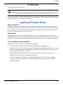
Lightning Protection Notice
What is the hazard?
A lightning strike into the ground causes an increase in the earth's potential causing a high voltage
potential between the centre conductor and shield of the coax cable. Voltages directly applied onto the
centre conductor "roll off" and arrive after the shield pulse producing a high voltage potential between
the centre conductor and shield of the coax cable.
Hazard Impact
A lightning strike causes the ground potential in the area to rise to dangerous levels resulting in
personnel harm or destruction of electronic equipment in an unprotected environment. It also conducts
a portion of the strike energy down the inner conductor of the coax cable to the connected equipment.
Actions to Mitigate Lightning Hazards
See also Figure 1 on Page 18 while reading these guidelines:
1.
Do not install the external antenna lines extra-building during a lightning storm.
2.
It is not possible to avoid overvoltages caused by lightning, but a lightning protection device may
be used to shunt a large portion of the transient energy to the building ground reducing the over
voltage condition as quickly as possible.
3.
Primary lightning protection must be provided by the operator/customer according to local
building codes as part of the extra-building installation.
4.
NovAtel recommends installing a secondary lightning protection device. The coaxial cable
entering the building is connected to protective ground through the primary and secondary
lightning protection.
DL-V3 User Manual Rev 3
17
Notice
4
2
1
3
5
5
5
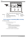
Figure 1: Primary and Secondary Lightning Protection
Reference
1
2
3
Description
Reference
Primary Lightning Protection Device
4
Secondary Lightning Protection Device
5
External Antenna
Description
OEMV Receiver
To Ground
Electromagnetic Compatibility (EMC) and Safety
DL-V3 Regulatory Testing
18
•
FCC, Part 15 Radiated Emissions, Class B
•
EN 55022 Emissions, Class B
•
EN 55024 Immunity
• EN 61000-4-2 Electrostatic Discharge Immunity
• EN 61000-4-3 Radiated RF EM Field Immunity Test
• EN 61000-4-4 Electrical Fast Transient/Burst Test
• EN 61000-4-6 Conducted Immunity
• EN 61000-4-8 Magnetic Field Immunity
•
EN 60950 Safety of Information Technology Equipment
DL-V3 User Manual Rev 3
Notice
WEEE Notice
If you purchased your OEMV family product in Europe, please return it to your dealer or supplier at
the end of its life. The objectives of the European Community's environment policy are, in particular,
to preserve, protect and improve the quality of the environment, protect human health and utilise
natural resources prudently and rationally. Sustainable development advocates the reduction of
wasteful consumption of natural resources and the prevention of pollution. Waste electrical and
electronic equipment (WEEE) is a regulated area. Where the generation of waste cannot be avoided, it
should be reused or recovered for its material or energy. WEEE products may be recognised by their
wheeled bin label (
). 1
RoHS Notice
The DL-V3 is compliant with the European Union (EU) Restriction of Hazardous Substances (RoHS)
Directive 2002/95/EC. 1
1.
Please visit the NovAtel website at http://www.novatel.com/support/weee.htm for more
information on WEEE and RoHS.
DL-V3 User Manual Rev 3
19
Customer Service
Customer Service
OEMV FIRMWARE UPGRADES
Firmware upgrades are firmware releases, which increase basic functionality of the receiver from one
model to a higher level model type. When available, upgrades may be purchased at a price, which is
the difference between the two model types on the current NovAtel GPS Price List plus a nominal
service charge.
WINLOAD
Please refer to the OEMV Family Installation and Operation User Manual for instructions on how to
use the WinLoad program to upgrade your PDC, PIC or OEMV-3 card.
CONTACT INFORMATION
Model upgrades are accomplished through NovAtel authorized dealers.
Contact your local NovAtel dealer first for more information. To locate a dealer in your area or if the
problem is not resolved, contact NovAtel Inc. directly using one of the following methods:
Call the NovAtel GPS Hotline at 1-800-NOVATEL (U.S. & Canada), or 403-295-4900 (international)
Fax: 403-295-4901
E-mail: [email protected]
Website: http://www.novatel.com
Write: NovAtel Inc., Customer Service Dept., 1120 - 68 Avenue NE, Calgary, AB., Canada, T2E 8S5
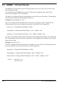
Before contacting NovAtel Customer Service regarding software concerns, please do the
following:
1. Issue a FRESET command
2. Log the following data to a file on your PC/laptop for 30 minutes
RXSTATUSB
RAWEPHEMB
RANGEB
BESTPOSB
RXCONFIGA
VERSIONB
once
onchanged
ontime 1
ontime 1
once
once
3. Send the file containing the logs to NovAtel Customer Service, using either the NovAtel ftp
site at ftp://ftp.novatel.com/incoming or the [email protected] e-mail address.
20
DL-V3 User Manual Rev 3
Foreword
Foreword
Congratulations!
Congratulations on your purchase of the DL-V3, a GNSS receiver with exceptional flexibility.
NovAtel is an industry leader in state-of-the-art GNSS receiver design. We believe that our DL-V3
will meet your high expectations, and are working hard to ensure that future products and
enhancements maintain that level of satisfaction.
This is your primary hardware and software reference.
Scope
This manual provides sufficient detail on the DL-V3 to allow you to effectively integrate and fully
operate it. The information in this manual supersedes DL-V3-related information in the DL-V3
Firmware Reference Manual, the OEMV Installation and Operation User Manual and its DL-V3
Addendum.
After the addition of accessories, an antenna and a power supply, the DL-V3 is ready to go.
The OEMV-3 in the DL-V3 utilizes a comprehensive user-interface command structure, which
requires communications through its communications (COM) ports. This manual describes the DLV3-specific commands and logs, see Commands starting on Page 81 and Logs starting on Page 147.
Other supplementary manuals, available on the accompanying CD and on our website at http://
www.novatel.com/support/docupdates.htm, aid you in using the other commands and logs available in
the OEMV family of receivers. This includes the OEMV-3 card within your DL-V3.
DL Explorer is also described, see Chapter 4 starting on Page 56. Integrated with the Control and
Display Unit (CDU) software, these programs provide graphical user interfaces to the DL-V3 for
logging, planning, transferring data files from the Compact Flash (CF) card to the PC/laptop,
upgrading, and converting data types.
Prerequisites
The installation chapters of this document provide information concerning the installation
requirements and considerations for DL-V3. To run the PC software supplied, your personal computer
must meet or exceed this minimum configuration:
Windows compatible mouse or pointing device and SVGA display
USB requires Windows 2000, or Windows XP
Although previous experience with Windows is not necessary to use the DL Explorer, familiarity with
certain actions that are customary in Windows will assist in the usage of the program. This manual has
been written with the expectation that you already have a basic familiarity with Windows.
DL-V3 User Manual Rev 3
21
Foreword
Conventions
Some simple conventions used in this manual are:
This is a notebox that contains important information before you use a command or log.
•
The letter H in the Offset columns of the commands and logs tables represents the
header length for that command or log. Refer to the OEMV Family Firmware
Reference Manual for ASCII and binary header details.
•
The number following 0x is a hexadecimal number.
•
Command descriptions’ brackets, [ ], represent the optionality of parameters.
•
In tables where values are missing they are assumed to be reserved for future use.
•
Status words are output as hexadecimal numbers and must be converted to binary
format (and in some cases then also to decimal). For an example of this type of
conversion, please refer to the RANGE log in the OEMV Family Firmware
Reference Manual.
Conversions and their binary or decimal results are always read from right to left.
For a complete list of hexadecimal, binary and decimal equivalents, please refer to
the Unit Conversion section of the GNSS Reference Book available on our website
at http://www.novatel.com/support/docupdates.htm.
See also Section B.1, Syntax Conventions on Page 84 for more syntax when entering commands.
22
DL-V3 User Manual Rev 3
Chapter 1
Introduction
The DL-V3 is a high-performance GNSS receiver capable of receiving and tracking different
combinations of GPS L1 C/A, L2C, L2 P(Y) and L5 code and carrier, GLONASS L1 and L2 code and
carrier, and L-Band (CDGPS and OmniSTAR) on a maximum of 72 channels. SBAS support is
standard and the DL-V3 adaptability offers multi-system, frequency, and size configurations for any
application requirement. Refer to the GNSS Reference Book for an overview of each of the above
signal types, available from our website at http://www.novatel.com/support/docupdates.htm. The DLV3’s front panel also features light emitting diodes (LEDs) for on the fly observations.
The DL-V3 is a triple-frequency GNSS receiver with integrated L-band capability but without the
need for a separate board. It is GLONASS-enabled with measurements, full code and RTK
positioning.
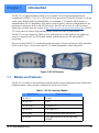
Once you connect the DL-V3 to an antenna and power supply, it begins operating as a fully functional
GNSS system. Figure 2 below shows the DL-V3 without an antenna or connecting cables.
Figure 2: DL-V3 Receiver
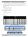
1.1
Models and Features
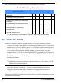
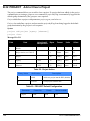
The DL-V3 is available in several different firmware models whose configurations may include other
additional features. Some possible configurations can be seen in Table 1.
Table 1: DL-V3 Controller Models
Model Name
Firmware Feature
DL-V3-L1
L1-only
DL-V3-L1L2
L1/L2
DL-V3-RT20
L1 plus RT-20
DL-V3-RT2
L1/L2 plus RT-2
DL-V3-VBS
L1 plus OmniSTAR VBS, and CDGPS
DL-V3-HP
L1/L2 plus OmniSTAR HP/XP/VBS, and
CDGPS
DL-V3 User Manual Rev 3
23
Chapter 1
Introduction
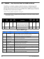
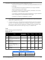
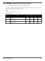
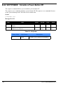
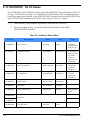
Table 2 lists the models, each capable of multiple positioning modes of operation:
Table 2: GPS Positioning Modes of Operation
DL-V3 Model
Modes of Operation a
L1
RT20
L1/L2
RT2
HP/
XP
VB
S
Single point
¸
¸
¸
¸
¸
¸
Pseudorange differential corrections
¸
¸
¸
¸
¸
¸
¸
¸
¸
¸
¸
¸
RT20 pseudorange and carrier-phase double
differencing
¸
RT2 pseudorange and carrier-phase double
differencing:
Post-processed RTK-type accuracy
¸
¸
¸
OmniStar HP/XP
¸
OmniStar VBS and CDGPS
¸
¸
¸
a. For a discussion on Positioning Modes of Operation, please refer to the OEMV Family
Installation and Operation User Manual.
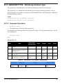
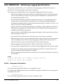
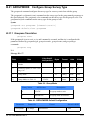
1.2
OPERATING MODES
The DL-V3 can either be controlled by a host computer or be set up for stand-alone operation.
•
Controlled Operation: A host computer can transmit logging parameters, receive collected data,
and turn the DL-V3 on or off. Whenever the DL-V3 is connected to a power source (regardless of
whether the DL-V3 is turned “on” or “off”), it detects if there is a host computer connected to one
of its serial ports. If a host computer is found, and there is serial port activity from a host
computer to the DL-V3, the DL-V3 powers up. If the DL-V3’s predefined POWERUP group, see
also Section 4.2.1, Receiver Groups on Page 57, exists in the DL-V3, the DL-V3 runs the
POWERUP group, otherwise the DL-V3 begins to search for satellites and waits for commands
from the host computer.
Only specific serial ports have wake-up capability on data activity. For example, the USB,
Ethernet or Bluetooth® ports do not.
•
Stand-Alone Operation: Once the DL-V3 receives configuration commands from a host
computer, it operates according to these parameters. For example, data collection can be
configured in advance by setting up a group to repeat continually.
Refer also to the OEMV Family Installation and Operation User Manual for information on receiver
communications and operation.
24
DL-V3 User Manual Rev 3
Chapter 2
Installation and Setup
This chapter contains instructions and tips to set up your DL-V3 to create a GNSS receiver system.
2.1
Additional Equipment Required
In order for the receiver to perform optimally, the following additional equipment is required:
•
A NovAtel GNSS antenna (user-supplied, NovAtel recommended)
•
A quality coaxial cable, and interconnect adapter cable as necessary (user-supplied)
•
A PC/laptop (user-supplied)
•
A means of communicating between the DL-V3 and PC/laptop
•
Serial null-modem cable (included with the receiver, NovAtel part number
01017658), see Figure 8, DB-9 Setup on Page 28
•
USB cable (user-supplied), see Figure 9, USB Setup on Page 28
•
Ethernet crossover cable (user-supplied), see Figure 11, Ethernet Setup on Page 29
•
Bluetooth link (user-supplied), see Figure 10, Bluetooth Setup on Page 29
Use a serial COM or USB connection to communicate with the receiver
first. This will give you the ability to configure the PC/laptop and DL-V3
before Ethernet or Bluetooth use.
•
A power supply (user-supplied)
•
A power cable (included with the receiver)
CAUTION:
2.1.1
When the DL-V3 is installed in a permanent location, such as in a building, it
should be protected by a lightning protection device according to local building
codes. See also Warranty on Page 15.
DL-V3 Setup
Complete the steps below to connect and power your DL-V3. See also Figures 8 to 11 starting on
Page 28.
1.
Mount a GNSS antenna on a secure, stable structure with an unobstructed view of the sky from
horizon to horizon, see Section 2.1.7, Mounting the GNSS Antenna on Page 32.
2.
Ensure a CF card is in the slot behind the door on the front face of the DL-V3. Open, or secure,
the door by turning the latch. See also Section 2.2.6, DL-V3 Removable Compact Flash Memory
Card starting on Page 39.
Once the CF card is installed, ensure that it is properly formatted, see
Page 39.
DL-V3 User Manual Rev 3
25
Chapter 2
3.
Installation and Setup
Use a coaxial cable to connect the antenna to the SAT ANT port, see Figure 3 below, which is
found on the back face of the DL-V3. See also Section 2.1.8, Connecting the Antenna to the
Receiver on Page 32.
Figure 3: Antenna Port
4.
Establish a physical communication connection between the DL-V3 and the PC/laptop
Either:
Connect COM1 on back of the DL-V3, see Figure 4 below, to a DB-9 serial
port on the PC/laptop
or:
Connect the USB port, see Figure 4, on the front of the DL-V3 to a USB port
on the PC/laptop (first install the USB drivers available on the CD provided),
see also Section 2.2.2, Universal Serial Bus (USB) starting on Page 34
Figure 4: COM1 Port (left) and USB Port (right)
The following types of connection can be made after initial communication and configuration
steps have been taken for either Bluetooth or Ethernet:
Either:
Connect the Ethernet port, see Figure 5 on Page 27, on the back of the DL-V3
to an Ethernet port on the PC/laptop. See also Appendix D, Ethernet
Configuration starting on Page 178
or:
Use Bluetooth communications, see Figure 6 on Page 27. See also Appendix E,
Bluetooth Configuration starting on Page 195
See also Section 2.1.10, Connecting Data Communications Equipment on Page 33.
26
DL-V3 User Manual Rev 3
Installation and Setup
Chapter 2
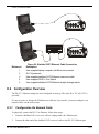
Figure 5: Ethernet Port
Figure 6: Bluetooth Interface at the Top of the DL-V3
5.
Line up the red mark on the power cable connector with the red mark of the INPUT 9-28 V
connector, see Figure 7 below, on the back of the DL-V3, and insert the power cable. See also
Section 2.1.9, Applying Power to the Receiver on Page 32.
Figure 7: Power Port
6.
Plug in the adapter and/or connect, turn on the power supply and press the
button on the front
face of the DL-V3. The power LED
on the front of the receiver glows green when the DL-V3
is turned on and is properly powered.
DL-V3 User Manual Rev 3
27
Chapter 2
Installation and Setup
Figure 8: DB-9 Setup
Figure 9: USB Setup
28
DL-V3 User Manual Rev 3
Installation and Setup
Chapter 2
Figure 10: Bluetooth Setup
Figure 11: Ethernet Setup
DL-V3 User Manual Rev 3
29
Chapter 2
2.1.2
Installation and Setup
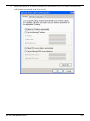
Installing the PC Utilities
Once the DL-V3 is connected to the PC/laptop, antenna, and power supply, install NovAtel’s PC
Utilities. These include CDU, a graphical user interface program.
1.
Start up the PC/laptop.
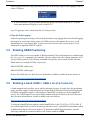
2.
Insert the accompanying CD, see Figure x below, in the CD-ROM drive of the computer.
3.
Select Install the OEMV GPS PC Utilities from the window that is automatically displayed. If the
window does not automatically open when the CD is inserted, select Run from the Start menu and
select the Browse button to locate Setup.exe on the CD drive.
Install the PC Utilities by advancing through the steps provided in the NovAtel PC Utilities setup
program.
Figure 12: OEMV CD
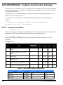
2.1.3
Selecting a GNSS Antenna
An active antenna is required because its low-noise amplifier (LNA) boosts the power of the incoming
signal to compensate for the line loss between the antenna and the receiver.
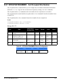
NovAtel offers a variety of single and dual-frequency GNSS antenna models, as indicated in Table 3
on Page 31. All include band-pass filtering and an LNA. The GNSS antenna you choose will depend
on your particular application. Each of these models offer exceptional phase-center stability as well as
a significant measure of immunity against multipath interference. Each one has an environmentallysealed radome. The ANT-532-C, ANT-533, ANT-534-C, ANT-536-C, ANT-537, ANT-538, GPS702L, GPS-701-GG, GPS-702-GG, GPS-701-GGL and GPS-702-GGL are RoHS compliant.
30
DL-V3 User Manual Rev 3
Installation and Setup
Chapter 2
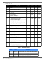
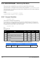
Table 3: NovAtel GNSS Antenna Models
Models
2.1.4
Frequencies Supported
GPS
GLONASS
701, 511, 521, 536, 537
L1 only
9
8
702, 532, 533
L1 and L2
9
8
702L, 534
L1 and L2 plus L-band
9
8
701GGL, 538
L1 plus L-band
9
9
701GG
L1 only
9
9
702GGL
L1 and L2 plus L-band
9
9
702GG
L1 and L2
9
9
Choosing a Coaxial Cable
An appropriate coaxial cable is one that matches the impedance of the antenna and receiver being used
(50 ohms), and whose line loss does not exceed 10.0 dB. If the limit is exceeded, excessive signal
degradation occurs and the receiver may not be able to meet its performance specifications. NovAtel
offers a variety of coaxial cables to meet your GNSS antenna interconnection requirements, including:
•
5, 15, or 30 m antenna cables with TNC male connectors on both ends (NovAtel
part numbers C006, C016 and C032 respectively)
Your local NovAtel dealer can advise you about your specific configuration. If your application
requires the use of cable longer than 30 m, refer to the application note RF Equipment Selection and
Installation on our website at www.novatel.com, or you can obtain it directly from NovAtel.
High-quality coaxial cables should be used because a mismatch in impedance, possible with lower
quality cable, produces reflections in the cable that increase signal loss. Though it is possible to use
other high-quality antenna cables, the performance specifications of the OEMV family receivers are
warranted only when used with NovAtel-supplied accessories.
2.1.5
Power Supply Requirements
This section contains information on the requirements for the input power to the receiver. See
Appendix A, Technical Specifications starting on Page 72 for more power supply specifications.
WARNING:
If the voltage supplied is below the minimum specification, the receiver will
suspend operation. If the voltage supplied is above the maximum specification,
the receiver may be permanently damaged, voiding your warranty.
The DL-V3 enclosure is supplied with a 12V power adapter with a built-in 3 A slow-blow fuse for use
with a standard 12 V DC power outlet. You can choose to press the DL-V3 power button or wait for
the power sequence, when it monitors the serial ports, as long as a valid voltage is present at the power
supply input, see DL-V3 Power Down and the Power Button on Page 33.
DL-V3 User Manual Rev 3
31
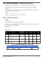
Chapter 2
Installation and Setup
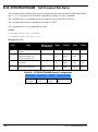
If a different supply is desired, the table below provides the input range and type of connector required
to mate with the enclosure’s power connector. The supply should be capable of 5 W.
Table 4: Enclosure Power Requirements
Enclosure
DL-V3
Power Cable Connector Required
4-pin LEMO socket connector a labelled PWR
Power Input Range
+9 to +28 V DC
a. See Appendix F, Replacement Parts on Page 200 for connector part numbers.
2.1.6
Mounting Bracket
A mounting kit is provided along with the DL-V3 to facilitate mounting the receiver to a surface.
The mounting kits are not designed for use in high-dynamics/vibration environments. Contact
NovAtel if your application needs the DL-V3 to be mounted in this type of environment.
To install the mounting bracket provided with the DL-V3, refer to the instructions provided with the
mounting kit.
2.1.7
Mounting the GNSS Antenna
The DL-V3 has been designed to operate with any of the NovAtel single-frequency or dual-frequency
GNSS antenna models. See Section 2.1.3, Selecting a GNSS Antenna on Page 30 for more
information.
When installing the antenna system:
2.1.8
•
Choose an antenna location that has a clear view of the sky so that each satellite
above the horizon can be tracked without obstruction. (Refer to the Multipath in the
GNSS Reference Book).
•
Mount the antenna on a secure, stable structure capable of safe operation in the
specific environment.
Connecting the Antenna to the Receiver
Connect the antenna to the receiver using high-quality coaxial cable, as discussed in Section 2.1.4 on
Page 31.
The DL-V3 provides a TNC female connector, see Figure 3 on Page 26, which can be connected to
the antenna directly with any of NovAtel’s coaxial cables.
2.1.9
Applying Power to the Receiver
Connect the power supply to the power port. For the DL-V3 you can choose to press its power button
or wait for the power sequence, see DL-V3 Power Down and the Power Button starting on Page 33.
See also Table 4, Enclosure Power Requirements on Page 32.
32
DL-V3 User Manual Rev 3
Installation and Setup
Chapter 2
DL-V3 Power Down and the Power Button
DL-V3 incorporates a power button on its front, see Figure 13 below. Pressing this switch, sends a
signal to the microprocessor to turn on or off the GNSS receiver.
Figure 13: Power Button
The DL-V3 has a low-power mode called power-down mode. To enter this low-power mode, press the
power button for at least three but no more than seven seconds, then release it. This is also the mode
the receiver enters into after applying power. In the power-down mode, all logging is disabled.
While power consumption in power-down (sleep) mode is minimal, less than 10 mA, the DL-V3 is
not completely off. If power conservation is important in your application, disconnect the power
source from the DL-V3 when it is not in use.
Press the power button momentarily to turn the DL-V3 back on. Also, the DL-V3 monitors its COM1
and COM2 serial ports. Power-up is triggered on these ports by a DC level of at least +5 V on either
RX or TX. The receiver does not detect activity on COM3. For example, if a key is pressed on a
handheld data logger that is plugged into COM1 or COM2, the time required to come on is only a few
seconds. However, it may require an additional few minutes to establish an initial time and position.
During power-down and power-up time, the serial ports do not process data. You must wait until the
receiver outputs an RXSTATUSA log with a BOOTOK message before typing any commands. Ensure
that your host application (especially Windows) does not poll these COM ports periodically to cause
an accidental power-up.
The automatic power-down feature is disabled when logging is in progress. However, if the power
button is pressed while the DL-V3 is logging data autonomously, the DL-V3 saves any open data files
and then goes into power-down mode.
An additional function of the power button is that it resets the DL-V3 if it is held depressed for at least
10 seconds. This system reset clears stored logging parameters and reverts to a factory configuration
when the power button is released.
2.1.10 Connecting Data Communications Equipment
In order to communicate with the receiver by sending commands and obtaining logs, a connection to
some form of data communications equipment is required. In the case of the DL-V3, your PC/laptop
can also communicate with the receiver using the Bluetooth interface. The default configuration
available is shown in Table 5, below, and its pin-out table is in Appendix A on Page 76.
Table 5: Default Serial Port Configurations
Receiver
COM1
COM2
COM3
AUX
USB
DL-V3
RS-232
RS-232
Bluetooth or Ethernet
RS-232
USB
DL-V3 User Manual Rev 3
33
Chapter 2
Installation and Setup
DL-V3 COM3 Configuration
The DL-V3 COM1, COM2 and AUX ports are RS-232-only but its COM3 port has Bluetooth/
Ethernet configuration options.
You can switch between Ethernet and Bluetooth on COM3 using the APPCONTROL command, see
Page 85. In the case of switching to Ethernet, power is automatically applied to it after switching.
Bluetooth, on the other hand, may be in sleep mode. If Bluetooth operation is required, it must be put
into active mode using the COMVOUT command, see Page 87. The Ethernet requires more setup
configuration steps. These involve configuring serial, and network, parameters. See Appendix D
starting on Page 178 for details.
If the receiver is turned off, or power is removed, the Ethernet or Bluetooth mode on COM3 is
returned to whichever mode was applied before power-down when it is powered up again.
2.2
Additional Features and Information
This section contains information on the additional features of the DL-V3, which may affect the
overall design of your receiver system.
2.2.1
Strobes
A set of inputs and outputs provide status and synchronization signals. These signals are referred to as
strobes. Not all strobe signals are provided on all receivers. However, for those products for which
strobes are available, you may want to design your installation to include support for these signals.
Pin-out information can also be found in Appendix A, DL-V3 Port Pin-Outs on Page 76
2.2.2
Universal Serial Bus (USB)
The DL-V3 receiver, along with the accompanying NovAtel USB drivers for Windows 2000 and
Windows XP, provides three virtual serial ports over a single USB 1.1 connection using USB D(+)
and USB D(-) signals, with a dedicated USB port labelled
.
The three virtual serial ports, identified as USB1, USB2, and USB3, are available to existing
Windows applications which use COM ports to communicate (for example, HyperTerminal and
CDU). The NovAtel USB drivers assign COM port numbers sequentially following any existing ports
on the PC/laptop. For example, if a PC/laptop has COM1 and COM2 ports, the NovAtel USB drivers
assign COM3 to USB1, COM4 to USB2, and COM5 to USB3.
Typically, a PC/laptop has several physical USB ports. The assignment of COM port numbers
is tied to a USB port on the PC/laptop. This allows you to switch receivers without Windows
assigning new COM ports. However, if you connect the receiver to a different physical USB
port, Windows detects the receiver's presence on that USB port and assigns three new COM
port numbers.
The NovAtel USB Configuration Utility installed with the NovAtel USB drivers allows you to change
the COM port numbers assigned to the virtual serial ports. The USB drivers, along with installation
34
DL-V3 User Manual Rev 3
Installation and Setup
Chapter 2
instructions, are available on the OEMV Family CD by selecting USB Support from the main menu.
You can also check for updates to the drivers or release notes on our website at www.novatel.com.
CAUTION
2.2.3
Do not connect USB ports if USB communications is not being used or you may
risk damaging your receiver.
Status Indicators
LED indicators on the DL-V3 provide the status of the receiver. They represent these categories:
• Power
• Receiver Status
• COMs (COM1, COM2 and AUX)
• COM3
• Satellite Tracking
• Flash Card Memory
• Positioning Mode
• Occupation Time
Power
The power indicator glows orange when the receiver is powered and then glows green once the
receiver has been turned on. See also DL-V3 Power Down and the Power Button on Page 33.
Status
The status indicator flashes orange when the receiver is first turned on. Under normal operation,
this LED is off. If a status event occurs, the LED flashes orange again. See also to the chapter on
Built-In Status Tests in the OEMV Family Installation and Operation User Manual and the
RXSTATUS log in the OEMV Family Firmware Reference Manual.
Communication Ports (excluding COM3)
The top of the COM1, COM2 and AUX LEDs flash GREEN when transmitting data while the
bottom of them flash AMBER when receiving data.
COM3
The COM3 section of the LED panel on the front of the DL-V3, has two LEDs:
• 1 for Bluetooth Mode
• 1 for Ethernet Mode
Only one mode may be used at a time on COM3. The active mode’s LED flashes blue for Bluetooth
and glows orange for Ethernet. If the receiver is turned off, or power is removed, the Ethernet or
Bluetooth mode on COM3 is returned to whichever mode was applied before power-down when it is
powered up again. See also Appendix D, Ethernet Configuration starting on Page 178.
DL-V3 User Manual Rev 3
35
Chapter 2
Installation and Setup
Satellite Tracking
The LED that is glowing, and its color, corresponds to the number of GPS-only, or GLONASS
and GPS-combined, satellites being tracked by the DL-V3, where the first LED to the left is #1,
see Table 6:
Table 6: Satellite Tracking LEDs
LED#
# of SVs
LED Color
1
≤3
Red
2
4 or 5
Amber
3
6 or 7
Green
4
8 or 9
Green
5
≥ 10
Green
Flash Card Memory
The number of LEDs that are glowing, and their colors, correspond to the amount of memory
left in the DL-V3’s compact flash card, where the first LED to the left is #1, see Table 7.
If all 5 flash card LEDs are flashing, it can mean that there is no compact flash card in the DLV3, or that the card in the unit is not formatted (see Section 2.2.6, DL-V3 Removable Compact
Flash Memory Card starting on Page 39).
Table 7: Flash Card Memory LEDs
# of LEDs
Capacity
LED Color
1
Capacity ≤ 20%
Red a
2
40% ≥ Capacity > 20%
Amber
3
60% ≥ Capacity > 40%
Green
4
80% ≥ Capacity > 60%
Green
5
Capacity > 80%
Green
a. This red LED can also mean that the card was not formatted, and
placed in the receiver, when the receiver was powered off.
Positioning Mode
Which LEDs are glowing, or blinking, or off, and their colors, correspond to the DL-V3’s
current positioning mode. Table 8, Positioning Mode LEDs on Page 37 shows the available
positioning modes and their corresponding LEDs where the first LED to the left is #1, as you
look at the DL-V3, and #5 is the furthest to the right. If the table cell shows the name of a color
(red, amber or green) with a solid background, that LED is glowing solidly. The table cells that
appear dim, behind their color name, indicate that the LED is flashing that color. The LED may
also be off.
36
DL-V3 User Manual Rev 3
Installation and Setup
Chapter 2
Table 8: Positioning Mode LEDs
Position Mode
Single Point
Differential GPS
OmniSTAR
Position Mode Detail a
1
2
3
4
5
Autonomous (fixed height)
Amber
Off
Off
Off
Off
Autonomous (3D)
Amber
Off
Off
Off
Off
SBAS
Off
Green
Off
Off
Off
CDGPS
Off
Off
Green
Off
Off
DGPS
Off
Green
Green
Off
Off
VBS (searching)
Amber
Green
Off
Off
Off
VBS (pulling in)
Amber
Green
Off
Off
Off
VBS
Amber
Green
Off
Off
Off
XP (searching)
Amber
Off
Green
Off
Off
XP (pulling in)
Amber
Off
Green
Off
Off
XP
Amber
Off
Green
Off
Off
HP (searching)
Amber
Green
Green
Off
Off
HP (pulling in)
Amber
Green
Green
Off
Off
HP
Amber
Green
Green
Off
Off
Amber
Off
Off
Green
Off
Float (RT-2)
Amber
Off
Off
Off
Green
Fixed (RT-2)
Amber
Off
Off
Off
Green
Float (RT-20)
RTK
b
a. If the table cell shows the name of a color (red, amber or green) with a solid background, that
LED is glowing solidly. The table cells that appear dim, behind their color name, indicate that the
LED is flashing that color. The LED may also be off.
b. If you have a GPS+GLONASS model, the same LED indication used for RT-20 GPS-only is used
for RT-20 GPS + GLONASS. The LEDs show the total number of satellites used in the solution
(GPS or GPS + GLONASS) without making a distinction between GPS and GLONASS. Check
the Constellation window in CDU for details on the availability of GPS and GLONASS satellites.
Refer also to CDU’s Help file.
DL-V3 User Manual Rev 3
37
Chapter 2
Installation and Setup
Occupation Time
The LED that is glowing green corresponds to the DL-V3’s occupation time gauge. The
occupation time LEDs provide an indication of whether sufficient data has been collected for
successfully post processing data for the indicated baseline. The LED that appears corresponds
to the baseline length that you can process your data to, where the first LED to the left is #1. The
occupation time gauge has the following values from left to right, see Table 9:
Table 9: Occupation Time LEDs
LED#
Baseline
Length
(km)
LED Color
1
≤5
Green
2
3
4
5
2.2.4
>5
≤ 10
> 10
≤ 15
> 15
≤ 20
≥ 20
Green
Green
Green
Green
External Oscillator
For certain applications requiring greater precision than what is possible using the on-board 20 MHz,
voltage-controlled, temperature-compensated crystal oscillator (VCTCXO), you may wish to connect
the DL-V3 to an external, high-stability oscillator. The external oscillator can be either 5 MHz or 10
MHz.
Operation consists of connecting a cable from the external oscillator to the DL-V3’s BNC external
oscillator port, labelled EXT OSC on the back of the DL-V3. See Figure 14 below. The receiver does
not have to be powered down during this procedure.
Figure 14: External Oscillator Port
Once the external oscillator has been installed, the EXTERNALCLOCK command (refer to the
OEMV Family Firmware Reference Manual) must be issued to define the clock model (for example,
cesium, rubidium or ovenized crystal). If the input clock rate is 5 MHz, the EXTERNALCLOCK
command must be issued to change the 10 MHz default rate.
38
DL-V3 User Manual Rev 3
Installation and Setup
2.2.5
Chapter 2
Antenna LNA Power
Receiver RF input gain requirements are easily met when using NovAtel antennas and coaxial cables.
NovAtel antennas employ a built-in, low-noise amplifier (LNA), which typically provides 26 dB of
gain to the received satellite signal. The power to the antenna LNA is provided through the center
conductor of the receiver’s RF port. To achieve the required input gain to the receiver, NovAtel
coaxial cables have been designed to exhibit no more than 6 dB loss.
CAUTION
2.2.6
NovAtel guarantees performance specifications only using NovAtel antennas.
DL-V3 Removable Compact Flash Memory Card
Data commands and logs can be recorded from the DL-V3 to a removable Compact Flash (CF) card.
The need for a companion handheld data logger is avoided when continuous user interaction is not
required, since the DL-V3 is capable of logging data according to pre-configured parameters without
any user intervention. In applications when continuous user interaction is required, a simple handheld
controller can be used with the DL-V3, as the controller does not require its own data logging
memory. The reduced handheld data logger or controller requirement simplifies your system and
reduce its total cost and power consumption. By default only a log group named default exists. A
powerup group must be created to take advantage of the automatic functionality, refer to Appendix
B, Commands starting on Page 81 for more information.
WARNING: To minimize the possibility of damage, always keep the CF card cover closed and
latched except when exchanging CF cards. Do not change the card while
logging is in progress. Data will be lost. It is not necessary to turn the receiver
off before inserting or extracting a CF card if you are not logging data.
An example of a 64 MB CF card is shown in Figure 15 below.
Figure 15: 64 MB Flash Card
When you insert a CF card into the DL-V3, enter a DISK FORMAT command using the Console
window in NovAtel’s Control and Display Unit (CDU) graphical user interface software. Wait a few
minutes and use the DL-V3 power button to turn it off and then on again. When power is returned, the
DL-V3 should be able to recognize and use the CF card. For more information on CDU refer to its online Help file.
DL-V3 User Manual Rev 3
39
Chapter 2
Installation and Setup
Data Logging
See Section 3.4, Using the DL-V3 starting on Page 51 to begin collecting data.
Collected data can either be transmitted to a host computer over a serial port, or stored on the CF card.
If you choose to log data to the CF card, each logging session is stored in a single, unique file. These
files can then be transferred to a host computer, for data analysis or other types of post-processing, by
one of two methods:
·
Transfer the data by means of serial communications, for example, DL Explorer in CDU
·
Physically remove the CF card from the DL-V3 and insert it into the host computer,
provided that it is also suitably equipped with a CF card port
See also the DL-V3 commands and logs, detailed in this manual.
Access Door
From Figure 16, Compact Flash Card Door (shown with its latch in the open position) on Page 40,
you can see that the CF card access door is closed with a latch (reference 1 in Figure 16). As long as
the latch is secured, it provides a water and dust-resistant seal around the CF card.
To open the CF card access door, turn the latch counter-clockwise, until it releases the door.
1
Figure 16: Compact Flash Card Door (shown with its latch in the open position)
To remove the CF card, unlock the access door. When the door is open, you can see an eject button to
the left of the card. You must push this button to partially eject the card. Grasp the card and pull it all
the way out.
WARNING: Do not change the card while logging is in progress. Data will be lost. It is not
necessary to turn the receiver off before inserting or extracting a CF card if you
are not logging data. See Step 4, Stop the Data Logging on Page 51.
To insert the card, ensure that it is correctly aligned before gently sliding it into the slot. When the card
slides all the way in and locks in place, the eject button extends. If you attempt to insert the card
incorrectly, it will not go all the way in, and the eject button will not extend. In this case, do not force
the card! Remove it, orient it properly, and then insert it. After the card is locked in place, close the
cover.
40
DL-V3 User Manual Rev 3
Installation and Setup
Chapter 2
The data logging mechanism is designed to be robust and to endure power interruptions (and similar
disruptive events) with minimum loss of data. In this situation, allow for your data to be possibly
reduced by several seconds up to a maximum of five minutes. When possible, error messages are
generated to identify problems as they arise. Refer also to the RXSTATUS log in the OEMV Family
Firmware Reference Manual.
Card Choice
You have the flexibility of choosing the CF card with the storage capacity that is the most appropriate
for your needs, based on the selected logging rate. This is discussed in greater detail in Section 3.4,
Using the DL-V3 starting on Page 51.
Take for example the case where you have to format and use a CF card (the DL-V3 comes with a 64
MB card but up to a 2 GB card is compatible):
At least 1% of free space must be available on the CF card to open a log file. On a 64 MB
disk, there is a 0.64 MB allowance for the file table.
Using CDU to Format the CF Card
1.
Establish a physical communication connection between the DL-V3 and the PC/laptop. Either
connect COM1 on the back of the DL-V3 to a DB-9serial port on the PC/laptop or connect the
USB port on the front of the DL-V3 to a USB port on the PC/laptop.
2.
Ensure the CF card is in its DL-V3 slot.
3.
Launch CDU and open the DL-V3 configuration, refer to CDU’s on-line Help for details.
4.
Select DL Explorer from the Tools menu in CDU. The DL Explorer window opens.
5.
Click on the CF Status button in the DL Explorer Window:
6.
Click on the Format button to format the CF card for use with the DL-V3. The format sequence
erases all data previously stored on the disk. This operation is not reversible and a warning
message is also shown:
The Format process closes all log files first. If a file transfer is in progress, it is stopped and then
the disk is formatted. The logs being logged to file are still present in the log list. The following
command can be entered in CDU’s Console window to remove them:
unlogall file
DL-V3 User Manual Rev 3
41
Chapter 2
Installation and Setup
Using HyperTerminal to Format the CF Card
1.
Establish a physical communication connection between the DL-V3 and the PC/laptop. Either
connect COM1 on the back of the DL-V3 to a DB-9serial port on the PC/laptop or connect the
USB port on the front of the DL-V3 to a USB port on the PC/laptop.
2.
Use HyperTerminal to open a communication connection through the USB or COM port.
a.
1.
42
Open the HyperTerminal program from the Start menu.
9600 bps is the default bits per second rate. The example above shows 115200. To
increase the connection rate, please connect the receiver using 9600 and then issue the
COM command to a set a higher rate. Refer to the COM command in the OEMV Family
Firmware Reference Manual.
2.
Baud rates higher than 115,200 bps are not supported by standard PC/laptop hardware.
Special PC hardware may be required for higher rates, including 230400 bps, 460800
bps, and 921600 bps.
3.
When connected using the USB port, the baud rate is ignored by the USB drivers and
instead the baud rate is as fast as possible. The current highest baud rate is 230400.
b.
Open the Properties dialog, select the ASCII Setup button in the Settings tab, check the Echo
typed characters locally check box, select OK and then OK again to return to the main
DL-V3 User Manual Rev 3
Installation and Setup
Chapter 2
HyperTerminal window. This enables you to view the characters you type.
3.
Type in LOG VERSION and press the <Enter> key to ensure you have a two-way serial connection with the DL-V3. If you do, a VERSION output message appears. For example:
4.
Ensure the CF card is in its DL-V3 slot.
5.
Type in DISK FORMAT and press the <Enter> key.
6.
Wait a minute and power off the DL-V3.
7.
Power on the DL-V3 again and the CF card is ready to use.
DL-V3 User Manual Rev 3
43
Chapter 3
Operation
Before operating the receiver for the first time, please ensure that you have followed the installation
instructions in Chapter 2, Installation and Setup starting on Page 25. The following instructions are
based on a COM port configuration such as that shown in Figure 17 on Page 48. It is assumed that a
personal computer, or laptop, is used during initial operation and testing for greater ease and
versatility.
3.1
Communications with the Receiver
Communication with the receiver typically consists of issuing commands through the communication
ports from an external serial communications device. This could be either a terminal or an IBMcompatible PC/laptop that is directly connected to the receiver serial port using a null-modem cable. If
you are using an RTK radio it connects to the receiver’s COM port by means of the radio serial cable
supplied with the receiver. It is recommended that you become thoroughly familiar with the
commands and logs detailed in the OEMV Firmware Reference Manual to ensure maximum
utilization of the receiver’s capabilities.
3.1.1
Serial Port Default Settings
The receiver communicates with your PC/laptop or terminal via a serial port. For communication to
occur, both the receiver and the operator interface have to be configured properly. The receiver’s
COM1, COM2 and COM3 default port settings are as follows:
•
9600 bps, no parity, 8 data bits, 1 stop bit, no handshaking, echo off
Changing the default settings requires using the COM command.
The data transfer rate you choose determines how fast information is transmitted. Take for example a
log whose message byte count is 96. The default port settings allows 10 bits/byte (8 data bits + 1 stop
bit + 1 framing bit). It therefore takes 960 bits per message. To get 10 messages per second then
requires 9600 bps. Please also remember that even if you set the bps to 9600 the actual data transfer
rate is lower and depends on the number of satellites being tracked, data filters in use, and idle time. It
is therefore suggested that you leave yourself a margin when choosing a data rate (115200 is
recommended for most applications).
CAUTION:
44
Although the receiver can operate at data transfer rates as low as 300 bps, this is
not desirable. For example, if several data logs are active (that is, a significant
amount of information needs to be transmitted every second) but the bit rate is set
too low, data will overflow the serial port buffers, cause an error condition in the
receiver status and result in lost data.
DL-V3 User Manual Rev 3
Operation
3.1.2
Chapter 3
Communicating Using a Remote Terminal
One method of communicating with the receiver is through a remote terminal. The receiver has been
pre-wired to allow proper RS-232 interface with your data terminal. To communicate with the
terminal the receiver only requires the RX, TX, and GND lines to be used. Handshaking is not
required, although it can optionally be used. Ensure the terminal’s communications set-up matches the
receiver’s RS-232 protocol. In the case of the DL-V3, Bluetooth and Ethernet are available.
3.1.3
Communicating Using a Personal Computer
An IBM-compatible PC/laptop can be set up to emulate a remote terminal as well as provide the
added flexibility of creating multiple-command batch files and data logging storage files. Any
standard communications software package that emulates a terminal can be used to establish
bidirectional communications with the receiver, for example, HyperTerminal or our own graphic user
interface (GUI) program, CDU. All data is sent as raw 8-bit binary or ASCII characters.
3.2
Getting Started
Included with your receiver are NovAtel’s CDU and Convert programs. CDU is a windows-based
GUI which allows you to access the receiver's many features without the need for communications
protocol or to write special software. The Convert utility is a windows-based utility that allows you to
convert between file formats, and strips unwanted records for data file compilation. See the DL-V3
quick start guide or installation.
3.2.1
Starting the Receiver
The receiver’s software resides in flash memory. When first powered, it undergoes a complete selftest. If an error condition is detected during a self-test, the self-test status word changes. This self-test
status word can be viewed in the header of any data output log. Refer to the chapter on Messages in
the OEMV Firmware Reference Manual for header information. If a persistent error develops, please
contact your local NovAtel dealer first. If the problem is still unresolved, please contact NovAtel
directly through on of the methods listed in the Customer Service section at the beginning of this
manual on Page 20.
3.2.2
Communicating with the Receiver Using CDU
Launch the CDU program and select Device | Open from its main menu. The Open Configuration
window appears. The example below shows an Open Configuration window with two possible
configurations already set up. Your configurations may be different or you may have none at all, in
which case, the Open Configuration window is empty.
DL-V3 User Manual Rev 3
45
Chapter 3
Operation
Refer to CDU’s Help file by selecting the Help | Contents menu. See also Chapter 4, DL Explorer
starting on Page 56 for details of CDU’s DL Explorer tool. Ensure you can see the Console and ASCII
Messages windows by selecting them from the View menu.
When the receiver is first turned on, no data is transmitted from the COM ports except for the port
prompt. The Console window displays a port name:
[COM1]
if connected to COM1 port,
[COM2]
if connected to COM2 port,
or
[COM3]
if connected to COM3 port
Any of the above prompts indicate that the receiver is ready and waiting for command input. The
screen may display other port names for other port types, for example USB1, USB2, USB3 or AUX.
1.
46
You may also have to wait for output from receiver self tests. For example, on start-up,
the OEMV family receiver is set to log the RXSTATUSEVENTA log ONNEW on all
ports. Refer to the OEMV Family Firmware Reference Manual for more details.
2.
If you find that CDU is unable to locate your OEMV family receiver, it may be that you
have previously used the SAVECONFIG command. In this case, try using a different
COM port to communicate to the receiver. Once communication has been established,
issue a FRESET STANDARD command. You should now be able to use your original
communication port again.
3.
XCOM1, XCOM2 and XCOM3 virtual ports can be generated by the receiver. However they
are unlikely to appear as a port prompt as you cannot connect to these types of ports using
CDU. Also, they are not available with the COM command but may be used with other
commands, such as INTERFACEMODE and LOG. Refer to the OEMV Firmware Reference
Manual for the virtual ports available and details on the above mentioned logs.
DL-V3 User Manual Rev 3
Operation
Chapter 3
Commands are typed at the interfacing computing device’s keypad or keyboard, and executed after
issuing a carriage return command which is usually the same as pressing the <Enter> key.
An example of a response to an input command is the FIX POSITION command. It can be as:
[COM2] fix position 51.11635 -114.0383 1048.2 [carriage return]
<OK
where [COM2] is the port prompt, followed by the command you enter from your keypad or keyboard
and [carriage return] indicates that you should press the <Enter> key.
The above example illustrates command input to the base receiver’s COM2 port which sets the
position of the base station receiver for differential operation. Confirmation that the command was
actually accepted is the appearance of <OK.
If a command is entered incorrectly, the receiver responds with:
<INVALID MESSAGE ID
WARNING!:
3.3
(or a more detailed message)
Ensure the Control Panel’s Power Settings on your PC/laptop are not set to go
into Hibernate or Standby modes. Data will be lost if one of these modes occurs
during a logging session.
Transmitting and Receiving Corrections
Corrections can be transmitted from a base station to a rover station to improve position accuracy. The
base station is the GNSS receiver which is acting as the stationary reference. It has a known position
and transmits correction messages to the rover station. The rover station is the GNSS receiver which
does not know its exact position and can be sent correction messages from a base station to calculate
differential GNSS positions. An example of a differential setup is given in Figure 17 on Page 48.
DL-V3 User Manual Rev 3
47
Chapter 3
Operation
Rover
Base
2
1
5
3
4
4
12V
Figure 17: Basic Differential Setup
Reference
Description
1
A DL-V3 receiver for the rover station
2
NovAtel GNSS antenna
3
User-supplied data storage device to COM1
4
User-supplied power supply
5
User-supplied radio device to COM2
6
A DL-V3 receiver for the base station
7
User-supplied PC/laptop, for setting up and monitoring, to COM1
See also Appendix D, Ethernet Configuration starting on Page 178 for Ethernet and
Appendix E, Bluetooth Configuration starting on Page 195 for Bluetooth configuration
options.
System biases can introduce errors, as described in the Modes of Operation chapter in the OEMV
Family Installation and Operation User Manual. In most cases you need to provide a data link
between the base station and rover station (two NovAtel receivers) in order to receive corrections.
SBAS and L-band corrections can be accomplished with one receiver and are exceptions to the base/
rover concept. Generally a link capable of data throughput at a rate of 9600 bits per second, and less
than 4.0 s latency, is recommended.
Once your base and rover are set up, you can configure them as shown in the configuration examples
that follow in Sections 3.3.1 - 3.3.2 starting on Page 50.
48
DL-V3 User Manual Rev 3
Operation
3.3.1
Chapter 3
Base Station Configuration
At the base station, enter the following commands:
interfacemode port rx_type tx_type [responses]
fix position latitude longitude height
log port message [trigger [period]]
For example:
RTCA
interfacemode com2 none rtca off
fix position 51.11358042 -114.04358013 1059.4105
log com2 rtcaobs ontime 1
log com2 rtcaref ontime 10
log com2 rtca1 ontime 5
log com2 rtcaephem ontime 10 1
RTCM
(optional)
interfacemode com2 none rtcm off
fix position 51.11358042 -114.04358013 1059.4105
log com2 rtcm3 ontime 10
log com2 rtcm22 ontime 10 1
log com2 rtcm1819 ontime 1
log com2 rtcm1 ontime 5
RTCMV3
interfacemode com2 none rtcmv3 off
fix position 51.11358042 -114.04358013 1059.4105
log com2 rtcm1006 ontime 10
log com2 rtcm1003 ontime 1
CMR+
interfacemode com2 none cmr off
fix position 51.11358042 -114.04358013 1059.4105
log com2 cmrobs ontime 1
log com2 cmrplus ontime 1
CMR
(important to use ontime 1 with cmrplus)
interfacemode com2 none cmr off
fix position 51.11358042 -114.04358013 1059.4105
log com2 cmrobs ontime 1
log com2 cmrref ontime 10
log com2 cmrdesc ontime 10 1
DL-V3 User Manual Rev 3
49
Chapter 3
3.3.2
Operation
Rover Station Configuration
At the rover station, enter:
interfacemode port rx_type tx_type [responses]
For example:
RTCA
interfacemode com2 rtca none off
RTCM
interfacemode com2 rtcm none off
RTCMV3
interfacemode com2 rtcmv3 none off
CMR+
interfacemode com2 cmr none off
CMR
interfacemode com2 cmr none off
3.3.3
(same as CMR+)
Configuration Notes
For compatibility with other GNSS receivers, and to minimize message size, it is recommended that
you use the standard form of RTCA, RTCM, RTCMV3 or CMR corrections as shown in the base and
rover examples above. This requires using the INTERFACEMODE command to dedicate one
direction of a serial port to only that message type. When the INTERFACEMODE command is used
to change the mode from the default, NOVATEL, you can no longer use NovAtel format messages.
If you wish to mix NovAtel format messages and RTCA, RTCM, RTCMV3 or CMR messages on the
same port, you can leave the INTERFACEMODE set to NOVATEL and log out variants of the
standard correction messages with a NovAtel header. ASCII or binary variants can be requested by
simply appending an "A" or "B" to the standard message name. For example on the base station:
interfacemode com2 novatel novatel
fix position 51.11358042 -114.04358013 1059.4105
log com2 rtcm1b ontime 2
Using the receiver in this mode consumes more CPU bandwidth than using the native
differential messages as shown in Section 3.3.1, Base Station Configuration on Page 49.
At the rover station you can leave the INTERFACEMODE default settings (interfacemode com2
novatel novatel). The rover receiver recognizes the default and uses the corrections it receives with a
NovAtel header.
The PSRDIFFSOURCE and RTKSOURCE commands set the station ID values which identify the
base stations from which to accept pseudorange or RTK corrections respectively. They are useful
commands when the rover station is receiving corrections from multiple base stations. Refer to the
GNSS Reference Book for more information on SBAS, available from our website at:
http://www.novatel.com/support/docupdates.htm
All PSRDIFFSOURCE entries fall back to SBAS (even NONE) for backwards compatibility.
50
DL-V3 User Manual Rev 3
Operation
Chapter 3
At the base station it is also possible to log out the contents of the standard corrections in a form that is
easier to read or process. These larger variants have the correction fields broken out into standard
types within the log, rather than compressed into bit fields. This can be useful if you wish to modify
the format of the corrections for a non-standard application, or if you wish to look at the corrections
for system debugging purposes. These variants have "DATA" as part of their names (for example,
RTCADATA1, RTCMDATA1, CMRDATAOBS, and more). Refer also to the OEMV Firmware
Reference Manual, which describes the various message formats in more detail.
Information on how to send multiple commands and log requests using DOS or Windows, can
be found on our website at http://www.novatel.com/support/knowledgedb.htm.
3.4
Using the DL-V3
A group is a set of logs for the receiver. The default software configuration for group information
includes a group named default. A powerup group must be created to take advantage of the automatic
logging functionality.
Upon acquisition of coarse time, if a group named powerup exists, the DL-V3 executes the group
automatically.
The FRESET command allows you to reset the DL-V3 to its factory default settings. SITEDEF logs,
refer to the DL-V3 Firmware Reference Manual, contain site record information. For example:
#SITEDEFA,COM1,0,61.0,FINESTEERING,1420,316947.028,00180020,e40c,2678;
0,"","DLV3ii",0,0.000000000,"",1420,1420,316890.000,316935.000,00000000,0*c56c1a5d
3.4.1
Log Data from a Site to a File
Consider the case of logging data at a site and appending filename and other information. The
following steps apply to a base or rover site. For the base, you only need to log one file per session.
1.
2.
There is no need to continually start and stop logging if you are using post-processing
software, where it is dealt with automatically.
Ensure your antenna is in the correct position at the base and rover.
To log a group and update the site information
1.
Select the Group
2.
Edit the Site
3.
Start the Data Logging
4.
Stop the Data Logging
DL-V3 User Manual Rev 3
51
Chapter 3
Operation
1. Select the Group
The the DL-V3 captures sets of logs using log groups. You create a group in CDU’s DL Explorer and
then upload the group to the DL-V3.
CDU is available from our website at: http:// www.novatel.com/support/fwswupdates.htm.
Launch CDU from the Start menu folder specified during the installation process. The default location
is Start | Programs | NovAtel OEMV | CDU. Launch CDU and open, or create, a DL-V3
configuration, refer to your DL-V3 Quick Start Guide. Select DL Explorer in the Tools menu and then
select the Edit DL Groups... button. Within the DL Groups dialog, you can change a log group name
by clicking on it and editing it directly. In the Logs tab, select the log to add from the Name drop-down
list. Select the log format using the Format drop-down list (ASCII or Binary). Select the trigger for
the log using the Trigger drop-down list. If you choose the On Time trigger, select the period for
logging using the Period drop-down list or type it in. Select OK to add the new log to the log group.
To log to file, select File from the Port drop-down list.
2. Edit the Site
In the DL Explorer dialog, select a group name from the left panel and select the Site tab. Check the
Automatically Log Site on Startup and the Include Site Information checkboxes. Then enter a site
name or number, and the height of the antenna ‘lip’ from the site you are measuring.
Place the tape measure from the lip to where the tip of the antenna pole touches the
ground (do not measure straight down). The slant from the edge of the antenna is
different than when the measurement is straight down.
Add 33 mm to the measured reading. This makes up for the distance of the antenna
element to the lip on NovAtel 700-series antennas.
Click OK for your input to take effect and return you to the main DL Explorer window.
You can now log a site and the site information is written to the log file.
3. Start the Data Logging
Once a log group has been created, it can be uploaded to the DL-V3. The steps below provide details
on uploading a group.
In the DL Explorer window, select the Group Management button.
Select the group to upload to the DL-V3 from the list of groups in the CDU panel of the dialog.
Select the UpLoad button to copy the group.
52
DL-V3 User Manual Rev 3
Operation
Chapter 3
Select a group in the DL Groups panel and press Start on the dialog’s right to start logging to your CF
card or COM port.
A red cross beside a log group name indicates the group is not active in the DL-V3. A green
check mark indicates the group is active in the DL-V3.
Up to 5 log groups can be stored in the DL-V3 at any one time.
4. Stop the Data Logging
In the Group Management dialog, click on the Stop button to stop logging data. Once the data logging
has stopped, it is no longer writing to the card. While you move the antenna, the receiver is still
functioning but it is not logging data. To start a new site at a new location, repeat steps #1 to #4.
Information is appended to the CF card file.
3.5
Enabling SBAS Positioning
All OEMV family receivers are capable of SBAS positioning. This positioning mode is enabled using
the SBASCONTROL command. On a simulator, you may want to leave the testmode parameter off or
specify NONE explicitly. The following commands are typically used to enable WAAS and other
SBAS modes, for example EGNOS, respectively:
SBASCONTROL enable waas
SBASCONTROL enable egnos
Refer to the GNSS Reference Book for more information on SBAS, available from our website at:
http://www.novatel.com/support/docupdates.htm
3.6
Enabling L-band (OEMV-1, OEMV-3, DL-V3 & ProPak-V3)
L-band equipped receivers allow you to achieve sub-meter accuracy. In order to use this positioning
mode, you must enable L-band tracking to the Canada-Wide Differential Global Positioning System
(CDGPS) or OmniSTAR signal. A subscription to OmniSTAR is required to use the OmniSTAR
service. The CDGPS signal is free and available without subscription. Refer to the GNSS Reference
Book for more information on L-band, available from our website at:
http://www.novatel.com/support/docupdates.htm.
To obtain an OmniSTAR subscription, contact OmniSTAR at 1-800-338-9178 or 713-785-5850. If
you contact OmniSTAR, you will be asked to provide the receiver’s OmniSTAR serial number (which
is different from the NovAtel serial number). To obtain the OmniSTAR serial number, enter the
following command in a terminal window or the Console window in CDU:
DL-V3 User Manual Rev 3
53
Chapter 3
Operation
log lbandinfo
The log that is generated displays the L-band serial number in the fifth field following the log header.
It is a six digit number in the range 700000 to 799999. This log also provides the status of your
subscription. Refer to the LBANDINFO command for more information.
In order to activate an OmniSTAR subscription, the receiver must be powered and tracking an L-band
satellite. When advised by OmniSTAR of the appropriate satellite frequency and data link rate for
your location, use the ASSIGNLBAND command to configure your receiver. The CDGPS frequencies
can also be used with the ASSIGNLBAND command. Below are examples for using either CDGPS or
OmniSTAR:
assignlband cdgps 1547547 4800
assignlband omnistar 1536782 1200
1.
In addition to a NovAtel receiver with L-band capability, a subscription to the
OmniSTAR, or use of the free CDGPS, service is required. Contact NovAtel for details.
OmniSTAR website: http://www.omnistar.com/
1.
CDGPS website: http://www.cdgps.com/
2.
The frequency assignment can be made in Hz or kHz. For example:
Hz:
assignlband omnistar 1536782000 1200
kHz:
assignlband omnistar 1536782 1200
A value entered in Hz is rounded to the nearest 500 Hz.
To confirm you are tracking an L-band signal, log the L-band status information by entering the
following command:
log lbandstat
For example, if you are receiving CDGPS, the fifth field after the header should be 00c2:
lbandstat com1 0 43.5 finesteering 1295 149951.671 00000000 976f 34461
<1547546977 46.18 4541.0 0.00 00c2 00f0 0 0 0 8070 0001 0 0 0
Please refer to the LBANDSTAT command in the OEMV Family Firmware Reference Manual for
details.
3.7
Pass-Through Logging
The pass-through logging feature enables the GNSS receiver to redirect any ASCII or binary data that
is input at a specified COM port or, if available, USB port to any specified receiver COM or USB port.
This capability, in conjunction with the SEND command, can allow the receiver to perform bidirectional communications with other devices such as a modem, terminal, or another receiver.
There are several pass-through logs. PASSCOM1, PASSCOM2, PASSCOM3, PASSXCOM1,
54
DL-V3 User Manual Rev 3
Operation
Chapter 3
PASSXCOM2, PASSXCOM3, PASSUSB1, PASSUSB2, PASSUSB3 and PASSAUX are available
on OEMV family receivers for logging through serial ports. The AUX port is available on OEMV-3based products. Refer to the PASSCOMx log for details.
3.8
T Sync Option
The T Sync Option section of the OEMV Installation and Operation User Manual describes the
relationship constraints of the input signal phase when the Time Synchronization Modification (T
Sync Mod) option has been added to an OEMV-3-based product (this includes DL-V3).
When an external oscillator is connected, T Sync pulses are sent through hardware on the receiver
card and cannot be disabled. You must issue a time-synchronization-enabling command (refer to
ADJUST1PPS TIME in the OEMV Family Firmware Reference Manual) for the receiver to track
properly.
DL-V3 User Manual Rev 3
55
Chapter 4
DL Explorer
DL Explorer is a powerful program which allows you to edit log groups, upload these groups to a DLV3 and download data from the CF card to your PC/laptop. DL Explorer is easy to use and learn,
while still providing a wide range of features and flexibility.
4.1
Basic Operations
4.1.1
Starting DL Explorer
DL Explorer is under the Tools menu in CDU. If you accepted the default installation path, CDU can
start from the Windows Start menu, by selecting Programs | NovAtel OEMV | CDU. Otherwise, select
the path where you installed CDU.
Launch CDU and open, or create, a DL-V3 configuration. Refer to the Establishing Receiver
Communication section of your DL-V3 Quick Start Guide that was included with your receiver. Refer
also to CDU’s Help menu.
Select DL Explorer in the Tools menu to see the DL Explorer main window as shown in Figure 18, DL
Explorer Main Window on Page 56.
Baud rates higher than 115,200 bps are not supported by standard PC/laptop hardware.
Special PC hardware may be required for higher rates, including 230400 bps, 460800 bps,
and 921600 bps.
Figure 18: DL Explorer Main Window
56
DL-V3 User Manual Rev 3
DL Explorer
4.1.2
Chapter 4
Exiting DL Explorer
To exit DL Explorer, click the
button in the upper right-hand corner of the main window or press
<Alt> + <F4> on your keyboard.
4.2
Receiver Operations
DL Explorer can communicate with the DL-V3 to establish data collection groups.
The DL-V3 can collect several types of data. A group is a profile that tells the receiver what type of
data to collect, at what rate the data should be collected and where the data should be stored (for
example, to the CF card). Use the POWERUP group for automatic data collection on start-up.
4.2.1
Receiver Groups
To start logging data, you must create a group profile and transfer it to the DL-V3. When configuring
your group profile, you can define the group settings to determine the type of information the DL-V3
collects. These group profiles consist of the log type, the data destination, the trigger, period and a
description for each log within the group.
To edit a group, click on the Edit DL Groups... button:
.
The DL Groups dialog appears. An example is shown in Figure 19, DL Groups Dialog on Page 57.
Figure 19: DL Groups Dialog
The DL Groups panel, to the left of the dialog, displays the names of the current groups including
DL-V3 User Manual Rev 3
57
Chapter 4
DL Explorer
groups you defined, and the preset POWERUP group provided by DL Explorer. The POWERUP
group can be modified from the software, see Section , Preset POWERUP Group, on Page 60.
Edit a group name by clicking on it directly in the left side panel. Add a new group using the
button, remove a group using the
button or duplicate a group using the
button.
Group names are converted to all uppercase lettering.
The default group name (other than the preset POWERUP group name) is GROUPX where X is the
next possible number to make the name unique in the DL Groups dialog (for example, GROUP1). The
group name can be changed but must be unique. Group names can be up to eight characters long but
the first character of the name cannot be a number.
A receiver group consists of information in five tabs:
• Logs
See the Logs Tab section on Page 58
• Position
See the Position Tab section on Page 60
• Site
See the Site Tab section on Page 61
• Interface
See the Interfaces Tab section on Page 63
• COM Port
See the Ports Tab section on Page 64
Click the OK button to save your changes or the Cancel button to discard your changes and return to
the main DL Explorer window.
Logs Tab
To add a log to a group, select the Logs tab.
Figure 20: Add Log
Select a log from the Name drop down box.
58
DL-V3 User Manual Rev 3
DL Explorer
Chapter 4
Select a destination from the Port list:
• COM1, COM2, COM3 Send this log through a receiver COM port
• AUX
Send this log through a receiver AUX port
• USB1, USB2, USB3
Send this log through a receiver USB port
• FILE
Save this log to the receiver’s CF card
• NO_PORTS
No port specified
• THISPORT
Current COM port
If the group is intended for use in a stand-alone mode of operation, choose FILE to save the logs to the
DL-V3’s internal CF card. You can save ASCII or binary format logs to the FILE destination.
Choose a log output format from the Format list, ASCII or binary.
The trigger and period settings can be edited by using the fields in the Trigger and Period sections of
the Logs tab.
A log’s trigger and period information is what determines when and how often the DL-V3 receiver
collects that log’s information. For example, if the trigger and period for the compressed range
measurements log (RANGECMP) is set to OnTime 2, the receiver logs compressed range
measurements every two seconds. For 2 Hz (twice per second), use an OnTime 0.5 trigger.
To edit trigger information for a particular log, first select a trigger from the Trigger drop down box.
The Period drop down box appears dim unless OnTime is selected as the trigger. In this case, you can
edit the number of seconds directly or choose a time period from the Period drop down box. Table 10
explains your choices.
Table 10: Log Triggers
Trigger
Description
ontime
You specify when the receiver should collect the information. For example, if you
specify On Time 5, the information is collected every 5 seconds.
onchanged
Output only if the message changes. For example, if you select the almanac log
(RAWALMB), you can choose the On Changed option so when a log group is run,
the receiver collects almanac information once and not again unless the almanac
information changes.
once
Output only the current message.
onnew
Output when the message is updated (not necessarily changed).
onnext
Output only the next message.
Click on the Add button to add the log details to the group. Continue to add logs until your group
contains the logs you want. To remove a log from the group, select the log in the Logs table, and click
on the Remove button.
To edit a log in a receiver group, select it, change the settings and click on the Add button again. The
log appears twice in the table. Select the log with the old settings and click on the Remove button.
Click the OK button to save your changes or the Cancel button to discard your changes. The logs you
have selected are displayed along with their descriptions, default destination and interval settings.
DL-V3 User Manual Rev 3
59
Chapter 4
DL Explorer
Preset POWERUP Group
Your DL Explorer software is set up with a preset receiver group. Below is an outline of the
POWERUP group. The group name, the logs within the group and the interval options are displayed
(see details on editing trigger and interval information on Page 59).
Use this group when you are working with a receiver that is an RTK base and you want to postprocess the data. You might also use this group for automatic data collection on the receiver.
Type of Information
Description
almanacb onchanged
current almanac
ionutcb onchanged
ionospheric and UTC clock parameters
rangecmpb ontime
10.0
compressed channel range measurements
rawephemb
onchanged
raw ephemeris
rtcaobs ontime 1.0
base station GPS data output every second
rtcaref ontime 10.0
base station position output every 10 seconds
The first four types of information (almanac, ionutc, rangecmp and rawephem) are
typically used for post processing and are logged to the CF card. The last two (rtcaobs
and rtcaref) are typically used for an RTK base station and are transmitted from COM2.
Position Tab
The second tab in the DL Groups dialog is the Position tab, see Figure 21 on Page 61. Click in one of
the radio buttons that give you the option of having no position information, known fixed position
information (a static point) or single-point averaging information.
If you choose No Position Information then the Position tab’s Known Position and Position Average
edit boxes appear dim. If you choose Fixed Known Position then you must enter position information
(latitude, longitude and ellipsoidal height) in the Known Position fields.
60
DL-V3 User Manual Rev 3
DL Explorer
Chapter 4
Figure 21: Position Tab
For the Fixed Averaged Position option, the Position Average fields become editable so you can enter
the criteria by which you would like the position averaging to stop.
Position averaging stops either before a certain time period in minutes (a maximum of 60 and a
minimum of 1.5 minutes), if the standard deviation for the horizontal axis (in meters) has been met, or,
for example, if the standard deviation for the vertical axis (in meters) has been met. The typical
standard deviation range is from 10 cm (3.9") to 5 m (16.4’). The position is fixed to the position
averaged at that site.
Site Tab
The Site tab is the third tab available in the DL Groups dialog, see Figure 22 on Page 62. It enables
you to control whether site information is specified for sites automatically logged on startup.
DL-V3 User Manual Rev 3
61
Chapter 4
DL Explorer
Figure 22: Site Tab
If you check the Automatically Log Site on Startup check box, the group mode is set to static, a SITE
ENTER command, see Page 135, is executed on startup, and the site is configured with parameters
from the Site Information panel (if the Include Site Information check box is also selected), or with a
default site name. If the Automatically Log Site on Startup check box is not checked, the group mode
is set to kinematic.
Static
A method of GNSS data collection that involves simultaneous observations between
stationary receivers. Post-processing computes the vector between sites.
Kinematic Your GNSS antenna is moving. Kinematic data collection requires only short periods
of data observations. Operational constraints include starting from, or determining,
a known baseline and tracking a minimum of four satellites. One receiver is statically
located at a control site, while others are moved between sites to be measured.
If do you wish to enter specific site information and have the information included in the group
definition, check the Include Site Information check box. The editable fields are:
• Antenna Model
Enter the model number for your antenna.
• Antenna Height
Enter the vertical antenna height above ground.
• Antenna Number
Enter your antenna’s serial number.
• Site Number
Enter a number for this site.
• Site Name
Enter a site name.
If the Site Name field is left blank, the log file name is used as the site name.
The group definition issued during the group upload includes the GROUPANTHEIGHT,
GROUPANTSN, GROUPANTTYPE, GROUPSITENAME, and GROUPSITENUMBER. See Pages
62
DL-V3 User Manual Rev 3
DL Explorer
Chapter 4
97, 98, 99, 116, and 117 respectively for further details on these commands.
You may need to edit the following fields from their default values depending on your application:
Minimum Satellites
Select a number from 1 to 9 for the minimum number of satellites,
where the default is 4.
Elevation Mask
Choose an integer value for the elevation mask angle between 0
and 90 degrees, where the default is 0.
Interfaces Tab
The Interfaces tab, in the DL Groups dialog, is shown in Figure 23:
Figure 23: Interfaces Tab
This tab allows you to specify what type of data a particular port on the DL-V3 can transmit and
receive. Click directly in any of the cells and a drop down box of choices is available The receive type
(Receiver) tells the receiver what type of data to accept on the specified port. The transmit type
(Transmitter) tells the receiver what kind of data it can generate. For example, you would set the
receive type on a port to RTCA in order to accept RTCA differential corrections.
The Ports and Interfaces tabs are originally blank when the user creates a group (in case you don’t
want to alter the receiver ports and interface configurations when you start logging a group).
Otherwise the DL-V3 might drop the connection with CDU when the settings are changed.
Click on the Add Defaults button to add the default values for interfaces. To remove the values (for
example, so as not to interfere with CDU), click on the Remove All button.
You can set the base station ID, when it is transmitting corrections, in the DGPS TX ID field. The
following range values should be used when you are entering a base ID:
RTCA ID: any four character string containing only alpha (a through z) or numerical (0 - 9)
characters
DL-V3 User Manual Rev 3
63
Chapter 4
DL Explorer
0 ≤ RTCM ID ≤ 1023
0 ≤ CMR ID ≤ 31
The default entry for the DGPS Tx Id field is ANY. The ANY option forces the message to revert to its
default base ID. The ANY defaults are:
RTCM
0
RTCA
AAAA
CMR
0
It is also possible to disable or enable the generation or transmission of command responses for a
particular port. Disabling of responses is important for applications where data is required in a specific
form and the introduction of extra bytes may cause problems, for example RTCA, RTCM or CMR.
Disabling a port prompt is also useful when the port is connected to a modem or other device that
responds with data the receiver does not recognize.
When NONE is chosen, the specified port is disabled from interpreting any input or output data.
Therefore, no commands or differential corrections are decoded by the specified port.
Ports Tab
The last tab in the DL Groups dialog is the Ports tab as seen in Figure 24 on Page 64:
Figure 24: Ports Tab
This tab allows you to specify the setting for each COM port and the AUX port. The defaults for the
POWERUP group are shown in Figure 24, Ports Tab on Page 64. You can also turn on/off ports by
checking (on) or unchecking (off) their check boxes in the Powered column.
The Ports and Interfaces tabs are originally blank when the user creates a group (in case you don’t
want to alter the receiver ports and interface configurations when you start logging a group).
Otherwise the DL-V3 might drop the connection with CDU when the settings are changed.
64
DL-V3 User Manual Rev 3
DL Explorer
Chapter 4
Click on the Add Defaults button to add the default port values. To remove the values (for example, so
as not to interfere with CDU), click on the Remove All button.
4.3
DL Explorer Receiver Communications
You can use the DL Explorer utility to manage and transfer files or groups between the CF card in the
DL-V3 and your PC/laptop.
4.3.1
Communication Parameters
Click on the Port Settings button,
communication parameters:
in the main DL Explorer window, to view the current
Figure 25: COM Parameters
WARNING!:
1.
2.
CDU is already connected to the receiver. If you change these settings, CDU will
lose its connection.
When connected using the USB port, the baud rate is ignored by the USB drivers and instead
the baud rate is as fast as possible.
The current highest baud rate shown in DL Explorer is 230400.
DL-V3 User Manual Rev 3
65
Chapter 4
4.3.2
DL Explorer
Upload Group from the PC/Laptop to the Receiver
Click on the
button in the main DL Explorer window and the Group Management dialog
appears, see Figure 26.
Figure 26: Group Management
The Group Management dialog displays the current default group table on the PC/laptop in the CDU
Groups panel on the left. The groups stored on the connected receiver are in the DL Groups panel on
the right. If the receiver is not connected, or if there are no groups loaded onto the DL-V3, the DL
Groups panel is empty.
Up to five groups at a time can be selected for upload from your PC/laptop to the receiver. To upload
a group, highlight it in the CDU Groups panel.
Select the UpLoad button to copy the group.
Select a log group in the DL Groups panel and click on the Start button to start logging to the CF card.
The Starting Groups dialog appears, see Figure 27 on Page 67. Specify the default port to use and a
name for the log file. If you leave the Log Filename field empty, a sequential filename is created. If
the Port field for the group is set to NO_PORTS in the Logs tab of the DL Groups dialog, see Logs
Tab on Page 58-59, the Start process uses the port you select in the Starting Groups dialog. Otherwise,
logs using a specific port are not affected by an entry in the Default Port field.
66
DL-V3 User Manual Rev 3
DL Explorer
Chapter 4
Figure 27: Starting Groups
The Stop button in the Group Management dialog becomes active while the DL-V3 is logging the
data. Click on the Stop button to stop the DL-V3 from logging the chosen log group. Only one log
group may be started at a time.
A red cross beside a log group name indicates the group is not active in the DL-V3. A green
check mark indicates the group is active in the DL-V3.
When there are groups in the DL Groups panel, you can also download them to CDU. To download
groups to CDU, highlight them in the DL Groups panel and click on the Download button. The groups
are downloaded to CDU and may then be seen in the CDU Groups panel.
To refresh the data displayed in the DL Groups panel, click on the Refresh button. Delete groups from
the DL-V3 by first highlighting them and then clicking on the Delete button. To delete all the groups
on the DL-V3, click on the Delete All button. There is no need to highlight any groups in the DL
Groups panel in this case.
Files are stored on the CF card but groups are stored in the DL-V3’s NVM.
DL-V3 User Manual Rev 3
67
Chapter 4
4.3.3
DL Explorer
Transfer a File from the DL-V3 to the PC/Laptop
Ensure that your PC/laptop and DL-V3 are communicating, see Section 4.3.1, Communication
Parameters on Page 65.
Click on the
Figure 26.
button in the main DL Explorer window and the Logs Transfer dialog appears, see
Figure 28: Log Transfer Dialog
The Logs Transfer dialog displays the files stored on the connected receiver. To check the details on a
file, click on the File Details button. A File Details information window pops up, see Figure 29 on
Page 69. Once you have reviewed the file details, click on the OK button to return you to the Logs
Transfer dialog.
68
DL-V3 User Manual Rev 3
DL Explorer
Chapter 4
Figure 29: File Details
To transfer a file from the CF card to your PC/laptop, first edit the destination in the Local Folder field
at the bottom of the Logs Transfer dialog using the Browse... button. Then select a file by highlighting
it in the Logs Transfer panel. You can select one or multiple files at a time. Click on the Download
button. A progress window pops up until the file is downloaded, see Figure 30 below.
Figure 30: Download Progress Bar
The selected files are transferred to your PC/laptop.
If, when you try to transfer a file to the PC/laptop, a filename already exists in the directory on the PC/
laptop, you are prompted with the dialog File Already Exists. This dialog enables you to reply with the
following options:
DL-V3 User Manual Rev 3
69
Chapter 4
DL Explorer
<Overwrite> .......this option enables you to replace the current file on the PC/laptop with the new file
from the receiver
<Rename>...........this options enables you to give a different name to the file that you are transferring
to the PC/laptop
<Cancel>.............this option cancels the file transfer to the PC/laptop
To refresh the files on your CF card, click on the Refresh button. To delete a file from the CF card,
select it and click on the Delete button. To delete all the files on the CF card, click on the Delete All
button. There is no need to highlight any files in this case.
4.3.4
Flight Recorder
The DL-V3 can record the receiver’s hardware status and satellite tracking data. The Flight Recorder
is not on by default. You must request it.
To request a flight record, click on the
button in the main DL Explorer window. The Flight
Recorder dialog appears, see Figure 31 below.
Figure 31: Flight Recorder: OFF
Click in the Report HW and/or the Report Tracking check boxes in the Reporting Options section (at
least one option should be selected before recording) of the Flight Recorder dialog. Click on the Start
button to start recording. The Start button appears dim while flight recording is in progress, see Figure
32 below.
Figure 32: Flight Recorder: ON
70
DL-V3 User Manual Rev 3
DL Explorer
Chapter 4
The debuglog.bin file stores the results of your recording. Click on the
Explorer window to see it.
Click on the
recording.
1.
2.
4.3.5
button in the DL
button in the DL Explorer window. Then click on the Stop button to stop the
If you quit CDU, flight recording continues until you click on the Stop button in CDU's
Flight Recorder window.
You can download the debuglog.bin file after you stop the flight recorder.
CF Card Status
To find out the status of the CF card, click on the
button in the main DL Explorer window. The
CF Card Status window appears as shown in Figure 33, CF Card Status on Page 71:
Figure 33: CF Card Status
Click on the Format button to format the CF card for use with the DL-V3. The format sequence erases
all data previously stored on the disk. This operation is not reversible and a warning message is also
shown.
The Format process closes all log files first. If a file transfer is in progress, it is stopped and then the
disk is formatted. The logs being logged to file are still present in the log list. The following command
can be entered in CDU’s Console window to remove them: unlogall file.
DL-V3 User Manual Rev 3
71
Appendix A
A.1
Technical Specifications
OEMV Family Receiver Performance
PERFORMANCE (Subject To GPS System Characteristics)
Position Accuracy
a
Standalone:
L1 only
L1/L2
b
SBAS
DGPS
RT-20
RT-2
b
CDGPS
OmniSTAR:
VBS
XP
HP
Post Processed
Time To First Fix
1.8 m RMS
1.5 m RMS
0.6 m RMS
0.45 m RMS
0.20 m RMS
0.01 m + 1 ppm RMS
0.6 m RMS
0.7 m RMS (OEMV-1 and OEMV-3 only)
0.15 m RMS (OEMV-3 only)
0.10 m RMS (OEMV-3 only)
5 mm + 1 ppm RMS
Hot: 30 s (Almanac and recent ephemeris saved and approximate position)
Warm: 40 s (Almanac, approximate position and time, no recent ephemeris)
Cold: 50 s (No almanac or ephemeris and no approximate position or time)
Reacquisition
0.5 s L1 (typical)
1.0 s L2 (typical) (OEMV-2 and OEMV-3 only)
Data Rates
Raw
Measurements:
20 Hz
Computed
Position:
20 Hz
OmniSTAR HP
Position:
20 Hz (OEMV-3 only)
Time Accuracy
ac
20 ns RMS
Velocity Accuracy
0.03 m/s RMS
Measurement Precision
C/A code phase 6 cm RMS
L1 carrier phase:
Differential
0.75 mm RMS
L2 P code
25 cm RMS (OEMV-2 and OEMV-3 only)
L2 carrier phase:
Differential
2 mm RMS (OEMV-2 and OEMV-3 only)
Dynamics
a.
b.
c.
d.
72
Velocity
Height
d
515 m/s
18,288 m d
Typical values. Performance specifications are subject to GPS system characteristics, U.S. DOD operational degradation,
ionospheric and tropospheric conditions, satellite geometry, baseline length and multipath effects.
GPS-only
Time accuracy does not include biases due to RF or antenna delay.
In accordance with export licensing.
DL-V3 User Manual Rev 3
A.2
DL-V3 Specifications
INPUT/OUTPUT CONNECTORS
Antenna Input
TNC female jack, 50 Ω nominal impedance
+4.75 to +5.10 V DC, 100 mA max
(output from DL-V3 to antenna/LNA)
PWR
4-pin LEMO connector
+9 to +28 V DC at 3.5 W (typical while logging) a
In-rush power consumption: 8 A for less than 120 μs b
COM1
COM2
COM3
AUX
I/O
OSC
DB9P connector
DB9P connector
Bluetooth v1.1 interface or Ethernet c
DB9P connector
DB9S connector
BNC connector (external oscillator)
NOVATEL PART NUMBER
DL-V3
01017829
LED INDICATORS
More details can also be found in Section 2.2.3, Status Indicators starting on Page 35
Power
Orange: receiver is powered
Green: receiver is turned on
Status
Orange flash: at start-up
Off: normal operation
Orange flash again: status event
COM1/COM2/ AUX
Green flash (top): transmitting
Amber flash (bottom): receiving
COM3
Blue: Bluetooth active
Orange: Ethernet active
Satellite Tracking
Positioning Mode
LED#
# of
SVs
LED
Color
1 (left)
≤3
Red
2
4 or 5
Amber
3
6 or 7
Green
4
8 or 9
Green
5 (right)
≥ 10
Green
See Table 8, Positioning Mode LEDs on Page 37
Continued on Page 74
DL-V3 User Manual Rev 3
73
LED INDICATORS (CONTINUED)
Flash Card Memory
# of
LEDs
LED
Color
Capacity
1
Capacity ≤ 20%
2
40% ≥ Capacity > 20%
Red a
Amber
3
60% ≥ Capacity > 40%
Green
4
80% ≥ Capacity > 60%
Green
5
Capacity > 80%
Green
a.This red LED can also mean that the card was
not formatted, and placed in the receiver,
when the receiver was powered off.
Occupation Time
LED#
Baseline
Length (km)
LED
Color
1 (left)
≤5
Green
2
>5
≤ 10
> 10
≤ 15
> 15
≤ 20
3
4
5 (right)
≥ 20
Green
Green
Green
Green
PHYSICAL
Size
185 x 163 x 76 mm
Weight
1.3 kg maximum (including OEMV-3 card)
ENVIRONMENTAL
Operating Temperature
-40°C to +75°C
Storage Temperature
-45°C to +95°C
Humidity
Not to exceed 95% non-condensing
Vibrationd
Random
Sinusoidal
Shock
MIL-STD-810F
IEC 68-2-6
IEC 68-2-27
a. When tracking GPS satellites
b. Occurs approximately 7 s after power is applied
c. COM3 may be configured for Bluetooth or Ethernet but only one communication mode
at a time can be used on COM3. Ethernet usage also requires a change of cable. See also
the APPCONTROL command in the DL-V3 Firmware Reference Manual and Appendix
D, Ethernet Configuration on Page 178 of this manual.
d. See also the Notice section of this manual starting on Page 16.
74
DL-V3 User Manual Rev 3
DIMENSIONS
ab
a. All dimension are in millimeters, please use the Unit Conversion section of the GNSS
Reference Book for conversion to imperial measurements.
b. See also the ProPak-V3 Dimensions section, in Appendix A of the OEMV Family Installation
and Operation User Manual, for the dimensions of the mounting bracket. The mounting
bracket also has a set of instructions that come with it.
DL-V3 User Manual Rev 3
75
A.2.1
Port Pin-Outs
Table 11: DL-V3 Serial Port Pin-Out Descriptions
Connector
Pin No.
COM1
RS-232
COM2
RS-232
AUX
RS-232
1
N/C
N/C
N/C
2
COM1_Rx
COM2_Rx
COM3_Rx
3
COM1_Tx
COM2_Tx
COM3_Tx
4
N/C
POUT
POUT
5
GND
GND
GND
6
N/C
N/C
N/C
7
RTS1
RTS2
RTS3
8
CTS1
CTS2
CTS3
9
N/C
N/C
N/C
Table 12: DL-V3 I/O Port Pin-Out Descriptions
Connector Pin No.
76
Signal Name
Signal Descriptions
1
VARF
Variable frequency out
2
PPS
Pulse per second
3
MSR
Mark 1 output
4
EVENT1
Mark 1 input
5
PV
Valid position available
6
EVENT2
Mark 2 input, which requires a pulse longer than 150 ns is
7
_RESETOUT
Reset TTL signal output to an external system. Active low.
8
ERROR
Indicates a fatal error when high.
9
GND
Digital ground
pulled up to 5V through a 47kΩ resistor in the DL-V3.
Refer also to the MARKCONTROL command in the
OEMV Firmware Reference Manual.
DL-V3 User Manual Rev 3
A.2.2
Cables
A.2.2.1
12V Power Adapter Cable (NovAtel part number 01017663)
The power adapter cable supplied with the DL-V3, see Figure 34 below, provides a convenient means
for supplying +12 V DC while operating in the field.
Input is provided through the standard 12V power outlet. The output from the power adapter utilizes a
4-pin LEMO connector (LEMO part number FGG.0B.304.CLAD52Z) and plugs directly into the
PWR input located on the back panel of the DL-V3.
This cable is RoHS compliant.
For alternate power sources please see Section 2.1.9 on Page 32.
9
1 (-)
4 (-)
2 (+)
3 (+)
10
-
1
2
3
4
+
+
-
5
6
7
8
11
12
13
Reference
1
2
3
4
9
10
11
Description
Reference
Black
Red
Orange
Brown
Connector key marking
12V adapter
Spring
5
6
7
8
12
13
Description
Ground
12V
12V
Ground
Universal tip
6 Amp slow-blow fuse
Figure 34: DL-V3 Power Cable
DL-V3 User Manual Rev 3
77
A.2.2.2
Null-modem Cable (NovAtel part number 01017658)
This cable supplied with the DL-V3, see Figure 35 below, provides an easy means of communications
with a PC/laptop. The cable is equipped with a 9-pin connector at the receiver end which can be
plugged into the COM1, COM2, or AUX port. At the PC/laptop end, a 9-pin connector is provided to
accommodate a PC/laptop serial (RS-232) communication port.
This cable is RoHS compliant.
1
5
9
1
5
6
9
6
11
Wiring Table:
Connector
Pin Number
To DB9S (10)
2
3
8
7
4
5
1&6
To DB9S (11)
3
2
7
8
1&6
5
4
Reference
10
11
Description
DB9S (Female)
DB9S (Female)
Figure 35: DL-V3 Null-Modem Cable
78
DL-V3 User Manual Rev 3
A.2.2.3
Straight Through Serial Cable (NovAtel part number 01017659)
This cable can be used to connect the DL-V3 to a modem or radio transmitter to propagate differential
corrections. The cable is equipped with a female DB9 connector at the receiver end. The male DB9
connector at the other end is provided to plug into your user-supplied equipment (please refer to your
modem or radio transmitter user guide for more information on its connectors). The cable is
approximately 2 m in length. See Figure 36 below.
This cable is RoHS compliant.
5
1
9
6
1
5
6
9
11
1
2
3
4
5
6
7
8
9
1
2
3
4
5
6
7
8
9
Reference
10
11
Description
Reference
DB9P (male) connector
DB9S (female) connector
12
Description
9-conductor cable
Figure 36: DL-V3 Straight Through Serial Cable
DL-V3 User Manual Rev 3
79
A.2.2.4
I/O Strobe Port Cable (NovAtel part number 01017660)
The strobe lines on the DL-V3 can be accessed by inserting the male DB9 connector of the I/O strobe
port cable into the I/O port. The other end of this cable is provided without a connector to provide
flexibility. The jacket insulation is cut away slightly from the end but the insulation on each wire is
intact. The cable is approximately 2 m in length. See Figure 37 below.
This cable is RoHS compliant.
5
1
9
6
1
2
3
4
5
6
7
8
9
Wiring Table:
I/O Port
Pin
I/O Port
Signal
I/O Port Cable
Wire Color
I/O Port
Pin
I/O Port
Signal
I/O Port Cable
Wire Color
1
VARF
Black
6
Event2
2
PPS
Brown
7
_RESETOUT Blue
3
MSR
Red
8
ERROR
Violet
4
Event1
Orange
9
GND
White/Grey
5
PV
Yellow
Reference
10
Description
DB9P (male) connector
Reference
11
Green
Description
9-conductor cable
Figure 37: DL-V3 I/O Strobe Port Cable
80
DL-V3 User Manual Rev 3
Appendix B
Commands
The DL-V3 firmware implements the commands in Table 13 (repeated in Table 14 on Page 82 in the
order of their binary messages IDs), in addition to the OEMV family command set. The LOG
command is available to all OEMV receivers but is an essential command to do any logging. It is
included in this appendix for your convenience.
Table 13: DL-V3 Commands in Alphabetical Order
Message ID
ASCII Command
Description
781
appcontrol
Switch between Ethernet and Bluetooth on COM3
779
comvout
Control the peripheral power supply on specific COM ports
185
currentfile
Specify a file for FILEHDR and FILETRANSFER requests
186
currentgroup
Specify a group for GROUPDEF requests
53
del
Delete files from the CF Card
284
disk
Carry out CF card maintenance
67
extcontrol
Disable POWERUP group execution on start-up
20
freset
Factory reset
54
group
Modify log group definitions
66
groupantheight
Edit the antenna height for the group
55
groupantsn
Edit the serial number for the group
65
groupanttype
Edit the antenna type for the group
755
groupcom
Associate one or more port configurations with a group
753
groupcomvout
Control power on specified COM ports for the group
271
groupdgpstxid
Edit the DGPS base ID configuration for the group
56
groupecutoff
Edit the elevation cut-off configuration for the group
58
groupfixpos
Fix the receiver position when the group is executed
318
groupinterfacemode
Edit the interface mode configuration for the group
64
grouplog
Modify message-logging specifications in a group
57
groupmode
Configure the survey type for a group survey
63
grouppossave
Configure position averaging when the group is executed
62
groupsatlimit
Edit the satellite limit configuration for the group
59
groupsitename
Edit the site name for the group
61
groupsitenumber
Edit the site number for the group
149
groupuse
Group configuration macro to execute DL-V3 commands
Continued on Page 82
DL-V3 User Manual Rev 3
81
Message ID
ASCII Command
Description
1
log
Request logs from the receiver
157
logfile
Manual file logging control
163
methumid
Specify air humidity
164
metpress
Specify air pressure
165
mettemp
Specify ambient temperature
211
project
Project-related parameters
201
rename
Rename a file stored in the CF Card
18
reset
Perform a hardware reset
212
satlimit
Specify the minimum number of satellites to use in the
position solution
166
site
Control site occupations
167
siteupdateantheight
Configure occupied site’s antenna height information
168
siteupdateanttype
Configure site antenna type information for an occupied site
169
siteupdateattribute
Configure site attribute information for an occupied site
170
siteupdatename
Configure site name information for an occupied site
171
siteupdatenumber
Configure site number information for an occupied site
213
softpower
Power-button OFF simulation
257
write
Create logs containing user data
204
writefile
Create files or append data to an existing file on the CF Card
where the data format is char
240
writefilehex
Create files or append data to an existing file on the CF Card
where the data format is hexbytes
205
writehex
Create logs containing user data
Table 14: DL-V3 Commands in Order of their Message IDs
Message ID
ASCII Command
Description
1
log
Request logs from the receiver
18
reset
Perform a hardware reset
20
freset
Factory reset
53
del
Delete files from the CF Card
54
group
Modify log group definitions
55
groupantsn
Edit the serial number for the group
56
groupecutoff
Edit the elevation cut-off configuration for the group
Continued on Page 83
82
DL-V3 User Manual Rev 3
Message ID
ASCII Command
Description
57
groupmode
Configure the survey type for a group survey
58
groupfixpos
Fix the receiver position when the group is executed
59
groupsitename
Edit the site name for the group
61
groupsitenumber
Edit the site number for the group
62
groupsatlimit
Edit the satellite limit configuration for the group
63
grouppossave
Configure position averaging when the group is executed
64
grouplog
Modify message-logging specifications in a group
65
groupanttype
Edit the antenna type for the group
66
groupantheight
Edit the antenna height for the group
67
extcontrol
Disable POWERUP group execution on start-up
149
groupuse
Group configuration macro to execute DL-V3 commands
157
logfile
Manual file logging control
163
methumid
Specify air humidity
164
metpress
Specify air pressure
165
mettemp
Specify ambient temperature
166
site
Control site occupations
167
siteupdateantheight
Configure occupied site’s antenna height information
168
siteupdateanttype
Configure site antenna type information for an occupied site
169
siteupdateattribute
Configure site attribute information for an occupied site
170
siteupdatename
Configure site name information for an occupied site
171
siteupdatenumber
Configure site number information for an occupied site
185
currentfile
Specify a file for FILEHDR and FILETRANSFER requests
186
currentgroup
Specify a group for GROUPDEF requests
201
rename
Rename a file stored in the CF Card
204
writefile
Create files or append data to an existing file on the CF Card
where the data format is char
205
writehex
Create logs containing user data
211
project
Project-related parameters
212
satlimit
Specify the minimum number of satellites to use in the
position solution
213
softpower
Power-button OFF simulation
240
writefilehex
Create files or append data to an existing file on the CF Card
where the data format is hexbytes
Continued on Page 84
DL-V3 User Manual Rev 3
83
Message ID
ASCII Command
Description
257
write
Create logs containing user data
271
groupdgpstxid
Edit the DGPS base ID configuration for the group
284
disk
Carry out CF card maintenance
318
groupinterfacemode
Edit the interface mode configuration for the group
753
groupcomvout
Control power on specified COM ports for the group
755
groupcom
Associate one or more port configurations with a group
779
comvout
Control the peripheral power supply on specific COM ports
781
appcontrol
Switch between Ethernet and Bluetooth on COM3
The arguments for each of these commands are described in the following sections.
For a complete listing and description of the other commands that the DL-V3 is capable of processing,
please refer to the OEMV Family Firmware Reference Manual.
B.1
SYNTAX CONVENTIONS
The following rules apply when entering commands, at the command prompt, from a keyboard.
84
1.
Courier font is used to illustrate program output or user input.
2.
References to other commands, logs or any of their fields are shown in italics.
3.
The commands are not case sensitive. For example, you could type either METTEMP 0 or
mettemp 0.
4.
Except where noted, either a space or a comma can separate commands and their required entries.
For example, you could type either group del alpha p20a or
group,del,alpha,p20a.
5.
At the end of a command, a carriage return is required. For example, press <Enter> or <Return>
on your keyboard.
6.
Responses are provided to indicate whether or not an entered command was accepted. The format
of the response depends on the format of the command. Refer to the OEMV Family Firmware
Reference Manual for more information.
7.
Optional parameters are indicated by square brackets ( [ ] ). For commands that contain
optional parameters, the value used if the optional parameter is not specified is given in the syntax
table for the command.
8.
Data format definitions, as specified in the “Format” field, are detailed in the OEMV Family
Firmware Reference Manual. Note that all binary data is little-endian byte-ordered.
DL-V3 User Manual Rev 3
B.2
APPCONTROL
COM3 Bluetooth/Ethernet Switch
Use the appcontrol command to switch between Ethernet and Bluetooth on COM3.
Use the appcontrol option 12 9 command to restore Ethernet settings back to their defaults1:
IP:
192.168.1.223
Mask:
255.255.255.0
DHCP: OFF
The APPCONTROL OPTION 12 9 command triggers a receiver RESET and, on startup, restores the
Ethernet defaults.
The APPCONTROL OPTION 12 1 command resets the XPORT-AR Ethernet device. This does not
restore the Ethernet defaults. The Ethernet device settings are persistent until you issue a FRESET or
APPCONTROL OPTION 12 9 command, see above.
When COM3 uses Bluetooth, the baud rate is set to 115200. When COM3 is switched to Ethernet, the
baud rate is still 115200.
1.
2.
When the DL-V3 is in Bluetooth range, your computer can recognize it and is able to
access it using this password: 0000 (four zeroes).
If the receiver is turned off, or power is removed, the Ethernet or Bluetooth mode on COM3
is returned to whichever mode was applied before power-down when it is powered up again.
Syntax
appcontrol function param1 [param2 [param3 [param4]]]
Message ID = 781
Field
Data
Value Used if
Not Specified
1
Header
-
2
Application control function
BLUETOOTH
3
Application control parameter 1, see Table 16
and the examples that follow
4
Bytes
Format
Units
Offset
-
-
0
4
Enum
none
H
0
4
Enum
none
H+4
Application control parameter 2 (for future use)
0
4
Ulong
none
H+8
5
Application control parameter 3 (for future use)
0
4
Ulong
none
H+12
6
Application control parameter 4 (for future use)
0
4
Ulong
none
H+16
1.
See also the Ethernet Configuration appendix starting on Page 178.
DL-V3 User Manual Rev 3
85
Table 15: Application Functions
Binary
ASCII
Description
0
BLUETOOTH
Use BLUETOOTH followed by either 0 or 1 of the
Application Parameters, see Table 16, to select
either Bluetooth or Ethernet
8
OPTION
Use OPTION followed by 12 and then 9, from
Table 16, to restore the Ethernet settings defaults.
Table 16: Application Parameters
Binary
ASCII
0
Select Bluetooth application
1
Select Ethernet application
9
Restore Ethernet settings I
Examples:
To switch back to Bluetooth on COM3, issue this command:
APPCONTROL BLUETOOTH 0
To switch COM3 from Bluetooth to Ethernet, issue this command:
APPCONTROL BLUETOOTH 1
To restore Ethernet settings to their defaults and reset the receiver, issue this command:
APPCONTROL OPTION 12 9
To reset the XPORT-AR Ethernet device but not restore the Ethernet settings’ defaults:
APPCONTROL OPTION 12 1
86
DL-V3 User Manual Rev 3
B.3
COMVOUT
Control COM Peripheral Power
The comvout command allows you to control the peripheral power supply on specific COM ports.
It supports COM2, COM3 and AUX. No power is supplied for peripheral ports when the receiver is
turned off. COM3 does not have a power pin and there is no direct access to COM3.
The comvout command enables (on) or disables (off) the supply of power to the specified port. For
COM2, and AUX, power is turned on or off to the power pin associated with each port. The comvout
command specified for COM3 puts the Bluetooth device to sleep (low power mode), or turns off the
Ethernet device completely, when comvout is set to OFF. The Bluetooth device wakes up from sleep
mode when comvout is set to ON.
Peripheral power is disabled in all cases while the receiver is turned off (if COM2 power is enabled,
COM2 power is disabled while the receiver is off, and is enabled again when the receiver is on).
Also, the COM3 peripheral is off when the receiver is off. This applies to Bluetooth and Ethernet.
Refer to the DL-V3 power specifications in Appendix A of the OEMV Installation and Operation User
Manual.
Syntax
comvout com2|com3|aux on|off
Message ID = 779
Field
Value Used if
Not Specified
Data
Bytes
Format
Units
Offset
-
-
0
1
Header
-
2
Serial port identifier, see Table
17
-
4
Enum
none
H
3
Action, see Table 18 on Page 88
ON
4
Enum
none
H+4
Table 17: COM Serial Port Identifiers
Binary
ASCII
Description
1
Not used in this command a
2
COM2
COM port 2
3
COM3
COM port 3
6-15
Not used in this command a
16
AUX
AUX port
17
Not used in this command a
a. Refer to the OEMV Family Firmware Reference
Manual for other port identifiers. If an identifier
other than COM2, COM3 or AUX is used with this
command, it returns an error.
DL-V3 User Manual Rev 3
87
Table 18: COM Voltage Out Action
Binary
88
ASCII
Description
0
OFF
Set state to off
1
ON
Set state to on
2
Reserved
3
DEFAULT
Do not change the COMVOUT state.
This option only applies to the
GROUPCOMVOUT command. Refer
also to the GROUP command in the
DL-V3 Firmware Reference Manual.
DL-V3 User Manual Rev 3
B.4
CURRENTFILE Specify File for FILEHDR/FILETRANSER Logs
The currentfile command allows you to specify a file to which subsequent requests for filehdr and
filetransfer logs apply, see Pages 158-160.
Specified without arguments, the currentfile command clears any previously configured currentfile
settings. The currentfile file command:
•
Configures the currentfile to file. File is a name of a file on the CF card specified in a base.ext
format, where base is a maximum of 8 characters and the optional ext is a maximum of 3
characters. Subsequent requests for the filehdr log, see Page 158, displays the filehdr log read
from file or for the filetransfer log, see Page 160, transfers file in filetransfer log packets.
•
Causes the receiver to transfer the entire file on all subsequent requests for the filetransfer log
when issued with the dump mode specified as all.
•
Causes the receiver to transfer only file packet number packet_id on all subsequent requests for
the filetransfer log when issued with the transfer mode specified as {single [packet_id]}.
Packet_id ranges from 0 to SizePackets-1, see the dirent log on Page 154. The first packet is
numbered 0. Packet size is defined in the file log definition.
•
Defaults the dump mode to all when issued without specifying the dump mode.
Syntax
currentfile
currentfile file [all|{single [packet_id]}]
Message ID = 185
Field
Value Used if
Not Specified
Data
Bytes
Format
Units
Offset
-
-
0
1
Header
-
2
File
-
12
Char[]
none
H
3
Dump Mode, see Table 19
ALL
4
Enum
none
H+12
4
Packet ID
0
4
Ulong
none
H+16
Table 19: Dump Mode
Binary Value
ASCII Value
Description
0
ALL
Send all packets on dump
1
SINGLE
Send single packet on dump
Table 20: CURRENTFILE Default Configuration
Parameter
currentfile
DL-V3 User Manual Rev 3
Power-On
Freset
Stored in NVM
none
none
NO
89
B.5
CURRENTGROUP
Specify File for GROUPDEF Log
The currentgroup command allows you to specify a group to which subsequent requests for groupdef
logs apply, see Page 163. If no group is specified, the currentgroup setting is cleared, and requests for
groupdef logs list the entire group table.
Syntax
currentgroup [group]
Message ID = 186
Field
Data
1
Header
2
Group Name
Value Used if
Not Specified
Bytes
NUL
12
Format
Units
Offset
-
-
0
Char[]
none
H
Table 21: CURRENTGROUP Default Configuration
Parameter
currentgroup
90
Power-On
none
Freset
none
Stored in NVM
NO
DL-V3 User Manual Rev 3
B.6
DEL Delete Files from CF Card
The del command allows you to delete files from the CF card.
The del all command deletes all files from the CF card. This operation is not reversible. The del all
command fails if there are any open files.
The del file filename command deletes the file named file from the CF card. File is a name of a file on
the CF card specified in a base.ext format, where base is maximum 8 characters and the optional ext is
maximum 3 characters. The del file filename command fails if filename is open.
Syntax
del all|{file filename}
Message ID = 53
Field
Data
Bytes
Format
Units
Offset
-
-
0
1
Header
2
Delete Target, see Table 22
4
Enum
none
H
3
File
12
Char[]
none
H+4
Table 22: Delete Target
Binary Value
ASCII Value
0
ALL
Delete all files
1
FILE
Delete the filename specified
DL-V3 User Manual Rev 3
Description
91
B.7
DISK Format the CF Card
The disk command allows you to carry out CF card maintenance.
The disk format command formats the CF card for use with DL-V3. The format sequence erases all
data previously stored on the CF card. This operation is not reversible.
Prior to issuing a disk format command, all logs being sent to file should be unlogged, refer to the
UNLOG and UNLOGALL commands in the OEMV Family Firmware Reference Manual, and
the log file closed. If a group is being logged, the groupuse stop command should be issued, see
the GROUPUSE command starting on Page 118.
Syntax
disk format
Message ID = 284
Field
Data
Bytes
1
Header
2
CF card operation, see Table 23
4
Format
Units
Offset
-
-
0
Enum
-
H
Table 23: CF Card Operation
Binary Value
1
92
ASCII Value
FORMAT
Description
Format the CF card
DL-V3 User Manual Rev 3
B.8
EXTCONTROL
Disable Automatic POWERUP Group
The extcontrol command provides a means of disabling the automatic POWERUP group execution.
When entered prior to POWERUP group execution (prior to acquisition of coarse time), the extcontrol
command prevents subsequent automatic execution of the POWERUP group. The extcontrol
command is ignored if entered after POWERUP execution has already started.
Syntax
extcontrol
Message ID = 67
DL-V3 User Manual Rev 3
93
B.9
FRESET
Clear Selected Data from NVM and Reset
The OEMV freset command is extended to include DL-V3 features. An additional target field,
userdata (value = 10), resets only the DL-V3 user data NVM, thereby resetting all parameters
indicated in this document as “Stored in NVM” to factory defaults. Issuing the freset command with
the “target” field set to standard, resets the userdata NVM as well as OEMV parameters as indicated
in the OEMV Family Firmware Reference Manual.
The DL-V3 factory default command list is on Page 96.
If you issue the FRESET command without any parameters, it is the same as issuing a FRESET
STANDARD command.
Field
Type
Fiel
d
ASCII
Value
Binar
y
Value
-
1
FRESET
header
-
2
target
See Table 24
Description
Binary
Forma
t
Binar
y
Bytes
Binar
y
Offset
This field contains the command name
or the message header depending on
whether the command is abbreviated
ASCII, ASCII or binary, respectively.
-
H
0
Data to be reset by the receiver
Enum
4
H
Table 24: FRESET Target
Binary
94
ASCII
Description
0
STANDARD
Resets commands, ephemeris, and almanac (default). Also resets all Lband related data except for subscription information.
1
COMMAND
Resets the stored commands (saved configuration)
2
GPSALMANAC
Resets the stored GPS almanac
3
GPSEPHEM
Resets the stored GPS ephemeris
4
GLOEPHEM
Resets the stored GLONASS ephemeris
5
MODEL
Resets the currently selected model
10
USERDATA
Reset DL-V3-only commands
11
CLKCALIBRATION
Resets the parameters entered using the CLOCKCALIBRATE command
20
SBASALMANAC
Resets the stored SBAS almanac
21
LAST_POSITION
Resets the position using the last stored position
31
GLOALMANAC
Resets the stored GLONASS almanac
DL-V3 User Manual Rev 3
B.10 GROUP
Create and Manipulate Groups
A group is a set of log specifiers and configuration parameters that are normally used together in a
specific scenario. When a group is executed, information contained in a group is mapped into a series
of receiver commands which has the same effect as entering the commands individually. The group
can then be viewed as a “batch file” for the configuration of a specific set of receiver parameters.
A maximum of nine groups is supported. Upon creation, the group is added to the group table which
is stored in non-volatile memory (NVM – which is preserved through a complete power failure). Any
modifications to the group parameters are also immediately stored in the NVM.
If a group named "POWERUP" is defined, this group's log specification is executed with groupuse
start powerup file upon first acquisition of time after a powerup with a power button, or COM activity
on COM1 or COM2, or after powerup with a freset, and excludes any other pending activity.
The group command allows you to create and manipulate groups. Configuration of group parameters
is handled by commands described in GROUP Create and Manipulate Groups on Page 95 to
GROUPLOG Edit Group Logging Specifications on Page 111.
The group add groupname1 command creates a group named groupname1 and adds it to the group
table. A maximum of nine groups is supported; the group add command fails if a group needs to be
added and nine groups already exist (that is, the group table is full).
The group del groupname1 command deletes the group named from the group table (and also from
NVM). This operation is not reversible.
The group clear command deletes all groups from the group table (and also from NVM). This
operation is not reversible.
The group copy groupname1 groupname2 command copies group information from group
groupname1 to group groupname2. If a group named groupname2 already exists, it is overwritten by
groupname1. This operation is not reversible.
DL-V3 User Manual Rev 3
95
Syntax
group add groupname1
group del groupname1
group clear
group copy groupname1 groupname2
Message ID = 54
Field
Data
1
Header
2
Action, see Table 25
3
4
Bytes
Format
Units
Offset
-
-
0
4
Enum
none
H
GroupName1
12
Char[]
none
H+4
GroupName2
12
Char[]
none
H+16
Table 25: Action
Binary Value
ASCII Value
Description
0
ADD
Add a group
1
DEL
Delete a group
2
CLEAR
Erase all groups
3
COPY
Copy one group to another
Table 26: GROUP Default Configuration
Parameter
Group table
Power-On
no change
Freset
Stored in NVM
Only DEFAULT group, see Page 96
YES
B.10.1 Factory-Reset DEFAULT Group
The factory-reset DEFAULT group is defined as follows:
RANGECMPB ONTIME 15
ALMANACB ONCHANGED
RAWEPHEMB ONCHANGED
IONUTCB ONCHANGED
RXSTATUSEVENTB ONNEW
You may edit or delete the factory-reset DEFAULT group.
96
DL-V3 User Manual Rev 3
B.11 GROUPANTHEIGHT Edit Group Antenna Height
The groupantheight command allows you to edit the antenna height definition for the group.
The groupantheight set command sets the antenna height for the group named groupname to
antheight.
The groupantheight clear command removes the antenna height setting from the group named
groupname.
The groupantheight default command sets the antenna height for the group to 0.
Syntax
groupantheight set groupname [antheight]
groupantheight default|clear groupname
B.11.1 Groupuse Translation
groupuse start
The antenna height setting is reflected in the groupdef log.
If an automatic site is being generated (see groupmode), the group antenna height is used in site
configuration.
groupuse stop
Not Applicable (N/A)
Message ID = 66
Field
Value Used if
Not Specified
Data
Bytes
Format
Units
Offset
-
-
0
1
Header
-
2
Parameter Update, see Table 34
on Page 107
-
4
Enum
none
H
3
Group name
-
12
Char[]
none
H+4
4
Antenna height, see Table 27
0
4
Float
none
H+16
Table 27: GROUPANTHEIGHT Default Configuration
Parameter
antheight
DL-V3 User Manual Rev 3
Power-On
no change
Freset
0
Stored in NVM
YES
97
B.12 GROUPANTSN Edit Group Antenna Serial Number
The groupantsn command allows you to edit the antenna serial number definition for the group.
The groupantsn set command sets the antenna serial number for the group named groupname to antsn.
The groupantsn clear and the groupantsn default commands remove the antenna serial number setting
from the group named groupname.
Syntax
groupantsn set groupname [antsn]
groupantsn default|clear groupname
B.12.1 Groupuse Translation
groupuse start
The antenna serial number setting is reflected in the groupdefb log.
groupuse stop
N/A
Message ID = 55
Field
Value Used if
Not Specified
Data
Bytes
Format
Units
Offset
-
-
0
1
Header
-
2
Parameter Update, see Table 34 on
Page 107
-
4
Enum
none
H
3
Group name
-
12
Char[]
none
H+4
4
Antenna serial number, see Table 28
NUL
16
Char[]
none
H+16
Table 28: GROUPANTSN Default Configuration
Parameter
antsn
98
Power-On
no change
Freset
NUL
Stored in NVM
YES
DL-V3 User Manual Rev 3
B.13 GROUPANTTYPE Edit Group Antenna Type
The groupanttype command allows you to edit the antenna type definition for the group.
The groupanttype set command sets the antenna type for the group named groupname to anttype.
The groupanttype clear and the groupanttype default commands remove the antenna type setting from
the group named groupname.
Syntax
groupanttype set groupname [anttype]
groupanttype default|clear groupname
B.13.1 Groupuse Translation
groupuse start
•
The antenna type is reflected in the groupdef log.
If an automatic site is being generated (see groupmode on Page 113), the group antenna type is used in
site configuration.
groupuse stop
N/A
Message ID = 65
Field
Value Used if
Not Specified
Data
Bytes
Format
Units
Offset
-
-
0
1
Header
-
2
Parameter Update, see Table 34
on Page 107
-
4
Enum
none
H
3
Group name
-
12
Char[]
none
H+4
4
Antenna type, see Table 29
NUL
16
Char[]
none
H+16
Table 29: GROUPANTTYPE Default Configuration
Parameter
Power-On
anttype
no change
DL-V3 User Manual Rev 3
Freset
NUL
Stored in NVM
YES
99
B.14 GROUPCOM Associate Port Configurations with a Group
This command allows you to associate one or more port configurations with a group. It is identical to
the standard OEMV COM command but with these exceptions:
• an additional leading argument is used to specify the associated groupname
• configuration of COM3 and USB ports is not supported for GROUPCOM
1.
GROUPCOM is not supported on the DL-V3’s COM3 port because it may cause the COM3
Bluetooth or Ethernet applications to become non-responsive. Both applications are
preconfigured to the fixed baud rate of 1152000.
2.
If you add GROUPCOM settings to a particular group, they do not take effect until the next
time a GROUPUSE command is run for that group.
If added, each distinct group may have unique settings for GROUPCOM.
3.
Use of the GROUPCOM command does not affect the INTERFACEMODE or COMVOUT
settings for a group.
The set command provides the port settings that are configured the next time the named group is
executed.
The clear command removes any port settings for the specified group name and port. No port
configuration is performed for the specified port the next time the group is executed.
The default command removes any port settings for the specified group name and port. No port
configuration is performed for the specified port the next time the group is executed.
Syntax
groupcom clear | default groupname [com1|com2|aux]
B.14.1 Groupuse Translation
groupuse start
•
Settings for each configured groupcom port are set
groupuse stop
•
100
N/A
DL-V3 User Manual Rev 3
Message ID = 755
Field
Field Type
Bytes
Format
Units
Offset
1
Header
-
-
0
2
Parameter update, see Table 30
4
Enum
-
H
3
Group name
12
Char[ ]
-
H+4
4
Port to configure.
(default = THISPORT)
See Table 17 on Page 87
4
Enum
-
H+16
5
;Communication baud rate (bps).
A value of '0' indicates that no
GROUPCOMCONFIG specification is associated
with the port for the specified group.
Possible bps values:
300, 600, 900, 1200, 2400, 4800, 9600, 19200,
38400, 57600, 115200, or 230400
4
ULong
bps
H+20
6
Parity
See Table 31 on Page 102
4
Enum
-
H+24
7
Number of data bits 7 or 8
(default = 8)
4
ULong
-
H+28
8
Number of stop bits 1 or 2
(default = 1)
4
ULong
-
H+32
9
Handshaking
See Table 32 on Page 102
4
Enum
-
H+36
10
Echo
0 = Off - No echo
1 = On (default) - Transmit any input characters as
they are received
4
Enum
-
H+40
11
Break
0 = Off - Disable break detection
1 = On (default) - Enable break detection
4
Enum
-
H+44
Table 30: Parameter Update
Binary
ASCII
Description
0
DEFAULT
Set the parameter for a group to the default (default)
1
SET
Set parameter for a the group
2
CLEAR
Clear a parameter from the group
DL-V3 User Manual Rev 3
101
Table 31: Parity
Binary
ASCII
Description
0
N
No parity (default)
1
E
Even parity
2
O
Odd parity
Table 32: Handshaking
102
Binary
ASCII
Description
0
N
No handshaking (default)
1
XON
XON/XOFF software handshaking
2
CTS
CTS/RTS hardware handshaking
DL-V3 User Manual Rev 3
B.15 GROUPCOMVOUT
Control COM Power for a Group
The groupcomvout command allows you to control the peripheral power supply on the COM ports
when a specific group is executed. Command usage is similar to that of the comvout command, see
Page 87, except that a group name argument is required.
1.
2.
The port specifier is the same for the groupinterfacemode command, see Page 109.
If you add GROUPCOMVOUT settings to a particular group, they do not take effect until
the next time a GROUPUSE command is run for that group.
If added, each distinct group may have unique settings for GROUPCOMVOUT.
The groupcomvout set command enables you to configure comvout behavior for a specific group
(when the group is executed). The interpretation of the groupcomvout arguments is the same as that
seen for the comvout command.
The default action is supported for the groupcomvout command. If this argument is supplied, no
changes to the current comvout configuration for a peripheral port occurs when the associated group is
executed.
Example:
groupcomvout set mygroup com2 on
groupcomvout set mygroup aux default
The groupcomvout clear command removes the comvout configuration for the specified port. The
comvout configuration for that port is not altered when the group specified in groupname is executed.
The groupcomvout default command removes comvout configurations for all ports. The comvout
configurations for all ports are not altered when the group specified in groupname is executed. This is
equivalent to using the groupcomvout set command to specify default for every port.
Syntax
groupcomvout
set
groupcomvout
clear | default
groupname
[com2 | aux]
groupname
[on | off | default]
[com2 | aux]
B.15.1 Groupuse Translation
groupuse start
•
comvout settings for each configured port will be set.
groupuse stop
•
N/A
DL-V3 User Manual Rev 3
103
Message ID = 753
Field
Field Type
Bytes
Format
Units
Offset
1
Header
-
-
-
0
2
Parameter update, see Table 30 on Page 101
4
Enum
-
H
3
Group name
12
Char[ ]
-
H+4
4
Serial port identifier, see Table 17 on Page 87
4
Enum
-
H+16
5
Action, see Table 25 on Page 96
4
Enum
-
H+20
6
Reserved
4
Long
-
H+24
104
DL-V3 User Manual Rev 3
B.16 GROUPDGPSTXID Edit Group DGPS ID Configuration
The groupdgpstxid command allows you to edit the DGPS base ID configuration for the group. The
group can be configured to store base ID for one DGPS message type.
The groupdgpstxid set command sets the DGPS base ID configuration for the group named
groupname to type and ID (refer to the DGPSTXID command in the OEMV Family Firmware
Reference Manual, for further details on type and ID).
The groupdgpstxid clear and the groupdgpstxid default commands remove the DGPS base ID
configuration from the group named groupname.
Syntax
groupdgpstxid set groupname type ID
groupdgpstxid default|clear groupname
B.16.1 Groupuse Translation
groupuse start
If set, the dgpstxid command is issued.
groupuse stop
N/A
Message ID = 271
Field
Data
Bytes
Format
Units
Offset
-
-
0
1
Header
2
Parameter Update, see Table 34 on Page 107
4
Enum
none
H
3
Group name
12
Char[]
none
H+4
4
DGPS Type, see Table 73 on Page 165 and Table 33
on Page 106
4
Enum
none
H+16
5
ID, String [max. 5] or “ANY”
ANY type defaults:
RTCM - 0
RTCMV3 - 0
RTCA - AAAA
CMR - 0
The following range values are in affect:
0 ≤ CMR ID ≤ 31
0 ≤ RTCM ID ≤ 1023
0 ≤ RTCMV3 ID ≤ 4095
RTCA: any four character string containing only alpha
(a-z) or numerical characters (0-9)
See also Table 33 on Page 106
5
Char[]
none
H+20
DL-V3 User Manual Rev 3
105
Table 33: GROUPDGPSTXID Default Configuration
Field
106
Power-On
Freset
Stored in NVM
DGPS Type
no change
AUTO
YES
ID
no change
NUL
YES
DL-V3 User Manual Rev 3
B.17 GROUPECUTOFF Edit Group Elevation Cut-Off Angle
The groupecutoff command allows you to edit the elevation cut-off angle configuration for the group.
groupecutoff set sets cut-off for the group named groupname to ecutoff. groupecutoff clear removes
the cut-off setting from the group named groupname. groupecutoff default sets the elevation cut-off
for the group to 0 degrees.
Syntax
groupecutoff set groupname [ecutoff]
groupecutoff default|clear groupname
B.17.1 Groupuse Translation
groupuse start
If set, the ecutoff command is issued.
groupuse stop
N/A
Message ID = 56
Field
Value Used if
Not
Specified
Data
1
Header
-
2
Parameter Update, see Table 33 on
Page 106
-
3
Group name
4
Elevation cutoff
Bytes
Format
Units
Offset
-
-
0
4
Enum
none
H
-
12
Char[]
none
H+4
0
4
Float
none
H+16
Table 34: Parameter Update
Binary Value
ASCII Value
Description
0
DEFAULT
Set the parameter for a group to the default
1
SET
Set the parameter for a group
2
CLEAR
Clear the parameter from a group
Table 35: GROUPECUTOFF Default Configuration
Parameter
Power-On
ecutoff
no change
DL-V3 User Manual Rev 3
Freset
0
Stored in NVM
YES
107
B.18 GROUPFIXPOS
Configure Group to Fix Receiver Position
The groupfixpos command allows you to configure the group to fix the receiver position when the
group is executed. groupfixpos and groupposave configurations are mutually exclusive, and the last
setting to be entered takes effect.
groupfixpos set configures the group to fix the position to lat long height. groupfixpos clear clears the
group position-fix configuration. groupfixpos default clears the group position-fix configuration.
Syntax
groupfixpos set groupname [lat [long [height]]]
groupfixpos default|clear groupname
B.18.1 Groupuse Translation
groupuse start
If position fixing is configured in the group, the fix position command is executed with the supplied
parameters.
groupuse stop
If position fixing is configured in the group, issues a fix none command.
Message ID = 58
Field
Value Used if
Not Specified
Data
Bytes
Format
Units
Offset
-
-
0
1
Header
-
2
Parameter Update, see Table 34
on Page 107
-
4
Enum
none
H
3
Group name
-
12
Char[]
none
H+4
4
Latitude
0
8
Double
degrees
H+16
5
Longitude
0
8
Double
degrees
H+24
6
Height
0
8
Double
metres
H+32
-1
4
Int
none
H+40
-1
4
Int
none
H+44
7
Reserved for future use
8
Table 36: GROUPFIXPOS Default Configuration
Parameter
Fixed Position Configuration
108
Power-On
no change
Freset
CLEAR
Stored in NVM
YES
DL-V3 User Manual Rev 3
B.19 GROUPINTERFACEMODE Edit Group Interface Mode
The groupinterfacemode command allows you to edit the interface mode configuration for the group.
The group can be configured to issue the interfacemode command to COM1, COM2 and/or AUX.
The groupinterfacemode set command sets the interface mode configuration for the group named
groupname and port to the specified parameters (refer to the interfacemode command in the OEMV
Family Firmware Reference Manual, for further details on rx_type, tx_type and responses). Port can
be COM1, COM2 our AUX.
The groupinterfacemode clear and the groupinterfacemode default commands remove (disable) the
interface mode configuration for all ports from the group named groupname.
Syntax
groupinterfacemode set groupname [port] [rx_type [tx_type]]
[responses]
groupinterfacemode default|clear groupname
B.19.1 Groupuse Translation
groupuse start
If set for the particular port, the interfacemode command is issued for the port.
groupuse stop
N/A
Message ID = 318
Field
Data
Value Used if
Not Specified
Bytes
Format
Units
Offset
-
-
0
1
Header
-
2
Parameter Update, see Table 34 on
Page 107
-
4
Enum
none
H
3
Group name
-
12
Char[]
none
H+4
4
Serial Port Identifier, see Appendix
C, Logs, Table 67 on Page 150
NO_PORT
4
Enum
none
H+16
5
rx_type – Serial Port Interface
Mode, see Table 70 on Page 151
NOVATEL
4
Enum
none
H+20
6
tx_type – Serial Port Interface Mode,
see Table 70 on Page 151
NOVATEL
4
Enum
none
H+24
7
Responses
0 = Off
1 = On
ON
4
Enum
none
H+28
DL-V3 User Manual Rev 3
109
Table 37: GROUPINTERFACEMODE Default Configuration
Parameter
Freseta
Power-On
Stored in NVM
COM1 RX type
no change
NOVATEL
YES
COM1 TX type
no change
NOVATEL
YES
COM1 responses
no change
ON
YES
COM2 RX type
no change
NOVATEL
YES
COM2 TX type
no change
NOVATEL
YES
COM2 responses
no change
ON
YES
AUX RX type
no change
NOVATEL
YES
AUX TX type
no change
NOVATEL
YES
AUX responses
no change
ON
YES
a. The AUX port automatically changes configuration to NONE, NONE
when the POWERUP group is run unless the GROUPINTERFACEMODE
command was issued manually for AUX.
110
DL-V3 User Manual Rev 3
B.20 GROUPLOG
Edit Group Logging Specifications
The grouplog command allows you to modify the message-logging specifications in a group. A
maximum of 20 message-logging specifications is supported.
The grouplog add command allows you to add message-logging specifications to a group.
• The message-logging specification is added to a group named group. If a group named group
does not exist, the group is created. The grouplog add command fails if a group needs to be
created and the group table is full.
• dst specifies the destination to which the requested message is to be sent when the group is
executed. If dst is not specified (or specified as no_port), the group-default destination is
assumed (the destination which is specified at the time the group is executed). See Table 17 on
Page 87 for a list of valid port identifiers.
• message specifies any valid NovAtel ASCII, NovAtel Binary, NMEA, Abbreviated ASCII, or
RTK-format (for example, RTCAOBS) OEMV log. This includes OEMV messages such as
CMRPLUS and RTCMV3 format logs.
• trigger specifies a valid OEMV message trigger which applies to this log specification (refer to
the log command on Page 122).
• period specifies the repetition period for this message (refer to the log command).
• Within one group, the message-dst combination must be unique. The grouplog add command
fails if an attempt is made to add a message-logging specification with a message and dst
which are the same as a previously-entered specification in the same group.
• Message-logging specifications that are added are automatically saved to NVM.
• The grouplog del command allows you to delete message-logging specifications from a group.
• dst and message identify a unique message-logging specification to be deleted. If dst is not
specified, the group-default destination is assumed.
• Message-logging specifications that are deleted are also removed from NVM. This operation is
not reversible.
Syntax
grouplog add group [dst] message [trigger [period]]
grouplog del group [dst] message
B.20.1 Groupuse Translation
groupuse start
For each message-logging specification, a log command is issued.
For each message-logging specification, dst is added to the groupuse destination list (see the groupuse
command on Page 118)
groupuse stop
For each message-logging specification, an unlog command is issued.
DL-V3 User Manual Rev 3
111
For each message-logging specification, dst is added to the groupuse destination list (see the groupuse
command)
Action is limited to ADD and DEL for this command.
Message ID = 64
Field
Data
Value Used if
Not Specified
Bytes
Format
Units
Offset
-
-
0
1
Header
-
2
Action, see Table 25 on Page 96
-
4
Enum
none
H
3
Group name
-
12
Char[]
none
H+4
4
Serial Port Identifier, see Table 67
on Page 150
NO_PORT
4
Enum
none
H+16
5
Message ID
-
4
Ulong
none
H+20
6
Trigger (see the LOG command in
ONCE
4
Enum
none
H+24
0
4
Float
seconds
H+28
the OEMV Family Firmware
7
Period
Table 38: GROUPLOG Default Configuration
Parameter
Log configuration
112
Power-On
no change
Freset
See Section B.10.1, Factory-Reset
DEFAULT Group on Page 96
Stored in NVM
YES
DL-V3 User Manual Rev 3
B.21 GROUPMODE
Configure Group Survey Type
The groupmode command configures the survey type for a survey carried out with the group.
The groupmode set kinematic|static command sets the survey type for the group named groupname to
the specified mode. The groupmode clear command sets the survey type for the group to static. The
groupmode default command sets the survey type for the group to static.
Syntax
groupmode set groupname [kinematic|static]
groupmode default|clear groupname
B.21.1 Groupuse Translation
groupuse start
If the groupmode is set to static, a site add command is executed, and the site is configured with
parameters defined by groupantheight, groupsitenumber, groupsitename, and groupanttype
commands.
groupuse stop
N/A
Message ID = 57
Field
Value Used if
Not Specified
Data
Bytes
Format
Units
Offset
-
-
0
1
Header
-
2
Parameter Update, see Table 34 on
Page 107
-
4
Enum
none
H
3
Group name
-
12
Char[]
none
H+4
4
Group Mode, see Table 39
STATIC
4
Enum
none
H+16
Table 39: Group Mode
Binary Value
ASCII Value
Description
0
STATIC
Set group mode to static
1
KINEMATIC
Set group mode to kinematic
Table 40: GROUPMODE Default Configuration
Parameter
Group Mode
DL-V3 User Manual Rev 3
Power-On
no change
Freset
KINEMATIC
Stored in NVM
YES
113
B.22 GROUPPOSAVE
Configure Group Position Averaging
The groupposave command allows you to configure position averaging to commence when the group
is executed. groupfixpos and groupposave configurations are mutually exclusive, and the last setting
to be entered takes effect.
The groupposave set command configures the group for position-averaging with parameters set to
maxtime, maxhorstd and maxverstd.
The groupposave clear and default commands clear the group position-average configuration.
Syntax
groupposave set groupname [maxtime [maxhorstd maxverstd]]
groupposave default|clear groupname
B.22.1 Groupuse Translation
groupuse start
If position averaging is configured in the group, the posave command is executed with averaging time,
maximum horizontal and vertical standard deviation set to the configured values.
groupuse stop
If position averaging is configured in the group, this command cancels it and issues a fix none
command.
Message ID = 63
Field
Value Used if
Not Specified
Data
1
Header
-
2
Parameter Update, see Table 34 on
Page 107
-
3
Group name
4
Bytes
Format
Units
Offset
-
-
0
4
Enum
none
H
-
12
Char[]
none
H+4
Maximum time
0
8
Double
hours
H+16
5
Maximum horizontal standard deviation
0
8
Double
none
H+24
6
Maximum vertical standard deviation
0
8
Double
none
H+32
Table 41: GROUPSAVE Default Configuration
Parameter
114
Power-On
Freset
Stored in NVM
maxtime
no change
0.01
YES
maxhorstd
no change
0
YES
maxverstd
no change
0
YES
DL-V3 User Manual Rev 3
B.23 GROUPSATLIMIT Limit Number of Satellites for Group
The groupsatlimit command allows you to limit the number of satellites used for the group. The
groupsatlimit set command sets satlimit for the group named groupname to satlimit. The groupsatlimit
clear command removes the satlimit setting from the group named groupname. The groupsatlimit
default command sets the satlimit for the group to 0.
Syntax
groupsatlimit set groupname [satlimit]
groupsatlimit default|clear groupname
B.23.1 Groupuse Translation
groupuse start
If set, the satlimit command, see Page 133, is issued for each virtual channel associated with a logfile
by this groupuse start command.
groupuse stop
N/A
Message ID = 62
Field
Value Used if
Not Specified
Data
1
Header
-
2
Parameter Update, see
Table 34 on Page 107
-
3
Group name
4
Satellite limit
Bytes
Format
Units
Offset
-
-
0
4
Enum
none
H
-
12
Char[]
none
H+4
0
4
Int
none
H+16
Table 42: GROUPSATLIMIT Default Configuration
Parameter
Satellite Limit
DL-V3 User Manual Rev 3
Power-On
no change
Freset
0
Stored in NVM
YES
115
B.24 GROUPSITENAME
Edit Group Site Name
The groupsitename command allows you to edit the site name definition for the group.
The groupsitename set command sets the site name for the group named groupname to sitename.
The groupsitename clear and the groupsitename default commands remove the site name setting from
the group named groupname.
Syntax
groupsitename set groupname sitename
groupsitename default|clear groupname
B.24.1 Groupuse Translation
groupuse start
The site name is reflected in the groupdef log.
If an automatic site is being generated (see the groupmode command on Page 113), the group site
name is used in the site configuration. If the group site name is not specified and an automatic site is
being generated, the log file name is used as the site name.
groupuse stop
N/A
Message ID = 59
Field
Data
Bytes
1
Header
2
Parameter Update, see Table 34 on Page 107
3
4
Format
Units
Offset
-
-
0
4
Enum
none
H
Group name
12
Char[]
none
H+4
Site name
32
Char[]
none
H+16
Table 43: GROUPSITENAME Default Configuration
Parameter
sitename
116
Power-On
no change
Freset
NUL
Stored in NVM
YES
DL-V3 User Manual Rev 3
B.25 GROUPSITENUMBER
Edit Group Site Number
The groupsitenumber command allows you to edit the site number definition for the group.
The groupsitenumber set command sets the site number for the group named groupname to
sitenumber.
The groupsitenumber clear and the groupsitenumber default commands remove the site number
setting from the group named groupname.
Syntax
groupsitenumber set groupname [sitenumber]
groupsitenumber default|clear groupname
B.25.1 Groupuse Translation
Syntax
groupuse start
The site number setting is reflected in the groupdef log.
If an automatic site is being generated (see the groupmode command on Page 113), the group site
number is used in the site configuration.
groupuse stop
N/A
Message ID = 61
Field
Data
Value Used if
Not Specified
Bytes
Format
Units
Offset
-
-
0
1
Header
-
2
Parameter Update, see Table 34
on Page 107
-
4
Enum
none
H
3
Group name
-
12
Char[]
none
H+4
4
Site number
NUL
8
Char[]
none
H+16
Table 44: GROUPSITENUMBER Default Configuration
Parameter
sitenumber
DL-V3 User Manual Rev 3
Power-On
no change
Freset
NUL
Stored in NVM
YES
117
B.26 GROUPUSE
Execute a Set of Commands
The groupuse command is a macro which uses the group configuration to execute a set of DL-V3
commands.
The groupuse start command executes the start macro for the group named groupname, with the
default log destination set to dst. If dst is not specified, THISPORT is assumed. If any messagelogging destinations are FILE_n, filename is associated with these destinations. If filename is not
specified, it is automatically generated as per the logfile command.
The groupuse start command interprets the group configuration as follows:
• The groupuse destination list is assembled, representing all destinations to be used
by the group.
• For each destination in the groupuse destination list, an unlogall command is
issued.
• If the groupuse destination list contains any FILE_n, destinations, a logfile close
command is issued, closing current logfile (if open).
• For each FILE_n destination in the groupuse destination list, a logfile command is
issued, associating the destination with filename.
• The file-header destination, hdrdst, is selected as the first FILE_n destination in
the destination list. If no FILE_n destination exists, the next 6 sub-steps are omitted.
• log hdrdst versionb command is issued.
• log hdrdst timeb command is issued.
• If a project has been defined, log hdrdst projectdefb command is issued.
• The currentgroup groupname command is issued.
• The log hdrdst groupdefb command is issued.
• The currentgroup command is issued.
• groupinterfacemode configuration is executed.
• groupdgpstxid configuration is executed
• groupecutoff configuration is executed.
• groupsatlimit configuration is executed.
• groupposfix or groupposave configuration is executed.
• If a file is opened as above, groupmode (in conjunction with groupantheight,
groupsitenumber, groupsitename, and groupanttype) configuration is executed.
• grouplog configuration is executed.
The groupuse stop command executes the stop macro for the group named groupname, with the
default log destination set to dst. If dst is not specified, THISPORT is assumed.
118
DL-V3 User Manual Rev 3
The groupuse stop command interprets the group configuration as follows:
• The groupuse destination list is assembled, representing all destinations to be used
by the group.
• For each destination in the groupuse destination list, an unlogall command is
issued (for the particular virtual channel).
• If the groupuse destination list contains any FILE_n destinations, and a site has
been defined, a site leave command is issued.
• For each FILE_n destination in the groupuse destination list, a logfile command is
issued, terminating the associated destination with the logfile.
• groupposfix or groupposave configuration is executed.
1.
2.
An OK response to the groupuse command does not guarantee that all steps in the groupuse
sequence have completed successfully.
A response to the groupuse command does not guarantee that the sequence has completed
execution. If it is important to guarantee that a subsequent command is executed after the
entire groupuse sequence has been completed, the “Groupuse execution in progress” bit in
the Auxiliary 2 status word in the rxstatus log, see Page 172, should be used.
Syntax
groupuse start|stop groupname [dst] [filename]
Message ID = 149
Field
Value Used if
Not Specified
Data
Bytes
Format
Units
Offset
-
-
0
1
Header
-
2
Group Action, see Table 45 on
Page 119
-
4
Enum
none
H
3
Group name
-
12
Char[]
none
H+4
4
Serial Port Identifier, see
Appendix C, Logs, Table 67 on
Page 150
THISPORT
4
Enum
none
H+16
5
Filename
NUL
12
Char[]
none
H+20
Table 45: Group Action
Binary Value
ASCII Value
0
START
Start the specified group
1
STOP
Stop the specified group
DL-V3 User Manual Rev 3
Description
119
B.27 LOG Request Logs from the Receiver
Many different types of data can be logged using several different methods of triggering the log
events. Every log element can be directed to any combination of the three COM ports and three USB
ports. The ONTIME trigger option requires the addition of the period parameter. See the OEMV
Firmware Reference Manual and the DL-V3 Firmware Reference Manual for further information and
a complete list of data log structures. The LOG command tables in this section show the ASCII
command format.
The optional parameter [hold] prevents a log from being removed when the UNLOGALL command,
with its defaults, is issued. To remove a log which was invoked using the [hold] parameter requires the
specific use of the UNLOG command. To remove all logs that have the [hold] parameter, use the
UNLOGALL command with the held field set to 1.
The [port] parameter is optional. If [port] is not specified, [port] is defaulted to the port that the command was received on.
1.
120
The OEMV family of receivers can handle 30 logs at a time. If you attempt to log more
than 30 logs at a time, the receiver responds with an Insufficient Resources error.
2.
Maximum flexibility for logging data is provided to the user by these logs. The user is
cautioned, however, to recognize that each log requested requires additional CPU time and
memory buffer space. Too many logs may result in lost data and degraded CPU performance.
Receiver overload can be monitored using the idle-time field and buffer overload bits of the
Receiver Status in any log header.
3.
Polled log types do not allow fractional offsets or ONTIME rates faster than 1Hz.
4.
Use the ONNEW trigger with the MARKTIME, MARK2TIME, MARKPOS or
MARK2POS logs.
5.
Only the MARKPOS, MARK2POS, MARKTIME or MARK2TIME logs, and ‘polled’ log
types are generated ‘on the fly’ at the exact time of the mark. Synchronous and asynchronous
logs output the most recently available data.
6.
If you do use the ONTIME trigger with asynchronous logs, the time stamp in the log does not
necessarily represent the time the data was generated, but rather the time when the log is
being transmitted.
DL-V3 User Manual Rev 3
Abbreviated ASCII Syntax:Message ID: 1
LOG [port] message [trigger [period [offset [hold]]]]
Factory Default:
log com1 rxstatuseventa onnew 0 0 hold
log com2 rxstatuseventa onnew 0 0 hold
log com3 rxstatuseventa onnew 0 0 hold
log aux rxstatuseventa onnew 0 0 hold
log usb1 rxstatuseventa onnew 0 0 hold
log usb2 rxstatuseventa onnew 0 0 hold
log usb3 rxstatuseventa onnew 0 0 hold
Abbreviated ASCII Example 1:
log com1 bestpos ontime 7 0.5 hold
The above example shows BESTPOS logging to COM port 1 at 7 second intervals and offset by 0.5
seconds (output at 0.5, 7.5, 14.5 seconds and so on). The [hold] parameter is set so that logging is not
disrupted by the UNLOGALL command.
To send a log only one time, the trigger option can be ignored.
Abbreviated ASCII Example 2:
log com1 bestpos once 0.000000 0.000000 nohold
Refer to the Command Formats section of the OEMV Firmware Reference Manual for additional
examples.
1.
2.
In CDU there are two ways to initiate data logging to the receiver's serial ports. You can
either enter the LOG command in the Console window, or use the interface provided in
the Logging Control window. Ensure the Power Settings on your PC are not set to go into
Hibernate or Standby modes. Data is lost if one of these modes occurs during a logging
session.
Only the ASCII/Abbreviated ASCII log table is included in this manual. Please refer to the
LOG command in the OEMV Family Firmware Reference Manual for binary log details.
DL-V3 User Manual Rev 3
121
Field
Field
Name
ASCII
Value
Field
Type
Description
1
LOG
(ASCII)
header
-
This field contains the command name or the
message header depending on whether the
command is abbreviated ASCII or ASCII
respectively.
-
2
port
See Table 46,
Detailed Serial Port
Identifiers on Page
123
Output port
(default = THISPORT)
Enum
3
message
Any valid message
name, with an
optional A or B suffix.
Message name of log to output
Char [ ]
4
trigger
ONNEW
Output when the message is updated (not
necessarily changed)
Enum
ONCHANGED
Output when the message is changed
ONTIME
Output on a time interval
ONNEXT
Output only the next message
ONCE
Output only the current message. (default)
ONMARK
Output when a pulse is detected on the mark
1 input, MK1I
5
period
Any positive double
value larger than the
receiver’s minimum
raw measurement
period
Log period (for ONTIME trigger) in seconds
(default = 0)
Double
6
offset
Any positive double
value smaller than the
period.
Offset for period (ONTIME trigger) in seconds.
If you wished to log data at 1 second after
every minute you would set the period to 60
and the offset to 1 (default = 0)
Double
7
hold
NOHOLD
Allow log to be removed by the UNLOGALL
command (default)
Enum
HOLD
Prevent log from being removed by the
UNLOGALL command
122
DL-V3 User Manual Rev 3
Table 46: Detailed Serial Port Identifiers
ASCII Port
Name
Hex Port
Value
Decimal Port
Value a
Description
NO_PORTS
0
0
No ports specified
COM1_ALL
1
1
All virtual ports for COM port 1
COM2_ALL
2
2
All virtual ports for COM port 2
COM3_ALL
3
3
All virtual ports for COM port 3
THISPORT_ALL
6
6
All virtual ports for the current port
ALL_PORTS
8
8
All virtual ports for all ports
XCOM1_ALL
9
9
All virtual COM1 ports
XCOM2_ALL
10
10
All virtual COM2 ports
USB1_ALL
d
13
All virtual ports for USB port 1
USB2_ALL
e
14
All virtual ports for USB port 2
USB3_ALL
f
15
All virtual ports for USB port 3
AUX_ALL
10
16
All virtual ports for the AUX port b
XCOM3_ALL
11
17
All virtual COM3 ports
COM1
20
32
COM port 1, virtual port 0
COM1_1
21
33
COM port 1, virtual port 1
COM1_31
3f
63
COM port 1, virtual port 31
COM2
40
64
COM port 2, virtual port 0
COM2_31
5f
95
COM port 2, virtual port 31
COM3
60
96
COM port 3, virtual port 0
COM3_31
7f
127
COM port 3, virtual port 31
USB
80
128
USB port, virtual port 0
USB_31
9f
159
USB port, virtual port 31
SPECIAL
a0
160
Unknown port, virtual port 0
SPECIAL_31
bf
191
Unknown port, virtual port 31
THISPORT
c0
192
Current COM port, virtual port 0
...
...
...
...
...
...
Continued on Page 124
DL-V3 User Manual Rev 3
123
ASCII Port
Name
Hex Port
Value
Decimal Port
Value a
Description
THISPORT_31
df
223
Current COM port, virtual port 31
FILE c
e0c
224c
User-specified file destination, 0 c
FILE_1c
e1c
225c
User-specified file destination, 1 c
FILE_31c
ff c
255c
User-specified file destination, 31 c
XCOM1
1a0
416
Virtual COM1 port, virtual port 0
XCOM1_1
...
1a1
417
Virtual COM1 port, virtual port 1
XCOM1_31
1bf
447
Virtual COM1 port, virtual port 31
XCOM2
2a0
672
Virtual COM2 port, virtual port 0
XCOM2_1
...
2a1
673
Virtual COM2 port, virtual port 1
...
XCOM2_31
2bf
703
Virtual COM2 port, virtual port 31
USB1
5a0
1440
USB port 1, virtual port 0
USB1_1
...
5a1
1441
USB port 1, virtual port 1
USB1_31
5bf
1471
USB port 1, virtual port 31
USB2
...
6a0
1696
USB port 2, virtual port 0
USB2_31
6bf
1727
USB port 2, virtual port 31
USB3
...
7a0
1952
USB port 3, virtual port 0
USB3_31
7bf
1983
USB port 3, virtual port 31
AUXc
8a0c
2208c
AUX port, virtual port 0 b
AUX_31c
8bfc
2239c
AUX port, virtual port 31 b
XCOM3
...
9a0
2464
Virtual COM3 port, virtual port 0
XCOM3_31
9bf
2495
Virtual COM3 port, virtual port 31
...
a. Decimal port values 0 through 16 are only available to the UNLOGALL command and
cannot be used in the UNLOG command, or in the binary message header.
b. The AUX port is available on OEMV-2-based and OEMV-3-based products.
c. DL-V3 only. Refer to the DL-V3 Firmware Reference Manual and CDU’s Help file.
124
DL-V3 User Manual Rev 3
B.28 LOGFILE
Open or Close File on CF Card
A logfile is a file on the CF card with properties as defined in Section C.1, PDC Files on Page 149.
The logfile command opens a logfile, associates a virtual channel with a logfile, or closes a logfile.
Only one logfile can be open at a time. A logfile cannot be reopened for further logging after it has
been closed.
The logfile open command associates a virtual channel(s) with a logfile.
• If channel is specified, channel is associated with the logfile. If channel is not
specified, all available virtual channels FILE_n are associated with the logfile.
• If file is specified, the virtual channel(s) is associated with a logfile named file.
File is specified in a base.ext format, where base is maximum 8 characters and the
optional ext is maximum 3 characters. The extension used for file creation is “pdc”.
If file is not specified, a default filename is created for the logfile as follows:
• The first four characters are taken from the last four digits of the DL-V3 serial
number.
• The second three characters are three digits representing the UTC day-of-year
(that is, in the range 001-366).
• The last character is an alphanumeric character denoting the session ID, assigned
in the sequence 0,…,9,A,…,Z. The first available session ID is used (that is, a
session ID which results in a filename which does not conflict with an existing
file on the CF card).
• If no channel was previously associated with the logfile (that is, the logfile has not
been previously opened), the logfile is opened. If the logfile has been previously
associated with a virtual channel(s) (that is, the log file is open), the virtual
channel(s) is associated with the already open logfile. This command fails if a
logfile is already open and a new logfile needs to be opened in the course of
execution of this command.
• You must specify channel if you wish to specify file which is a valid ASCII value
in File Port Channel, see Table 54 on Page 134. This resolves the ambiguity as to
which of the two fields has been entered.
• The logfile close terminates an association of a virtual channel(s) with a logfile.
• If channel is specified, association of virtual channel channel with the logfile is
terminated. If channel is not specified, association of all virtual channels with the
logfile is terminated, and the logfile is closed.
• If file is specified, the association(s) is terminated only if the association is with a
logfile named file. If file is not specified, the association(s) is terminated for any
logfile.
• If the association which has been terminated is the last one for the logfile, the logfile
is closed.
DL-V3 User Manual Rev 3
125
• You must specify channel if you wish to specify file which is a valid ASCII value in
File Port Channel, see Table 54 on Page 134. This resolves the ambiguity as to which
of the two fields has been entered.
Syntax
logfile open|close [channel file]
Message ID = 157
Field
Value Used if
Not Specified
Data
1
Header
-
2
Log File Action, see Table 47
-
3
File Port Channel, see Table 54 on
Page 134
4
Filename
Bytes
Format
Units
Offset
-
-
0
4
Enum
none
H
FILE_ALL
4
Enum
none
H+16
NUL
12
Char[]
none
H+4
Table 47: Log File Action
Binary Value
ASCII Value
Description
0
OPEN
Associate the specified channel with a file
1
CLOSE
Terminate the specified channel-file association
Table 48: LOGFILE Default Configuration
126
Parameter
Power-On
logfile
none
Freset
none
Stored in NVM
NO
DL-V3 User Manual Rev 3
B.29 METHUMID
Specify Air Humidity
The methumid command allows you to specify air humidity. Humidity specified with the methumid
command does not affect receiver operation. Rather, it allows you to create a record of atmospheric
conditions for post-processing purposes.
The methumid set command specifies air humidity at humid. This command only stores the humidity
value in volatile memory, and does not automatically generate a record. The humidity value can then
be displayed/recorded by requesting the met log.
The methumid clear and the methumid default commands clear the humidity setting.
Syntax
methumid set [humid]
methumid default|clear
Message ID = 163
Field
Data
Value Used if
Not Specified
1
Header
-
2
Parameter Update, see
Table 34 on Page 107
-
3
Humidity
0
Bytes
Format
Units
Offset
-
-
0
4
Enum
none
H
4
Float
percent
H+4
Table 49: METHUMID Default Configuration
DL-V3 User Manual Rev 3
Parameter
Power-On
Freset
Stored in NVM
methumid
clear
clear
NO
127
B.30 METPRESS
Specify Air Pressure
The metpress command allows you to specify air pressure. Air pressure specified with the metpress
command does not affect receiver operation. Rather, it allows you to create a record of atmospheric
conditions for post-processing purposes.
The metpress set command specifies air pressure at press. This command only stores the pressure
value in volatile memory, and does not automatically generate a record. The humidity value can then
be displayed/recorded by requesting the met log.
The metpress clear and the metpress default commands clear the air pressure setting.
Syntax
metpress set [press]
metpress default|clear
Message ID = 164
Field
Value Used if
Not Specified
Data
Bytes
Format
Units
Offset
-
-
0
1
Header
-
2
Parameter Update, see
Table 34 on Page 107
-
4
Enum
none
H
3
Pressure (in hectopascals or
kilopascals where:
1 kPa = 10 hPa)
0
4
Float
kPa or
hPaa
H+4
a. You may use hPa or kPa in your float input depending on your preference
Table 50: METPRESS Default Configuration
128
Parameter
Power-On
Freset
Stored in NVM
metpress
clear
clear
NO
DL-V3 User Manual Rev 3
B.31 METTEMP
Specify Air Temperature
The mettemp command allows you to specify ambient temperature. Temperature specified with the
mettemp command does not affect receiver operation. Rather, it allows you to create a record of
atmospheric conditions for post-processing purposes.
The mettemp set command specifies air temperature at temp. This command only stores the
temperature in volatile memory, and does not automatically generate a record. The temperature can
then be displayed/recorded by requesting the met log.
The mettemp clear and the mettemp default commands clear the temperature setting.
The mettemp default command clears the temperature setting.
Syntax
mettemp set [temp]
mettemp default|clear
Message ID = 165
Field
Value Used if
Not Specified
Data
1
Header
2
Parameter Update, see Table 34
on Page 107
3
Temperature
0
Bytes
Format
Units
Offset
-
-
0
4
Enum
none
H
4
Float
Celsius or
Fahrenhei
ta
H+4
a. You may use Celsius or Fahrenheit in your float input, depending on your preference
Table 51: METTEMP Default Configuration
Parameter
Power-On
Freset
Stored in NVM
metpress
clear
clear
NO
DL-V3 User Manual Rev 3
129
B.32 PROJECT Add or Clear a Project
The project command allows you to add or clear a project. If a project has been added via the project
command prior to issuing a groupuse start command, a projectdefb log is automatically logged to the
default group destination by the groupuse start sequence.
Project add defines a project with parameters project, agency and observer.
Project clear undefines a project, and prevents the projectdefb log from being logged to the default
group destination by the groupuse start sequence.
Syntax
project add project [agency [observer]]
project clear
Message ID = 211
Field
Value Used if
Not Specified
Data
1
Header
-
2
Project Action, see Table 52
-
3
Project
4
5
Bytes
Format
Units
Offset
-
-
0
4
Enum
none
H
-
32
Char[]
none
H+4
Agency
NUL
32
Char[]
none
H+36
Observer
NUL
32
Char[]
none
H+68
Table 52: Project Action
Binary Value
ASCII Value
Description
0
ADD
Add a new project into the PDC (default)
1
CLEAR
Clear projects from the PDC
Table 53: PROJECT Default Configuration
Parameter
project
130
Power-On
clear
Freset
clear
Stored in NVM
NO
DL-V3 User Manual Rev 3
B.33 RENAME
Rename a File on the CF Card
The rename command allows you to rename a file on the CF card.
The rename command renames a file named filename to newfilename. The rename command fails if
newfilename already exists, or if filename is open.
Syntax
rename filename newfilename
Message ID = 201
Field
Data
1
Header
2
Source filename
3
Destination filename
DL-V3 User Manual Rev 3
Bytes
Format
Units
Offset
-
-
0
12
Char[]
none
H
12
Char[]
none
H+12
131
B.34 RESET
Perform a Hardware Reset
The OEMV reset command is extended to include DL-V3 features.
132
DL-V3 User Manual Rev 3
B.35 SATLIMIT
Set Minimum Satellites in Position Solution
The satlimit command allows you to set the minimum number of SVs used in the position solution, for
a specific set of messages to be passed through a particular FILE_n virtual channel.
The following messages are affected by the satlimit filter:
• BESTPOS
• BESTVEL
• MATCHEDPOS
• MARKPOS
• PSRVEL
• RANGE
• RANGECMP
• RTKPOS
• RTKVEL
The satlimit filter does not guarantee that every message in the above list which passes through this
filter is forwarded/rejected as desired. As the tracking environment changes on the GPS receiver, there
is an approximately 2 second delay between the time that a change occurs in the number of SVs used
n position solution and the time that the filter reflects this change. Consequently, during this short
period messages may be incorrectly forwarded or rejected.
The satlimit set command sets the minimum number of SVs for the specified channel(s) to minsv. The
satlimit configuration for a particular channel can be set before or while the channel is associated with
a logfile. The satlimit configuration for a particular channel is cleared when that channel’s association
with a logfile is terminated via the logfile command.
The satlimit default command sets the satlimit value for the specified channel(s) to 0.
The satlimit clear command sets the satlimit value for the specified channel(s) to 0.
DL-V3 User Manual Rev 3
133
Syntax
satlimit set file_all|file|file_n minsv
satlimit default|clear file_all|file|file_n
Message ID = 212
Field
Data
Bytes
Format
Units
Offset
-
-
0
1
Header
2
Parameter Update, see Table 34 on Page 107
4
Enum
None
H
3
File Port Channel, see Table 54
4
Enum
None
H+4
4
Satellite limit
4
Int
None
H+8
Table 54: File Port Channel
Binary Value
ASCII Value
Description
0
NO_PORT
No port specified
7
FILE_ALL
All virtual channels for file target
224
FILE
File target, virtual channel 0
…
…
...
255
FILE_31
File target, virtual channel 31
Table 55: SATLIMIT Default Configuration
134
Parameter
Power-On
Freset
Stored in NVM
satlimit
clear
clear
NO
DL-V3 User Manual Rev 3
B.36 SITE Control Site Occupations
The site command allows you to control site occupations.
The site enter command defines the site-occupation start time for a site record name. This command
does not result in a site record being entered into the logfile – the site record is written to the logfile
when the site leave command is received.
The site cancel command cancels a previously-defined site. This command does not delete site
records already written to a logfile with previous site enter and site leave commands. Rather, if at a
site, as indicated by a preceding site enter command, the site cancel command terminates the site
occupation without writing a site record to the logfile.
The site leave command ends occupation of a previously-defined site. If at a site, as indicated by a
preceding site enter command, the site leave command terminates the site occupation and write a site
record (sitedefb) to the logfile. There is no limit on the number of sitedef logs entered into a single log
file.
• The FirstGPSWeek/Sec fields of the sitedef record are set to correspond to the time of the first
position log (bestpos, matchpos, range, rangec, rangedelta, rtkdata) received
with the number of SVs used in generation of these logs > 0, between site enter and
site leave commands.
• LastGPSWeek/Sec fields of the sitedef log are set to correspond to time of the last position log
received with the number of SVs used in generation of these logs > 0, between site enter
and site leave commands.
• If no position logs are received with the number of SVs used in generation of these logs > 0
between site enter and site leave commands:
• the FirstGPSWeek/Sec and LastGPSWeek/Sec fields of the sitedef log are set to
correspond to the times at which the site enter and site leave commands
were issued, respectively,
• the SITE_ST_INVALID bit (0x01) is set in the SiteStatus field of the sitedef log
• If no position logs are received with the number of SVs used in generation of these logs > 0
within 30 seconds after a site enter but such logs are received before a site leave
command:
• the SITE_ST_STARTTRUNCATE bit (0x02) is set in the SiteStatus field of the
sitedef log
• If no position logs are received with the number of SVs used in generation of these logs > 0
within 30 seconds before a site leave but such logs are received at some time after a
site enter command:
• the SITE_ST_ENDTRUNCATE bit (0x04) is set in the SiteStatus field of the sitedef
log
• If both of the above conditions apply, (that is, if no position logs are received with the number
of SVs used in generation of these logs > 0 within 30 seconds after a site enter but such
logs are received before a site leave command and if no position logs are received with
the number of SVs used in generation of these logs > 0 within 30 seconds before a site
leave but such logs are received at some time after a site enter command):
DL-V3 User Manual Rev 3
135
• both, the SITE_ST_STARTTRUNCATE and SITE_ST_ENDTRUNCATE bits are set
in the SiteStatus field of the sitedef log
Syntax
site enter name
site leave|cancel
Message ID = 166
Field
Data
Bytes
Format
-
Units
-
Offset
1
Header
0
2
Site Mode, see Table 39 on Page 113
4
Enum
H
3
Site name
32
Char[]
H+4
4
Reserved for future use
12
Char[]
H+36
5
12
Char[]
H+48
6
12
Char[]
H+60
7
12
Char[]
H+72
8
12
Char[]
H+84
Table 56: Site Mode
Binary Value
ASCII Value
Description
0
ENTER
Enter a site into PDC (default)
1
LEAVE
Leaving site
2
CANCEL
Cancel this site from the PDC
Table 57: SITE Default Configuration
136
Parameter
Power-On
site
cancel
Freset
cancel
Stored in NVM
NO
DL-V3 User Manual Rev 3
B.37 SITEUPDATENUMBER Set Occupied Site Number
The siteupdatenumber command allows you to configure the site number information (SiteNumber
field in the sitedef log) once the site has been occupied (by issuing a site enter command).
The siteupdatenumber set command sets the site number for an occupied site to sitenumber.
The siteupdatenumber default and the siteupdatenumber clear commands clear the site number for an
occupied site.
The siteupdatenumber clear command clears the site number for an occupied site.
Syntax
siteupdatenumber set [sitenumber]
siteupdatenumber default|clear
Message ID = 171
Field
Data
Value Used if
Not Specified
1
Header
-
2
Parameter Update, see
Table 34 on Page 107
-
3
Site number
4
Reserved for future use
Bytes
Format
Units
Offset
-
-
0
4
Enum
none
H
NUL
8
Char[]
none
H+4
NUL
12
Char[]
none
H+12
Table 58: SITEUPDATENUMBER Default Configuration
Parameter
Site Number
DL-V3 User Manual Rev 3
Power-On
clear
Freset
clear
Stored in NVM
NO
137
B.38 SITEUPDATENAME
Set Occupied Site Name
The siteupdatename command allows you to configure the site name information (SiteName field in
the sitedef log) once the site has been occupied (by issuing a site enter command).
The siteupdatename set command sets the site name for an occupied site to sitename.
The siteupdatename default command sets the name to “SITE”.
The siteupdatename clear command has no effect.
Syntax
siteupdatename set sitename
siteupdatename default|clear
Message ID = 170
Field
Value Used if
Not Specified
Data
Bytes
Format
Units
Offset
-
-
0
1
Header
-
2
Parameter Update, see
Table 34 on Page 107
-
4
Enum
none
H
3
Site name
-
32
Char[]
none
H+4
4
Reserved for future use
NUL
12
Char[]
none
H+36
Table 59: SITEUPDATENAME Default Configuration
138
Parameter
Power-On
Freset
Stored in NVM
Site Name
clear
clear
NO
DL-V3 User Manual Rev 3
B.39 SITEUPDATEANTHEIGHT Set Occupied Site Height
The siteupdateantheight command allows you to configure the site antenna height information
(AntHeight field in the sitedef log) once the site has been occupied (by issuing a site enter
command).
The siteupdateantheight set command sets the site antenna height for an occupied site to antheight.
The siteupdateantheight default and the siteupdateantheight clear commands clear the site antenna
height for an occupied site.
Syntax
siteupdateantheight set [antheight]
siteupdateantheight default|clear
Message ID = 167
Field
Data
Value Used if
Not Specified
Bytes
Format
Units
Offset
-
-
0
1
Header
-
2
Parameter Update, see
Table 34 on Page 107
-
4
Enum
none
H
3
Antenna height
0
4
Float
none
H+4
4
Reserved for future use
NUL
12
Char[]
none
H+8
Table 60: SITEUPDATEANTHEIGHT Default Configuration
Parameter
AntHeight
DL-V3 User Manual Rev 3
Power-On
Freset
Stored in NVM
clear
clear
NO
139
B.40 SITEUPDATEANTTYPE Set Occupied Site Antenna
The siteupdateanttype command allows you to configure the site antenna type information (AntType
field in the sitedef log) once the site has been occupied (by issuing a site enter command).
The siteupdateanttype set command sets the site antenna type for an occupied site to anttype.
The siteupdateanttype default and the siteupdateanttype clear commands clear the site antenna type
for an occupied site.
The siteupdateanttype clear command clears the site antenna type for an occupied site.
Syntax
siteupdateanttype set [anttype]
siteupdateanttype default|clear
Message ID = 168
Field
Value Used if
Not Specified
Data
Bytes
Format
Units
Offset
-
-
0
1
Header
-
2
Parameter Update, see Table 34 on
Page 107
-
4
Enum
none
H
3
Antenna type
NUL
16
Char[]
none
H+4
4
Reserved for future use
NUL
12
Char[]
none
H+20
Table 61: SITEUPDATEANTTYPE Default Configuration
140
Parameter
Power-On
AntType
clear
Freset
clear
Stored in NVM
NO
DL-V3 User Manual Rev 3
B.41 SITEUPDATEATTRIBUTE
Set Occupied Site Attributes
The siteupdateattribute command allows you to configure the site attribute information (Attrib field in
the sitedef log) once the site has been occupied (by issuing a site enter command).
The siteupdateattribute set command sets the site attribute for an occupied site to attrib.
The siteupdateattribute default and the siteupdateattribute clear commands clear the site attribute for
an occupied site.
Syntax
siteupdateattribute set [attrib]
siteupdateattribute default|clear
Message ID = 169
Field
Data
Value Used if
Not Specified
1
Header
-
2
Parameter Update, see
Table 34 on Page 107
-
3
Attribute
4
Reserved for future use
Bytes
Format
Units
Offset
-
-
0
4
Enum
none
H
0
4
Int
none
H+4
NUL
12
Char[]
none
H+8
Table 62: SITEUPDATEATTRIBUTE Default Configuration
Parameter
Attribute
DL-V3 User Manual Rev 3
Power-On
clear
Freset
clear
Stored in NVM
NO
141
B.42 SOFTPOWER
Simulate a Power-Button Off
The softpower command allows you to simulate a power-button Off.
The softpower now command simulates a power-button Off. The softpower now command does not
set the “power button pressed” bit in the receiver status word.
Syntax
softpower now
Message ID = 213
Field
Data
1
Header
2
Softpower, see Table 63
Bytes
4
Format
Units
Offset
-
-
0
Enum
-
H
Table 63: Softpower
142
Binary Value
ASCII Value
1
NOW
Description
Simulate a power-button Off immediately.
DL-V3 User Manual Rev 3
B.43 WRITE Create User Data Logs
The write command/log allows you to create logs which contain user data.
The write command allows you to supply user data for the write log. Upon receipt of the write
command, the receiver generates a write log to all destinations which have been configured to send
write logs with a log write onnew command.
All of the supplied arguments are echoed in the generated write log.
If written to a logfile, the previous argument is overwritten to indicate the file offset (from the
beginning of the file) of the previous writeb or writehexb log. The first record in a logfile has this field
set to 0.
length specifies the number of bytes supplied as data.
data is up to 1024 bytes, and is ASCII data if the write command is issued in ASCII but can be binary
in a binary write message.
Syntax
write previous type length data
Message ID = 257
Field
Data
1
Header
2
Previous
3
Bytes
Format
Units
Offset
-
-
0
4
Ulong
Bytes
H
Type
4
Ulong
4
Length
4
Ulong
5
Data
Max. 1024
Char[]
DL-V3 User Manual Rev 3
H+4
Bytes
H+8
H+16
143
B.44 WRITEFILE
Create/Append Files on CF Card
The writefile command allows you to create files on the CF card or append data to an existing file on
the CF card.
The writefile command writes data to a file named filename on the CF card. If a file named filename
does not exist, the file is created. If a file named filename already exists, data is appended to the end of
the file. Only simple filenames (maximum 8 characters and an optional 3-character extension) are
supported. data is up to 1024 bytes, and is ASCII data if the writefile command is issued in ASCII but
can be binary in a binary writefile message.
length specifies the number of bytes supplied as data.
Syntax
writefile filename length data
Message ID = 204
Field
144
Data
Bytes
Format
Units
Offset
-
-
0
1
Header
2
Filename
12
Char[]
3
Length
4
Ulong
4
Data
Max. 1024
Char[]
H
Bytes
H+12
H+16
DL-V3 User Manual Rev 3
B.45 WRITEFILEHEX Create/Append Data to CF Card
The writefilehex command allows you to create files on the CF card or append data to an existing file
on the CF card in Hexbyte format.
The writefilehex command writes data to a file named filename on the CF card. If a file named
filename does not exist, the file is created. If a file named filename already exists, data is appended to
the end of the file. Only simple filenames (maximum 8 characters and an optional 3-character
extension) are supported. data is up to 1024 joined hexadecimal pairs if the writefilehex command is
issued in ASCII, and is 1024 bytes in a binary writefilehex message.
length specifies the number of bytes supplied as data.
Syntax
writefilehex filename length data
Message ID = 240
Field
Data
Bytes
Format
Units
Offset
-
-
0
1
Header
2
Filename
12
Char[]
3
Length
4
Ulong
4
Data
Max. 1024
Hexbyte
DL-V3 User Manual Rev 3
H
Bytes
H+12
H+16
145
B.46 WRITEHEX
Create User Data Logs
The writehex command/log allows you to create logs which contain user data.
The writehex command allows you to supply user data for the writehex log. Upon receipt of the
writehex command, the receiver generates a writehex log to all destinations which have been
configured to send writehex logs with a log writehex onnew command.
All of the supplied arguments are echoed in the generated writehex log.
If written to a logfile, the previous argument is overwritten to indicate the file offset (from the
beginning of the file) of the previous writeb or writehexb log. The first record in a logfile has this field
set to 0.
length specifies the number of bytes supplied as data.
data is up to 1024 joined hexadecimal pairs if the writehex command is issued in ASCII, and is
1024 bytes in a binary writehex message.
Syntax
writehex previous type length data
Message ID = 205
Field
146
Data
1
Header
2
Previous
3
Bytes
Format
Units
Offset
-
-
0
4
Ulong
Bytes
H
Type
4
Ulong
4
Length
4
Ulong
5
Data
Max. 1024
Hexbyte
H+4
Bytes
H+8
H+12
DL-V3 User Manual Rev 3
Appendix C
Logs
The DL-V3 firmware generates the logs in Table 64 (repeated in Table 65 on Page 148 in the order of
their binary messages IDs), in addition to those of the OEMV Family log set. Refer also to the OEMV
Family Firmware Reference Manual available from our website at:
http://www.novatel.com/support/docupdates.htm
Table 64: DL-V3 Logs in Alphabetical Order
Message ID
ASCII Log
Description
187
CURRENTSET
Set currentfile and currentgroup command configuration
159
DIRENT
CF card file list
798
EXTLEVELS
Extended hardware levels
158
FILECHANNEL
Log file channel configuration
147
FILEHDR
Log file header
8192
FILETRANSFER
CF card file transfer packet
754
GROUPCOMCONFIG
COM port configuration information
148
GROUPDEF
Log group configuration
150
METDEF
Meteorological parameters
156
PROJECTDEF
Project definition
799
PWRSTATUS
Power levels and status
93
RXSTATUS
DL-V3 status
94
RXSTATUSEVENT
DL-V3 status event notification
153
SITEDEF
Site configuration
37
VERSION
Hardware versions, software versions, and serial numbers
257
WRITE
User-generated information
205
WRITEHEX
User-generated information
DL-V3 User Manual Rev 3
147
Table 65: DL-V3 Logs in Order of their Message IDs
Message
ID
ASCII Log
Description
37
VERSION
Hardware versions, software versions, and serial numbers
93
RXSTATUS
DL-V3 status
94
RXSTATUSEVENT
DL-V3 status event notification
147
FILEHDR
Log file header
148
GROUPDEF
Log group configuration
150
METDEF
Meteorological parameters
153
SITEDEF
Site configuration
156
PROJECTDEF
Project definition
158
FILECHANNEL
Log file channel configuration
159
DIRENT
CF card file list
187
CURRENTSET
Set currentfile and currentgroup command configuration
205
WRITEHEX
User-generated information
257
WRITE
User-generated information
754
GROUPCOMCONFIG
COM port configuration information
798
EXTLEVELS
Extended hardware levels
799
PWRSTATUS
Power levels and status
8192
FILETRANSFER
CF card file transfer packet
For a complete listing and description of the other logs that the DL-V3 is capable of generating, please
consult the OEMV Family Firmware Reference Manual. It also contains procedures and explanations
related to data logging.
Before proceeding to describe these logs, mention should be made of the DL-V3 data file format
(*.PDC). Please see PDC Files on Page 149.
148
DL-V3 User Manual Rev 3
C.1
PDC FILES
In a PDC file, the sequence of data exists in the following format:
Header
FILEHDRB
GPS Logs
SITELOGB #1
GPS Logs
:
.
GPS Logs
SITELOGB #n
GPS Logs
EOF
Site records’ meteorological logs (MET) may occur at arbitrary locations throughout the file. The
records are linked to allow easy extraction. The file header information block consists of 128 bytes,
see Table 66.
Table 66: PDC Log Header
Item
Type
Size
Description
Range
Offset
Description
char
60
File Description. ^Z can be included to
indicate that the description is less than
60 characters.
EOF
byte
1
C:\ TYPE does not pass this point
(artificial End of File)
Signature
char
7
“NOVATEL”
61
FileCode
byte
1
Indicates the type of file.
68
Version
byte
1
Version number
0+
69
Revision
byte
1
Revision number
0 to 99
70
Reserved
byte
57
Reserved for future use
DL-V3 User Manual Rev 3
0
^Z
60
71
149
The HDRB and GRPB logs are binary versions of the HDRA and GRPA logs described in the
following sections.
Table 67: Serial Port Identifiers
Port Identifier
ASCII
Description
Binary
COM1
1
COM port 1
COM2
2
COM port 2
COM3
3
COM port 3
THISPORT
6
The current COM port
FILE_ALL
7
All virtual ports which may be associated with
a file on the CF card
ALL
8
All COM ports
USB1 a
13
USB port 1
USB2 a
14
USB port 2
USB3 a
15
USB port 3
AUX
16
Auxiliary (AUX) port
FILE_0
224
File on the CF card, virtual port 0
255
File on the CF card, virtual port 31
...
FILE_31
a. The only other field that applies when a USB port is selected is the
echo field. A place holder must be inserted for all other fields to use
the echo field in this case.
Table 68: Parity
Binary
ASCII
Description
0
N
No parity
1
E
Even parity
2
O
Odd parity
Table 69: Handshaking
Binary
150
ASCII
Description
0
N
No handshaking
1
XON
XON/XOFF software handshaking
2
CTS
CTS/RTS hardware handshaking
DL-V3 User Manual Rev 3
Table 70: Serial Port Interface Modes
Binary Value
ASCII Mode Name
Description
0
NONE
The port accepts/generates nothing
1
NOVATEL
The port accepts/generates NovAtel commands and logs
2
RTCM
The port accepts/generates RTCM corrections
3
RTCA
The port accepts/generates RTCA corrections
4
CMR
The port accepts/generates CMR corrections
5
6
Reserved
7
8
RTCMNOCR
RTCM with no CR/LF appended a
9
CDGPS
The port accepts GPS*C data b
10
TCOM1
11
TCOM2
INTERFACEMODE tunnel modes. To configure a full duplex
tunnel, configure the baud rate on each port. Once a tunnel is
established, the baud rate does not change. Special characters,
such as a BREAK condition, do not route across the tunnel
transparently and the serial port is altered. Refer to the COM
command in the OEMV Family Firmware Reference Manual.
Only serial ports may be in a tunnel configuration:
COM1, COM2, COM3 or AUX may be used.
12
TCOM3
13
TAUX c
For example, configure a tunnel at 115200 bps between COM1
and COM3:
COM AUX 115200
COM COM1 115200
INTERFACEMODE COM3 TCOM1 NONE OFF
INTERFACEMODE COM1 TCOM3 NONE OFF
The tunnel is fully configured to receive/transmit at a baud rate
of 115200 bps.
14
RTCMV3
The port accepts/generates RTCM Version 3.0 corrections
15
NOVATELBINARY
The port only accepts/generates binary messages. If an ASCII
command is entered when the mode is set to binary only, the
command is ignored. Only properly formatted binary messages
are responded to and the response is a binary message.
Continued on Page 152
DL-V3 User Manual Rev 3
151
Binary Value
ASCII Mode Name
16-17
Reserved
18
GENERIC
Description
The port accepts/generates nothing. SEND/SENDHEX
commands from another port generate data on this port. Any
incoming data on this port can be seen with PASSCOM logs on
another port, refer to the OEMV Family Firmware Reference
Manual.
a. An output interfacemode of RTCMNOCR is identical to RTCM but with the CR/LF
appended. An input interfacemode of RTCMNOCR is identical to RTCM and functions
with or without the CR/LF.
b. CDGPS has three options for output of differential corrections - NMEA, RTCM, and
GPS*C. If you have a ProPak-V3 receiver, you do not need to use the INTERFACEMODE command with CDGPS as the argument. The CDGPS argument is for use with
obsolete external non-NovAtel CDGPS receivers. These receivers use GPS*C (NavCanada’s proprietary format differential corrections from the CDGPS service).
c. The AUX port, and therefore TAUX mode, is only available on OEMV-2-based and
OEMV-3-based products.
152
DL-V3 User Manual Rev 3
C.2
CURRENTSET
CURRENTFILE/CURRENTGROUP Configuration
The CURRENTSET log contains the current file, current filetransfer packet, current file dumpmode,
and current group setting for the receiver.
Structure:
Message ID = 187
Log Type: Polled
Field
Data
Description
1
Header
Log header, see Page 149
2
File
Current file as set by the
CURRENTFILE command,
see Page 89
3
FilePacket
4
5
Bytes
Format
Units
Offset
-
-
0
12
Char[ ]
-
H
Current packet as set by the
CURRENTFILE command
4
Ulong
-
H+12
FileDumpMode
Dump mode as set by the
CURRENTFILE command,
see Table 19, Dump Mode
on Page 89
4
Enum
-
H+16
Group
Current group as set by the
CURRENTGROUP
command, see Page 90.
12
Char[ ]
-
H+20
DL-V3 User Manual Rev 3
153
C.3
DIRENT
CF Card File List
The DIRENT log contains the current file contents of the receiver's CF card. Up to 512 files can be
listed using this message.
The date and time for the DIRENT log is in UTC (Universal Coordinated Time). If the DL-V3
receiver has no almanac, UTC is unavailable.
The Date of Last Change field has 4 decimal digits reserved for the year, followed by 2 decimal digits
reserved for the month, and 2 decimal digits for the day.
Example: Date of September 5, 2001
Date of Last Change field for this date when converted to a Ulong has a value of 20010905. The
following steps can be used to obtain the various parts of the Date of Last Change field:
Ulong Year = (Ulong)(DateOfLastChange / 10000)
Ulong Month = (Ulong)( (DateOfLastChange - (Year * 10000)) / 100)
Ulong Day = (Ulong)( DateOfLastChange - (Year * 10000) - (Month * 100) )
The Time of Last Change field is similar to the Date of Last Change field, in that the value of the field
has 2 decimal digits reserved for the hour, followed by 2 decimal digits for the minutes, and 2 decimal
digits for the seconds.
Example: Time of 16:01:25
Time of Last Change field when converted to a Ulong has a value of 160125. The following steps can
be used to obtain the various parts of the Time of Last Change field:
Ulong Hour = (Ulong)(TimeOfLastChange / 10000)
Ulong Minutes = (Ulong)( (TimeOfLastChange - (Hour * 10000)) / 100)
Ulong Seconds = (Ulong)( TimeOfLastChange - (Hour * 10000) - (Minutes * 100) )
Structure:
Message ID = 159
Log Type: Polled
154
DL-V3 User Manual Rev 3
Field
Data
1
Header, see Page 149
2
Filename
3
Bytes
Format
Units
Offset
-
-
0
12
Char[ ]
none
H
Size (bytes)
4
Ulong
bytes
H+12
4
Size (packets)
4
Ulong
packets
H+16
5
Date of Last Change
4
Ulong
yyyymmdd
H+20
6
Time of Last Change
4
Ulong
hhmmss
H+24
DL-V3 User Manual Rev 3
155
C.4
EXTLEVELS
Extended Hardware Levels
The EXTLEVELS log contains extended hardware level information for the receiver.
Voltage fields are reported to three decimal places (mV precision). The temperature field is reported to
one decimal place.
Structure:
Message ID = 798
Log Type: Polled
Field
Data
Description
Bytes
Format
Units
Offset
-
-
0
1
Header
Log header, see Page 149
2
GPS temp
GPS subsystem temperature
4
Float
Celsius
H
3
ant current
Antenna current
4
Float
A
H+4
4
core volt
GPS subsystem CPU core voltage
4
Float
V
H+8
5
supply volt
GPS subsystem supply voltage
4
Float
V
H+12
6
rf volt
5V RF supply voltage
4
Float
V
H+16
7
int lna volt
Internal LNA voltage
4
Float
V
H+20
8
lna volt
LNA voltage (internal or external)
4
Float
V
H+24
4
Ulong
-
H+28
4
Float
-
H+32
4
Float
-
H+36
4
Ulong
bytes
H+40
13
4
Float
-
H+44
14
4
Float
-
H+48
4
Float
-
H+52
16
4
Float
-
H+56
17
4
Float
-
H+60
18
4
Float
-
H+64
9
10
Reserved for future use
11
12
15
156
disk space
Remaining space on CF card
Reserved for future use
DL-V3 User Manual Rev 3
C.5
FILECHANNEL Log File Channel Configuration
The FILECHANNEL log contains configuration of all file channels on the receiver.
Structure:
Message ID = 158
Log Type: Polled
Field
Data
Description
1
Header
Log header, see Page 149
2
DiskSpace
Number of free bytes on the CF
card
3
FCModel
4
Bytes
Format
Units
Offset
-
-
0
4
Ulong
bytes
H
CF card model
40
Char[ ]
-
H+4
FCVersion
CF card firmware version
8
Char[ ]
-
H+44
5
DiskCapacity
Total number of bytes on the CF
card
4
Ulong
bytes
H+52
6
Reserved for future use
16
Char[ ]
-
H+56
7
#Channels
Number of channels associated
with files
4
Ulong
-
H+72
8
Channel
File port channel, see Table 54
on Page 134
4
Enum
-
H+76
9
SatLimit
Number of SV filter
4
Int
-
H+80
10
Reserved for future use
4
Ulong
-
H+84
4
Ulong
-
H+88
12
Char[ ]
-
H+92
11
12
FileName
Name of open logfile
Next File Port offset = H + 76 + (N*28)
DL-V3 User Manual Rev 3
157
C.6
FILEHDR
Logfile Header
The FILEHDR log contains header information for the file specified by currentfile.
Structure:
Message ID = 147
Log Type: Polled
Field
Data
Description
1
Header
Log header, see Page 149
2
FileName
File name at creation
3
FileSize
4
Bytes
Format
Units
Offset
-
-
0
12
Char[ ]
-
H
File size
4
Ulong
bytes
H+12
MinSats a
Minimum SVs used for
position logs
4
Ulong
-
H+16
5
StartGPSWeek a
GPS Week of first log
4
Ulong
-
H+20
6
EndGPSWeek a
GPS Week of last log
4
Ulong
-
H+24
7
StartGPSmSec a
GPS Seconds of first log
4
GPSs b
ms, s
H+28
8
EndGPSmSec a
GPS Seconds of last log
4
GPSs b
ms, s
H+32
9
Reserved for future use
4
Int
-
H+36
10
8
Double
-
H+40
11
4
Ulong
-
H+48
12
4
Ulong
-
H+52
13
FileStatus
File status information, see
Table 71 on Page 159
4
Hexulong
-
H+56
14
VersionP
File position of the first
versionb log
4
Ulong
-
H+60
15
TimeP
File position of the first timeb
log
4
Ulong
-
H+64
16
ProjectP
File position of the first
projectdefb log
4
Ulong
-
H+68
17
GroupP
File position of the first
groupdefb log
4
Ulong
-
H+72
Continued on Page 159
158
DL-V3 User Manual Rev 3
Field
Data
Description
Bytes
Format
Units
Offset
18
SiteP
File position of the last
sitedefb log
4
Ulong
-
H+76
19
MetP
File position of the last
metdefb log
4
Ulong
-
H+80
20
WriteP
File position of the last writeb
or writehexb log.
4
Ulong
-
H+84
21
Reserved for future use
4
Ulong
-
H+88
22
4
Ulong
-
H+92
23
4
Ulong
-
H+96
23
4
Ulong
-
H+100
a. These fields only reflect the set of messages/logs filtered by the SATLIMIT filter, see
Page 133.
b. GPSs format represents GPS time of the week (Ulong milliseconds in binary logs, floating-point seconds in ASCII logs).
Table 71: File Status
File Status Bit
Description
Bit=0
Bit=1
0x00000001
File access status
OK
error
0x00000002
Flag to indicate if rangea/b and/or rangecmpa/b logs are
present in the file
absent
present
0x00000004
Flag to indicate if rawephema/b logs are present in the file
absent
present
0x00000008
Flag to indicate if almanaca/b logs are present in the file
absent
present
0x00000010
Flag to indicate if ionutca/b logs are present in the file
absent
present
0x00000020
Flag to indicate if bestposa/b and/or rtkposa/b logs are
present in the file
absent
present
DL-V3 User Manual Rev 3
159
C.7
FILETRANSFER
Log File Contents
The FILETRANSFER log contains partial, or complete, file contents of the DL-V3 log file that is
currently set as the currentfile. If the currentfile specified for the receiver is open (if logging is in
progress), fields 2 and 3 of the FILETRANSFER log are set to zero (0). If a currentfile for the receiver
is not set or specified, fields 2 and 3 of the FILETRANSFER log are set to zero (0).
The Packet ID field ranges from 0 to (the number of packets - 1). The first packet of a file that spans
more than one FILETRANSFER is numbered 0, and increments until all file packets are received.
The Sequence# field in the binary log header counts in the inverse direction, and contains the number
of packets remaining in the current FILETRANSFER sequence, with the last packet having
Sequence# set to 0. If there are more packets left in the transfer sequence than the capacity of the
Sequence# field, the Sequence # field is set to its maximum value.
The Data field is variable in size. The last data array in the file typically contains fewer than 1024
bytes, but all previous data arrays contain exactly 1024 bytes. This means that the binary
FILETRANSFER message itself is also variable in size. Please check the header information to
determine the message size and the Length field to determine the number of valid bytes in the
Data field.
Structure:
Message ID = 8192
Log Type: Polled
Field
160
Data
Description
Bytes
Format
Units
Offset
1
Header
Log header, see Page 149
H
-
0
2
Packet ID
Packet identification
number from 0 to (the
number of packets - 1)
4
Ulong
-
H
3
Length
Number of valid bytes in
the Data field
4
Ulong
Bytes
H+4
4
Data
Data array
(Max. 1024)
Hexbyte
-
H+8
DL-V3 User Manual Rev 3
C.8
GROUPCOMCONFIG COM Port Configuration Information
The groupcomconfig log contains COM port configuration information for the currentgroup
specified for the receiver.
If no valid currentgroup selection is specified, this log lists COM port configurations for all groups
present on the receiver.
Structure:
Message ID = 754
Log Type: Polled
Field
Data
Description
Bytes
Format
Units
-
Offset
1
Header
Log header, see Page 149
-
-
0
2
Group name
Group name
12
Char[ ]
H
3
# ports
Number of ports
4
Long
H+12
4
Port
Serial port identifier, see Table 67
on Page 150
4
Enum
H+16
5
Status
Com config status word, see
Table 72 on Page 162
4
HexUlong
H+20
6
Baud
Communication baud rate
4
ULong
H+20
7
Parity
See Table 68 on Page 150
4
Enum
H+24
8
Databits
Number of data bits
4
ULong
H+28
9
Stopbits
Number of stop bits
4
ULong
H+32
10
Handshake
See Table 69 on Page 150
4
Enum
H+36
11
Echo
When echo is on, the port is
transmitting any input characters as
they are received.
0 = OFF
1 = ON
4
Enum
H+40
12
Breaks
Breaks are turned on or off
0 = OFF
1 = ON
4
Enum
H+44
13
Rx_type
The status of the receive interface
mode, see Table 70, Serial Port
Interface Modes on Page 151
4
Enum
H+48
Continued on Page 162
DL-V3 User Manual Rev 3
161
Field #
Data
Description
Bytes
Format
Units
Offset
14
Tx_type
The status of the transmit interface
mode, Table 70, Serial Port
Interface Modes on Page 151
4
Enum
H+52
15
Responses
Responses are turned on or off
0 = OFF
1 = ON
4
Enum
H+56
16
comvout
COMVOUT action, Table 18 on
Page 88
4
Enum
H+60
17
Reserved
Reserved field
4
ULong
H+64
18…
Next port offset = H + 16 + (#port x 56)
Table 72: GROUPCOMCONFIG Status Word
Status Bit
162
Description
Bit=0
Bit=1
0x0000 0001
Com port parameters configured
not-configured
configured
0x0000 0002
Interfacemode parameters configured
not-configured
configured
0x0000 0004
Comvout parameters configured
not-configured
configured
DL-V3 User Manual Rev 3
C.9
GROUPDEF
Log Group Configuration
The GROUPDEF log contains configuration information for a group definition on the receiver, for the
group identified by the currentgroup setting. If no valid currentgroup selection is specified, this log
lists information for all groups present on the receiver.
1.
2.
This log structure is backwards-compatible with existing PDC and OEMV firmware. There
are changes to this log from previous versions in fields 9, 10 and 20.
This log no longer contains all of the information that defines a group. A
GROUPCOMCONFIG log is also needed to complement the information in the
GROUPDEF log.
Structure:
Message ID = 148
Log Type: Polled
Field
Data
Description
Bytes
Format
Units
Offset
-
-
0
1
Header
Log header, see Page 149
2
GroupName
Group name
12
Char
-
H
3
SessionName
Session name (set to null)
8
Char
-
H+12
4
AntSN
Antenna serial number
16
Char
-
H+20
5
AntType
Antenna type
16
Char
-
H+36
6
AntHeight
Antenna height
4
Float
Metres
H+52
7
GroupEcutoff
Group elevation cut-off angle (set
in the GROUPECUTOFF
command)
4
Float
Degrees
H+56
8
SatLimit
Number of SV filter
4
Integer
-
H+60
9
GroupStatus1
Group Status1 word, see Table 75
on Page 166
4
HexUlong
-
H+64
10
GroupStatus2
Group Status2 word, see Table 76
on Page 167
4
Ulong
-
H+68
11
Lat
Latitude a
8
Double
(Degree
s) (s)
H+72
12
Lon
Longitude a
8
Double
(Degree
s) (s)
H+80
Continued on Page 164
DL-V3 User Manual Rev 3
163
Field
Data
Description
Bytes
Format
Units
Offset
13
Ht
Height a
8
Double
(m)
H+88
14
Site#
Site number
8
Char
-
H+96
15
SiteName
Site name
32
Char
-
H+104
16
DGPS Type
DGPS ID type, see Table 73 on
Page 165
4
Enum
-
H+136
17
DGPS ID
5 char ID string or “ANY”
ANY type defaults:
RTCM - 0
RTCA - AAAA
CMR - 0
The following range values are in
affect:
0 ≤ CMR ID ≤ 31
0 ≤ RTCM ID ≤ 1023
RTCA: any four character string
containing only alpha (a-z) or
numerical characters (0-9)
5
Char
-
H+140
18
Reserved for future use
1
UChar
-
H+145
2
UShort
-
H+146
4
ULong
-
H+148
21
8
Double
-
H+152
22
4
Int
-
H+160
19
20
ComInterface
COM1/COM interface modes, see
23
#Specs
Number of log specifications to
follow
4
Ulong
-
H+164
24
Message ID
Message ID: 2 LSB
Message Format: 2 MSB where
0 = Binary
1 = ASCII
4
Ulong
-
H+168
26
Trigger
Log trigger, refer to the LOG
command in the OEMV Family
Firmware Reference Manual
4
Enum
-
H+172
27
Rate
Log rate
4
Float
Seconds
H+176
Continued on Page 165
164
DL-V3 User Manual Rev 3
Field
Data
Description
Bytes
Format
Units
Offset
4
Enum
-
H+180
4
Float
-
H+184
30
2
Ushort
-
H+188
31
1
Uchar
-
H+190
32
1
Uchar
-
H+191
28
Port
Serial port identifier, see Table 67
on Page 150.
29
Reserved for future use
Next Log Spec Offset = H + 168 + (N * 24)
a. A Group Status1(field 9) output of Position Average Enable indicates that these
GROUPDEFB fields are used to represent averaging options. Analogously, a Group Status1
output of Position Fix Enable indicates that fields represent the fixed position itself.
Table 73: DGPS Type
DGPS Type
Binary
ASCII
Description
0
RTCM
RTCM ID Type
1
RTCA
RTCA ID Type
2
CMR
CMR ID Type
10
AUTO
Automatic type
Table 74: COM1/COM2 Interface Modes
Value
Description
0x0000 00FF
COM1 Rx interface mode. The 1-byte binary value corresponds to the
enumerated Serial Port Interface Modes table. a
0x0000 FF00
COM1 Tx interface mode. The 1-byte binary value corresponds to the
enumerated Serial Port Interface Modes table. a
0x00FF 0000
COM2 Rx interface mode. The 1-byte binary value corresponds to the
enumerated Serial Port Interface Modes table. a
0xFF00 0000
COM2 Tx interface mode. The 1-byte binary value corresponds to the
enumerated Serial Port Interface Modes table. a
a. Refer to the INTERFACEMODE command in the OEMV Family Firmware
Reference Manual
DL-V3 User Manual Rev 3
165
Table 75: Group Status1 Word
Group Status Bit
166
Description
Bit=0
Bit=1
0x01
Position fix flag
disabled
enabled
0x02
Position average enable flag
disabled
enabled
0x04
Survey type flag
static
kinematic
0x08
DGPSTxId configured flag
disabled
configured
0x10
Satlimit filter flag
not set
set
0x010000
COM1 interface mode flag
disabled
configured
0x020000
COM2 interface mode flag
disabled
configured
0x040000
COM1 responses flag
disabled
enabled
0x080000
COM2 responses flag
disabled
enabled
0x700000
COM1 Tx interface mode – the 3-bit binary
value corresponds to the values in “Serial Port
Interface Modes”, see Table 70 on Page 151
N/A
N/A
0x03800000
COM1 Rx interface mode – the 3-bit binary
value corresponds to the values in “Serial Port
Interface Modes”
N/A
N/A
0x1c000000
COM2 Tx interface mode – the 3-bit binary
value corresponds to the values in “Serial Port
Interface Modes”
N/A
N/A
0xe0000000
COM2 Rx interface mode – the 3-bit binary
value corresponds to the values in “Serial Port
Interface Modes”
N/A
N/A
DL-V3 User Manual Rev 3
Table 76: Group Status2 Word
Group Status Bit
Description
Bit=0
Bit=1
0x0000 0001
COM1 COM parameters configured flag
not configured
configured
0x0000 0002
COM2 COM parameters configured flag
not configured
configured
0x0000 0004
COM3 COM parameters configured flag
not configured
configured
0x0000 0008
AUX COM parameters configured flag
not configured
configured
not configured
configured
not configured
configured
not configured
configured
0x0000 0010
0x0000 0020
Reserved
0x0000 0040
0x0000 1000
COM1 interfacemode configured flag
not configured
configured
0x0000 2000
COM2 interfacemode configured flag
not configured
configured
0x0000 4000
COM3 interfacemode configured flag
not configured
configured
0x0000 8000
AUX interfacemode configured flag
not configured
configured
not configured
configured
not configured
configured
not configured
configured
0x0001 0000
0x0002 0000
Reserved
0x0004 0000
0x0100 0000
COM1 comvout configured flag
not configured
configured
0x0200 0000
COM2 comvout configured flag
not configured
configured
0x0400 0000
COM3 comvout configured flag
not configured
configured
0x0800 0000
AUX comvout configured flag
not configured
configured
DL-V3 User Manual Rev 3
167
C.10 METDEF
Structure:
Meteorological Parameters
Message ID = 150
Log Type: Polled
Field
Data
Description
Bytes
Format
Units
Offset
-
-
0
bytes
H
1
Header
Log header, see Page 149
2
MetP
File position of the previous
metdefb log
4
Ulong
3
Met Status
Meteorological log status
information, see Table 77
4
Hexulong
4
Temp
Temperature, see also the
METTEMP command on
Page 129
4
Float
Celsius
H+8
5
Press
Pressure, see also the
METPRESS command on
Page 128
4
Float
hPa
H+12
6
Humid
Relative humidity, see also
the METHUMID command
on Page 127
4
Float
%
H+16
H+4
Table 77: Meteorological Log Status
Met Status Bit
168
Description
Bit=0
Bit=1
0x00000001
Temperature field flag
NOT VALID
VALID
0x00000002
Pressure field flag
NOT VALID
VALID
0x00000004
Humidity field flag
NOT VALID
VALID
DL-V3 User Manual Rev 3
C.11 PROJECTDEF
Structure:
Project Definition
Message ID = 156
Log Type: Polled
Field
Data
Description
Bytes
Format
-
Offset
1
Header
Log header, see Page 149
2
Project
Project description
32
Char
H
3
Agency
Agency description
32
Char
H+32
4
Observer
Observer description
32
Char
H+64
DL-V3 User Manual Rev 3
-
Units
0
169
C.12 PWRSTATUS Power and Status Settings Summary
The PWRSTATUS log contains a summary of power and status settings for the DL-V3.
Voltage fields are accurate to ±5 mV.
1.
When an external source is present, the power supply is cut off when the available system
voltage is less than 9.0 V. Due to variances between units, and variance in voltage due to
temperature, the exact cutoff voltage may vary. The DL-V3 is operational at 9.0 V.
2.
The power supply to the DL-V3 COM3 port refers to the power status to the Bluetooth
connection on the port. See additional comments in the comvout section on Page 87.
3.
The DL-V3 contains a power regulator between the power connector on the front of the DLV3 and the internal OEMV-3 card. A power supply of +9 to +28 V DC can be applied to the
DL-V3 but before power reaches the OEMV-3 card, it is regulated, see Figure 38 below. The
RXHWLEVELS and EXTRXHWLEVELS logs output the post-regulated voltage for the
OEMV-3 card. The PWRSTATUS log outputs the voltage for the DL-V3 system.
Power
Regulator
OEMV-3
Card
+9 to +28 V
≈5V
Log
PWRSTATUS
Log
RXHWLEVELS
or
EXTRXHWLEVELS
+ 9 to + 28 V
Figure 38: DL-V3 Voltage Parameter Logs
170
DL-V3 User Manual Rev 3
Structure:
Message ID = 799
Log Type: Polled
Field #
Data
Bytes
Format
Units
Offset
-
-
0
1
Header
2
Port power status, see Table 78 on Page 171
4
HexUlong
-
H+0
3
RXSTATUS auxiliary word 2, see Table 79
on Page 172
4
HexUlong
-
H+4
4
RXSTATUS auxiliary word 3, Table 80 on
Page 173
4
HexUlong
-
H+8
5
Reserved
4
Float
V
H+12
6
Reserved
4
Float
V
H+16
7
External source voltage
4
Float
V
H+20
8
Reserved
4
Ulong
-
H+24
9
Reserved
4
Ulong
-
H+28
10
Reserved
4
Ulong
-
H+32
11
Reserved
4
Ulong
-
H+36
12
Reserved
4
Ulong
-
H+40
13
Reserved
4
Ulong
-
H+44
14
Reserved
4
Ulong
-
H+48
Table 78: Port Power Status
Power Status (Bits)
Description
Bit = 0
Bit = 1
Disabled
Enabled
Disabled
Enabled
Disabled
Enabled
0x00000001
Reserved
0x00000002
0x00000004
Peripheral power on COM2
0x00000008
Reserved
0x00000010
Peripheral power on COM3
0x00000020
Reserved
0x00000040
Peripheral power on AUX
0x00000080
Reserved
DL-V3 User Manual Rev 3
171
C.13 RXSTATUS DL-V3 Status
The AUXILIARY2 and AUXILIARY3 status words of the RXSTATUS log are defined as in Table 79
on Page 172 and Table 80 on Page 173, to indicate DL-V3 functionality. The corresponding priority,
set and clear masks can be defined via the STATUSCONFIG command. Refer to the RXSTATUS log
and STATUSCONFIG command in the OEMV Family Firmware Reference Manual.
1.
2.
These auxiliary word definitions replace those used in the DL-4 receivers.
The corresponding priority, set and clear masks can be defined via the OEMV
STATUSCONFIG command.
Table 79: Auxiliary 2 Status Word
AUX2 Bit
Description
Bit=0
Bit=1
Trigger
0x00000001
DL-V3 status
not ready
ready
XCOM1 is
initialized and
ready for use
0x00000002
Shutdown indicator
no shutdown
shutting down
Press the power
button or issue
any of the
softpower,
freset or reset
commands
0x00000004
DL-V3 boot status
boot in progress
boot done
All start-up
events are
complete
0x00000008
CF card status
not initialized
initialized
CF card
removal or
installation
0x00000010
File(s) status
all files closed
file(s) open
-
0x00000020
Site status
not occupied
occupied
-
0x00000040
Power button status
not pressed
pressed
Press the power
button
0x00000080
Reserved
0x00000100
0x00000200
External power
not in use
in use
-
Continued on Page 173
172
DL-V3 User Manual Rev 3
AUX2 Bit
Description
Bit=0
Bit=1
Trigger
0x00000400
0x00000800
-
Reserved
0x00001000
-
0x00002000
-
0x00004000
Groupuse execution status
not in progress
in progress
-
0x00008000
Data quality status
not acceptable
acceptable
-
0x00010000
Reserved
-
Table 80: Auxiliary 3 Status Word
AUX3 Bit
0x00000001
Description
Power source status
Bit=0
OK
Bit=1
fail
0x00000002
Trigger
< 9 Volts
-
Reserved
0x00000004
-
0x00000008
CF card status
OK
error
Unable to initialize CF
card and file services
are unavailable
0x00000010
CF card full status
OK
error
CF card memory is full
0x00000020
API unrecoverable software error
OK
error
An unknown API
software error has
occurred and correct
system behavior is no
longer guaranteed
0x00000040
Peripheral power overload
OK
overload
Power > 1 Amp
0x00000080
Logfile name conflict
no
conflict
conflict
On creation of the
current logfile, the
desired default name
was already in use a
Continued on Page 174
DL-V3 User Manual Rev 3
173
AUX3 Bit
Description
Bit=0
Bit=1
Trigger
0x00000100
CF card - disk space low
OK
warning
There are less than 15
minutes of logging
remaining at the current
disk space consumption
rate
0x00000200
High temperature error
OK
shutting
down
Temperature > +85°C
0x00000400
Low temperature error
OK
shutting
down
Temperature < -40°C
a. This should only apply when a logfile is opened via a groupuse command. This flag indicates
that a default replacement filename was automatically generated instead of the system
default.
174
DL-V3 User Manual Rev 3
C.14 RXSTATUSEVENT
DL-V3 Status Event Notification
The RXSTATUSEVENT log set, refer to the OEMV Family Firmware Reference Manual, is extended
to indicate DL-V3 functionality.
DL-V3 User Manual Rev 3
175
C.15 SITEDEF
Structure:
Site Configuration
Message ID = 153
Log Type: Polled
Field
Field Name
Description
Bytes
1
Header
Log header, see Page 149
2
SiteP
File position of the
previous sitedefb log
3
SiteNumber
4
Format
Units
Offset
-
-
0
4
Ulong
bytes
H
Site number
8
Char
H+4
SiteName
Site name
32
Char
H+12
5
Attrib
Attribute code
4
Int
H+44
6
AntHeight
Antenna height
4
Float
7
AntType
Antenna type and
measurement method
16
Char
8
FirstGPSWeek
Date of arrival
4
Ulong
GPS wk
H+68
9
LastGPSWeek
Date of departure
4
Ulong
GPS wk
H+72
10
FirstGPSSec
Time of arrival
4
GPSs a
ms, s
H+76
11
LastGPSSec
Time of departure
4
GPSs a
ms, s
H+80
12
SiteStatus
Site status, see Table 81
4
Hexulong
H+84
13
Reserved for future use
4
Ulong
H+88
m
H+48
H+52
a. GPSs format represents GPS time of the week (ULong milliseconds in binary logs, floating-point seconds in ASCII logs).
Table 81: Site Status
SiteStatus Bit
176
Bit Name
Description
Bit=0
Bit=1
0x00000001
SITE_ST_INVALID
No valid logs
logs received
no logs
0x00000002
SITE_ST_STARTTRUNCATE
Site occupation start
time truncation flag
not truncated
truncated
0x00000004
SITE_ST_ENDTRUNCATE
Site occupation end
time truncation flag
not truncated
truncated
DL-V3 User Manual Rev 3
C.16 VERSION
HW & SW Versions and Serial Numbers
The Component Type of the VERSION log, refer to the OEMV Family Firmware Reference Manual,
is extended to include DL-V3 information as in Table 82.
Table 82: Component Type
Binary Valuea
ASCII Value
Description
0
UNKNOWN
Unknown Component
1
GPSCARD
OEMV GPSCard Component
3
ENCLOSURE
DL-V3 Receiver
8
USERINFO
User-application information component
981073925
(0x3A7A0005)
DB_USERAPPAUTO
Auto-starting user-application firmware
a. Unused numbers are reserved for future use.
C.17 WRITE User-Generated Information
Please see the WRITE command on Page 143.
C.18 WRITEHEX
User-Generated Information
Please see the WRITEHEX command on Page 146.
DL-V3 User Manual Rev 3
177
Appendix D
Ethernet Configuration
This section details the ethernet configuration for the DL-V3 including automatic Ethernet
configuration on start-up.
On power-up, or after a FRESET command, the DL-V3 automatically configures the Ethernet device.
This configuration includes the following settings:
•
Static IP address: 192.168.1.223
•
Subnet mask: 255.255.255.0
•
Ethernet Line 1 speed: 115 200 bps
If the receiver is turned off, or power is removed, the Ethernet or Bluetooth mode on COM3 is
returned to whichever mode was applied before power-down when it is powered up again. When you
issue a FRESET command, COM3 defaults to Bluetooth mode.
D.1
Physical Set-Up
Below are the configuration methods described in this section and the hardware you require to set
them up:
•
•
Configuration Via Network Cable
-
DL-V3 with power cable and serial communications cable
-
User-supplied laptop with an available Ethernet port, serial port (or USB port with
NovAtel serial to USB drivers) and the Lantronix software, described below, installed
-
Sheilded CAT5 Ethernet cross-over cable (or use a switch with a straight through
Ethernet cable)
Configuration Via Serial and Network Parameters
-
DL-V3 with power cable
-
User-supplied laptop with the Lantronix software, described below, installed
-
Serial null-modem cable to connect from the laptop and switch between COM1 and
COM2 on the DL-V3. You can avoid switching if you have two serial connections on
your laptop and two null-modem cables. Also, if your laptop has only USB connectors,
you need a USB to serial adaptor between the null-modem cable and the laptop’s USB
connector.
-
Sheilded CAT5 Ethernet cross-over cable (or use a switch with a straight through
Ethernet cable)
In both cases, first install the Com Port Redirector (CPR) Manager program onto the laptop you
intend to use with your DL-V3 from the Lantronix website at: http://www.lantronix.com/devicenetworking/utilities-tools/.
Figure 39 below shows the two methods of physically providing an Ethernet connection between your
laptop and DL-V3. The top shows a direct connection using a sheilded CAT5 Ethernet cross-over
cable and the bottom shows two straight-through sheilded CAT5 Ethernet cables with a DSS-5+ port
178
DL-V3 User Manual Rev 3
switch in between them.
3
2
1
5
4
5
2
1
Figure 39: Sheilded CAT5 Ethernet Cable Connection
Reference
1
2
3
4
5
D.2
Description
User-supplied laptop computer with Ethernet connector
DL-V3 (powered)
User-supplied sheilded CAT5 Ethernet cross-over cable
User-supplied DSS-5+ Port Switch
User-supplied sheilded CAT5 Ethernet straight-through cables
Configuration Overview
The DL-V3’s Ethernet settings are auto-configured on start-up. The static IP of 192.168.1.223 is
provided.
It is not necessary to change the IP address provided but if you need to, you must configure it via
network cable, see the next section.
D.2.1
Configuration Via Network Cable
To physically connect the DL-V3 to Ethernet, follow these steps:
1.
Connect a sheilded CAT5 cross-over cable to a laptop with a free Ethernet port
2.
Connect the other end of the sheilded CAT5 crossover cable to the DL-V3’s Ethernet port
DL-V3 User Manual Rev 3
179
3.
D.2.2
Connect the power cable to the DL-V3 and power-up the unit
Enable Ethernet on the DL-V3 Receiver
From the laptop, connect the DL-V3 to a serial, or USB, cable. Open communication with the receiver
using HyperTerminal or CDU. Issue the following command (to switch COM3 from Bluetooth to
Ethernet operation):
APPCONTROL BLUETOOTH 1
COM3 switches from the Bluetooth to the Ethernet device in the DL-V3. You can see this because the
Ethernet LED, labelled
, on the DL-V3 glows orange.
D.2.3
Windows XP Network Settings
If using TCP/IP networking on a Windows XP-based PC/laptop, Windows may be configured to
obtain an IP address automatically. However, an alternate IP must be configured manually rather than
having an automatically generated private IP address. To do this, follow these steps:
180
1.
Click on the Start button in Windows and select Settings | Control Panel.
2.
Select Network Connections in Control Panel, and double-click on it.
DL-V3 User Manual Rev 3
3.
Highlight Local Area Connection and double-click on it.
4.
Click on Properties in the General tab in the Local Area Connection dialog that appears. The
Local Area Connection Properties dialog appears.
DL-V3 User Manual Rev 3
181
5.
182
Select Internet Protocol (TCP/IP) and click on the Properties button. The Internet Protocol TCP/
IP Properties dialog appears.
DL-V3 User Manual Rev 3
6.
Ensure the Obtain an IP address automatically and Obtain DNS server address automatically
radio buttons are selected in the General tab.
DL-V3 User Manual Rev 3
183
7.
Select the Alternate Configuration tab in the Internet Protocol (TCP/IP) Properties dialog.
Step 7, above, is very important. If the Alternate Configuration tab is not selected, this
procedure will not work.
8.
184
Ensure that the User Configured radio button is selected. Change the settings to something
similar to the fictional examples shown on this page (check with your Network Administrator for
details) and click OK.
1.
The described IP address, and its respective submask and gateway, are for a private Auto
IP, class B, designated IP address and you should obtain yours from your Network
Administrator.
2.
The 2 in the IP address above can be any digit between 1 and 255 except 223 so that the
DL-V3 and PC/laptop do not have the same IP address.
3.
Record your IP Address and Network Mask numbers for future use.
DL-V3 User Manual Rev 3
9.
Click OK when you are returned to the Local Area Connection Properties dialog.
10. Click Close to complete the network configuration.
11. Restart the laptop for the settings to take effect.
D.2.3.1
Network Settings Configuration
Use a web browser to connect the PC/laptop, via the Ethernet cross-over cable, to the Ethernet port on
the DL-V3.
Type http://192.168.1.223 in the Address field of the web browser. The authentication dialog prompts
you for the username and password. Use admin as the username and PASS as the password. The
Lantronix Ethernet device page opens where the Ethernet settings can be changed manually.
Use the appcontrol option 12 9 command in CDU to reset the Ethernet settings back to their defaults.
The Ethernet device is now ready to communicate with the DL-V3. In order for a client to
communicate with the Ethernet device using existing communications tools such as HyperTerminal,
the Ethernet device’s IP address must be mapped to a virtual serial port within the Lantronix Port
Redirector utility. Section D.2.4, Lantronix Port Redirector Software, starting below, describes the
configuration process.
D.2.4
Lantronix Port Redirector Software
Run the Lantronix COM Port Redirector (CPR) Manager software from the Start | All Programs |
Lantronix menu.
The main CPR Manager screen appears, see Figure 40 on Page 186. Select the General Tests tab.
DL-V3 User Manual Rev 3
185
Figure 40: Lantronix COM Redirector Manager
186
DL-V3 User Manual Rev 3
D.2.4.1
Add the DL-V3 Ethernet Device’s IP Address and Port
Add the IP address in the IP Address column of the CPR Manager dialog, 192.168.1.2, as configured
in Step #7 on Page 184.
For the port setting, in the TCP Port column use 10001. Click OK to return you to the main Lantronix
Redirector Configuration dialog shown in Figure 40.
See also the “Network Settings Configuration” section starting on Page 185 and Section D.2,
Configuration Overview on Page 179.
D.2.4.2
Configure Virtual Serial Port
In the CPR Manager dialog, select COM Port | Add and Remove from the main menu.
Figure 41: Lantronix Port Redirector: Com Setup Screen
DL-V3 User Manual Rev 3
187
The Com Ports dialog appears, see Figure 41 above. Select a COM port to use as the virtual serial port
for the Ethernet device. Notice that you are unable to select previously assigned ports. Click OK to
return you to the main CPR Manager dialog.
D.2.4.3
Redirector Configuration Completion
After completing the steps in the three sections starting on Page 187 through to the section above,
click the Save button in the Lantronix Redirector Configuration dialog, shown in Figure 40 on Page
186, and follow the prompts. Click the Close button to close the Redirector program. The Windows
system may require a reboot when a new COM port is selected.
The system is now ready to be used with HyperTerminal, CDU, or other serial communications
software. Ensure that the serial settings are identical to those configured for the Ethernet device, that
is 115200 baud, 8 data bits, no stop bits, 1 parity bit, hardware flow control and the same PC/laptop
COM port as selected in the “Configure Virtual Serial Port” section on Page 187.
D.3
Alternative Serial Configuration
Serial Command Mode is an alternative method to configure the Ethernet network and serial settings.
This method is complicated by the fact that there is no direct access to the Ethernet device because it
is an embedded part connected internally to COM3. The following paragraphs describe the detailed
process of configuring the Ethernet via the Serial Command Mode.
D.3.1
Physical Connections
To physically connect the Ethernet to the DL-V3, follow these steps:
1.
Connect a serial null-modem cable from your Laptop to the DL-V3 COM1 port
2.
Connect a serial null-modem cable from your Laptop to the DL-V3 COM2 port
1 serial null-modem cable may be connected from the laptop and switch between COM1 and
COM2 on the DL-V3. You can avoid switching if you have two serial connections on your
laptop and two null-modem cables. Also, if your laptop has only USB connectors, you need a
USB to serial adaptor between the null-modem cable and the laptop’s USB connector.
3.
D.3.2
Connect the power cable to DL-V3 power port, power and switch on the unit with the
on its front.
button
PC/Laptop Software
HyperTerminal communications software is recommended for COM1 communications to the DL-V3.
From Window’s Start menu, select Programs | Accessories | Communications | HyperTerminal. The
HyperTerminal default communications parameters should be set to those listed Table 83 on
Page 189.
188
DL-V3 User Manual Rev 3
Table 83: HyperTerminal Default Parameters
Parameter
Setting
BAUD
9600
DATA BITS
8
PARITY
N
STOP BITS
1
FLOW CONTROL
NONE
ASCII SETTINGS
Disable echo typed characters locally
COM1 is used to tunnel to COM3 to gain direct access to the Ethernet.
COM2 is used to issue NovAtel commands to the DL-V3 using HyperTerminal communications
software. The communications parameters should be set to the defaults for DL-V3 COM2. Typically,
9600, 8, N, 1, no parity and local echo on.
D.3.3
DL-V3 Commands
D.3.3.1
Switch to Ethernet Device
Once communication has been established between your laptop serial port (or USB port with a USBto-serial port adaptor) and COM2 on the DL-V3, enter the following commands:
•
LOG VERSION
see Page 177
Record the OEMV-3 part serial number (PSN) for future use (associated with the Ethernet
Media Access Control (MAC) address).
•
APPCONTROL BLUETOOTH 1
see Pages 85-86
Switch COM3 peripheral to Ethernet. On the front of the DL-V3, the Bluetooth LED no
longer glows blue but instead the Ethernet LED glows orange.
•
LOG COMCONFIG
refer to the OEMV Firmware Reference Manual
COMCONFIG shows you the current port settings (the default baud setting for COM3 is
115200). The COM commands below ensure both COM1 and COM3 are set to 9600 baud.
•
COM COM1 9600 N 8 1
•
•
COM COM3 9600 N 8 1
LOG COMCONFIG
refer to the OEMV Firmware Reference Manual
The COMCONFIG command should verify that COM3 is now set to 9600 baud.
DL-V3 User Manual Rev 3
189
D.3.3.2
Establish a Communications Tunnel
Still on COM2, enter the following commands:
•
INTERFACEMODE COM3 TCOM1 NONE OFF
•
INTERFACEMODE COM1 TCOM3 NONE OFF
D.3.3.3
refer to the OEMV Firmware Reference Manual
Reset Ethernet
Still on COM2, enter the following command:
•
APPCONTROL OPTION 12 1
see Pages 85-86
This command forces the Ethernet to reset. Wait only a second for the Ethernet to power up again.
D.3.3.4
Establish Serial Command Mode in Ethernet
Switch the null-modem cable connection on the DL-V3 from the COM2 port to the COM1 port.
Follow this procedure very carefully.
1.
Select File | Properties in the HyperTerminal menu. The Connections Properties dialog appears.
2.
Click on the Settings tab in the Connections Properties dialog.
3.
Click on the ASCII Setup button in the Settings tab. The ASCII Setup dialog appears.
4.
Ensure that the Echo typed characters locally check box is unchecked. Normally it is useful to see
what you are typing but for the following step we are only interested in what the Ethernet device
returns to the screen.
5.
Click on the OK buttons until you return to the main HyperTerminal window.
6.
Type the character ‘!’ and wait for a returned ‘!’ character to appear. If it does not, repeat entering
the ! and continue until a ! is returned to the screen. Immediately after observing the ! character
returned, type:
• xyz
1.
2.
Do not hit the Enter key after typing the z, simply wait for the prompt to appear
If the ! character never appears, go back to the “Reset Ethernet” section aboveD.3.3.3.
7.
Follow steps 1 through 3 above again and then go on to step 8 now that we are typing commands
again, and want to see characters as we type them.
8.
Ensure that the Echo typed characters locally check box is checked this time.
9.
Click on the OK buttons until you return to the main HyperTerminal window.
10. Enter the following command in the main window (that is in Command Mode)
190
DL-V3 User Manual Rev 3
• enable
Figure 42 shows an example of the Ethernet communication in command mode. The xyz and
enable commands can be seen near the top. The other commands that follow are shown in the
next section. Refer back to Figure 42, as you follow the next section’s instructions, to see if you
get the expected results. If not, return to the “Reset Ethernet” section on Page 190 and try again.
char *acCmds[] =
{
// expect:
"xyz",
// >
"enable\r",
// (enable)#
"configure\r",
// (config)#
"if 1\r",
// (if-1)#
"ip address I N",
// (if-1)#
I : IP Address
"no dhcp\r",
// (if-1)#
Example: 193.168.1.1
"speed auto\r",
// (if-1)#
N: Network Mask
"write\r",
// (if-1)#
Example: 255.255.255.0
"exit\r",
// (config)#
"exit\r",
// (enable)#
"line 1\r",
// (line-1)#
"databits 8\r",
// (line-1)#
"flowcontrol hardware\r", // (line-1)#
At this point you must
"speed 115200\r",
// (line-1)#
change the baud rate to
"write\r",
// (line-1)#
115200 for hyperterminal
"exit\r",
// (enable)#
on COM3 and COM1
"reload\r",
// Are you sure (yes/no)?
"yes\r",
// Rebooting...
0
};
Figure 42: Command Mode Example
DL-V3 User Manual Rev 3
191
D.3.4
Network Configuration in Command Mode
1.
Text within brackets < > denote optional parameters.
2.
An IP address must be formatted in dotted quad IP address notation and be valid for the
network. An example of dotted quad notation is: 192.168.0.254
3.
Refer to the Lantronix XPORT-AR User Guide for a full command set. Lantronix website
details are on Section D.1, Physical Set-Up on Page 178.
11. (continued from Page 191) Enter the following Ethernet command-mode commands on COM1,
to configure the network settings:
• show
1.
Record the MAC address. It should appear as a set of six hexadecimal value pairs
separated by colons. For example:
00:20:4A:44:55:66
2.
The show command is not shown in Figure 42 on Page 191.
• configure
• if 1
• ip address <IP> <network mask>
• ip default-gateway <gateway IP address>
• no dhcp
• speed auto
• exit
• exit
• write
• line 1
• databits 8
• flowcontrol hardware
• speed 115200
12. Change the baud rates to re-establish communications with the Ethernet device now that the
Ethernet is set to 115200, but the tunneled serial ports on the DL-V3 are still at 9600 baud. In
addition, HyperTerminal’s baud rate is also still set to 9600.
192
DL-V3 User Manual Rev 3
13. Switch the null-modem cable connection on the DL-V3 from the COM1 port to the COM2 port.
14. Enter the following commands on COM2:
•
COM COM1 115200
•
COM COM3 115200
•
LOG COMCONFIG
The COMCONFIG command verifies that the baud rate on COM1 and COM3 are now
115200.
15. Select Call | Disconnect from the main menu to disconnect the communications so that a new
baud rate can be configured.
16. Choose File | Properties from the main menu.
17. Click on the Configure... button in the Properties dialog.
DL-V3 User Manual Rev 3
193
115200
18. Choose 115200 in the Bits per second: field.
19. Click OK.
20. Switch the null-modem cable connection on the DL-V3 from the COM2 port to the COM1 port.
21. Re-connect HyperTerminal and type the following commands to COM1:
• exit
Type YES when asked to reboot or reload the system. For example, after you see:
reload\r
• yes
22. Switch the null-modem cable connection on the DL-V3 from the COM1 port to the COM2 port
23. Type RESET on COM2, or push and hold the power button on the DL-V3 and wait for the LEDs
to indicate that the unit is powering off before releasing the power button, or physically remove
power from the DL-V3. This step restores COM1 and COM3 by resetting the unit.
This concludes the Ethernet configuration via Serial Command Mode. Next, see the Lantronix Port
Redirector Software section starting on Page 185 to configure Lantronix Port-Redirector software to
configure a Lantronix virtual serial port in Windows XP.
194
DL-V3 User Manual Rev 3
Appendix E
Bluetooth Configuration
Bluetooth is a wireless radio communication standard designed for use over short ranges (within 100
m). This appendix describes how to:
E.1
•
Enable Bluetooth on the DL-V3 receiver
•
Set up a PC/laptop with a Bluetooth adaptor
•
Locate a Bluetooth-enabled DL-V3 in range
•
Communicate with the DL-V3 using Bluetooth
•
Stop communicating with the DL-V3 using Bluetooth
Enable Bluetooth on the DL-V3 Receiver
From a PC/laptop, connect the DL-V3 to a serial, or USB, cable. Open communication with the
receiver using HyperTerminal or CDU. Issue the following command (to switch COM3 from Ethernet
to Bluetooth operation):
APPCONTROL BLUETOOTH 0
COM3 switches from the Ethernet to the Bluetooth device in the DL-V3. You can see this because the
Bluetooth LED, labelled
, on the DL-V3 flashes blue.
If the receiver is turned off, or power is removed, the Ethernet or Bluetooth mode on COM3 is
returned to whichever mode was applied before power-down when it is powered up again. When you
issue a FRESET command, COM3 defaults to Bluetooth mode.
E.2
Set Up a PC/Laptop with a Bluetooth Adaptor
If your PC/laptop is already Bluetooth-equipped and ready, proceed to Section E.3 on Page 196
1.
With the PC/laptop powered on, install the driver(s) from the disc that came with your Bluetooth
adapter.
2.
Connect the Bluetooth adapter. An example of a D-Link USB adapter is shown in Figure 43:
Figure 43: Bluetooth Adapter for PC/Laptop
Within two minutes of connecting the USB adapter, the Bluetooth icon appears in the Windows
task bar as shown in Figure 44 below.
Figure 44: Bluetooth Standby: White
DL-V3 User Manual Rev 3
195
Continue on to the next section when you see the white Bluetooth icon. If the Bluetooth Icon is
red, see Figure 45 below, then the Bluetooth installation is on your PC/laptop is incorrect and you
should return to Step #1.
Figure 45: Bluetooth Error: Red
E.3
Locate a Bluetooth-Enabled DL-V3 in Range
Ensure that your PC/laptop is equipped with a built in, or external-plug-in, Bluetooth adapter and
is already configured with the appropriate Bluetooth driver.
3.
Power on the DL-V3.
4.
Double-click on the Bluetooth icon in the task bar, see Figure 44 on Page 195, or select Programs
| My Bluetooth Places from the Start menu in Windows. The My Bluetooth Places window opens.
5.
Click on the Search for devices in range option from the Bluetooth Tasks side bar on the left of
the My Bluetooth Places window. Bluetooth-enabled devices within range appear in the Entire
Bluetooth Neighborhood folder, see Figure 46 below.
DL-V3
Figure 46: My Bluetooth Places Window
196
DL-V3 User Manual Rev 3
E.4
Communicate with the DL-V3 Using Bluetooth
6.
Double-click on the DL-V3 device icon in the Entire Bluetooth Neighborhood window, see
Figure 46 on Page 196. The PC/laptop searches for available services. If Bluetooth is working
properly, COM port service appears.
7.
Double-click on the COM3 icon. In order to use the serial COM port, the DL-V3 must be paired
with the PC/laptop to use the COM3 port. The Bluetooth PIN Code Request dialog appears.
8.
Enter the DL-V3 default pin number of four zeroes (0000), see Figure 47 below:
Figure 47: Bluetooth PIN Code Request
If the code is correct, a new COM dialog opens to show which PC/laptop COM port has been
assigned to the Bluetooth link. For example, in Figure 48, the PC/laptop port is COM21.
Figure 48: COM3: PC/Laptop COM Port Assignment
DL-V3 User Manual Rev 3
197
9.
Type the following into the command prompt to test if the connection has worked:
cpterm /c##
Where ## is the PC/laptop COM port number assigned in Step #8, see Figure 48 on Page 197.
10. Type the following VERSION log request into the command prompt to ensure that the connection
works:
log version
The Bluetooth icon in the task bar turns green when it is connected, see Figure 49 below.
Figure 49: Bluetooth Connected: Green
E.5
Stop Communicating with the DL-V3 Using Bluetooth
11. Double-click on the Bluetooth icon in the task bar, see Figure 44 on Page 195, or select Programs
| My Bluetooth Places from the Start menu in Windows. The My Bluetooth Places window opens.
12. Click on the Search for devices in range option from the Bluetooth Tasks side bar on the left of
the My Bluetooth Places window. Bluetooth-enabled devices within range appear in the Entire
Bluetooth Neighborhood folder, see Figure 46 on Page 196.
13. Double-click on the DL-V3 device icon in the Entire Bluetooth Neighborhood window, see
Figure 46 on Page 196. The PC/laptop searches for available services. If Bluetooth is working
properly, COM port service appears.
14. Right-click on the COM3 icon and select the Disconnect Serial COM Port option. A COM3
dialog box appears, see Figure 50 on Page 199, to confirm that you want to disconnect.
198
DL-V3 User Manual Rev 3
Figure 50: COM3: Disconnect?
15. Click on the Yes button in the COM3 dialog and the DL-V3’s Bluetooth is unpaired from your PC/
laptop. When the DL-V3 and PC/laptop Bluetooth are unpaired, the Bluetooth icon in the task bar
appears white, see Figure 44 on Page 195.
DL-V3 User Manual Rev 3
199
Appendix F Replacement Parts
The following are a list of the replacement parts available for your NovAtel DL-V3 receiver. Should
you require assistance, or need to order additional components, please contact your local NovAtel
dealer or Customer Service representative.
F.1
DL-V3
Part Description
NovAtel Part
I/O strobe cable (Figure 37 on Page 80)
Straight through serial data cable (Figure 36 on Page 79)
Null-modem serial data cable (Figure 35 on Page 78)
Power cable: LEMO 4-pin socket to 12V power outlet plug (Figure 34 on Page 77)
F.2
01017660
01017659
01017658
01017663
Accessories
Part Description
NovAtel Part
OEMV Family Compact Disc with PC utilities including CDU
OEMV Family Installation and Operation User Manual
OEMV Family Firmware Reference Manual
Optional NovAtel Antennas:
Model 702 (L1/L2)
Model 701 (L1-only)
Model 702L (L1/L2/L-band)
Model 702GG (L1/L2/GLONASS)
Model 701GG (L1/GLONASS)
Model 702GGL (L1/L2/GLONASS/L-band)
Model 701GGL (L1/GLONASS/L-band)
Model 538 (L1/GLONASS/L-band)
Model 537 (L1)
Model 536 (L1)
Model 534 (L1/L2/L-band)
Model 533 (L1/L2)
Model 532 (L1/L2)
Optional RF Antenna Cable:
5 meters
15 meters
30 meters
AC Adaptor:
120/240VAC 15 Watts, 12 V DC adaptor
F.3
01018054
OM-20000093
OM-20000094
GPS-702
GPS-701
GPS-702L
GPS-702-GG
GPS-701-GG
GPS-702-GGL
GPS-701-GGL
ANT-538
ANT-537
ANT-536-C
ANT-534-C
ANT-533
ANT-532-C
GPS-C006
GPS-C016
GPS-C032
40023114
Manufacturer’s Part Number
The following original manufacturer’s part number is provided for information only and is not
available from NovAtel as a separate part:
Product
Part Description
DL-V3 Power Cable (Figure 34 on Page 77)
4-pin socket connector
200
Company
LEMO
Part Number
FGG.0B.304.CLAD52Z
DL-V3 User Manual Rev 3
Index
mode, 85
password, 85
port, 33–34, 73
power-down, 178, 195
sleep, 87
switch, 86
A
access door, 40
accuracy
L-band, 53
position, 47, 72
RTK, 24
velocity, 72
almanac, 94
antenna
active, 30
cable, 31, 200
consideration, 32
dual-frequency, 30
height, 52, 62
input, 73
model, 30, 62, 200
serial number, 62
single-frequency, 25, 30, 32
APPCONTROL command, 85–86
append a filename, 51
ascii, 54
automatic
data collection, 60
Ethernet configuration, 85–86,
178–185
operation, 24
POWERUP, 51
AUX port, 87, 123–124, 151
averaging, 60–61
B
base station, 51
baseline, 47
baud rate, 44
baud rate, see bps
bidirectional communication, 45
binary, 54
bit rate, see bps
Bluetooth
configuration, 195–199
interface, 27
LED, 35, 73, 189
DL-V3 User Manual Rev 3
bps, 101
break, 101, 151
buffer, 44, 120
C
cable
antenna, 200
coaxial, 25, 31
Ethernet, 178–179
extended length, 31
I/O, 80
null-modem, 44, 78, 178, 188, 194
power, 77
serial, 44, 79
warranty, 15
carrier-phase, 24
Caution, 25, 35, 39, 44
CDGPS, 53
CDU software, 56–71, 121, 200
CF card, see compact flash card (CF card)
CMR, 50, 151, 165
coaxial, 25, 31
cold start, 72
COM port, 121, 150
command, 81–146
base, 64
Bluetooth, 34, 195, 198
CDU, 41, 46
CF card, 39
communication, 44
error message, 47
Ethernet, 34, 180, 185, 189–194
example, 47
external clock, 38
group, 95–119
input/output, 76
201
Index
interface, 50, 151
L-band, 53–54
multiple, 51
note, 46
on power-down, 33
pass-through, 54
port, 44
pre-configure, 49
prompt, 46
reset, 51, 178
RTK, 50
SBAS, 53
site, 62
communication
bidirectional, 45
Bluetooth, 195
cable, 78
CDU, 46, 180, 195
CF card, 41
COM3 port, 74
DL Explorer, 65
Ethernet, 189, 191–193
getting started, 45
group command, 100, 161
HyperTerminal, 188–189
logging, 40
network, 185
notice, 16
operation, 44
pass-through, 54
PC/laptop, 45, 78
physical, 26, 178
port, 33, 35, 44, 188
remote terminal, 45
tunnel, 190
USB caution, 35
compact flash card (CF card), 39
access door, 40
content, 154–155
create or append file, 144–145
current file, 89
file transfer, 68–70
format, 41, 43, 92
free space, 41
group, 60, 66–67
open/close a file, 125
operation, 57
port, 58, 150
202
rename a file, 131
setup, 25
space left, 156–157
status, 71, 172–174
stop logging, 53
COMVOUT command, 87–88
configuration
additional equipment, 25
antenna, 31
base station, 49
Bluetooth, 195–199
CDU, 41, 45, 52
dgps ID, 105
differential, 48
DL Explorer, 56
elevation cut-off, 107
Ethernet, 178–194
factory, 33
group, 51, 57, 63–64, 95–119
interface, 109, 151
model, 23
port, 33–34, 44, 100, 103
position-fix, 108
power, 103
rover station, 50
RTK, 50
satellite limit, 133
save, 114
site, 116
typical hardware, 44
USB, 34
connector
antenna, 26, 31–32, 73
COM, 26, 76, 78
Ethernet, 27, 179
external oscillator, 38, 73
input/output, 73, 76, 80
mounting bracket, 32
power, 27, 32, 77, 170, 200
specifications, 73
USB, 26, 178
copyright, 2
corrections, 151
CPU, 120
cross-over cable, 178–179, 185
CURRENTFILE command, 89
CURRENTGROUP command, 90
CURRENTSET log, 153
DL-V3 User Manual Rev 3
Index
Customer Service, 20
D
data
Bluetooth, 195
cable, 78–79
CF card, 39, 41, 92
collect, 40, 51, 53, 62
erase, 71, 92, 94
Ethernet, 192
format, 84
group, 24, 57, 60
interface, 63–64
L-band, 54, 94
LED, 35
link, 48
log, 120–121, 143
logger, handheld, 33, 39
NVM, 94
pass-through, 54
port, 33, 35, 44, 189
post-process, 38, 60
power-down, 33
redirector, 188
refresh, 67
satellite, 70
site, 51–53, 135–136
start, 45–46
status, 70
stop, 67
storage device, 48
terminal, 45
wake-up activity, 24
Warning, 47
DC power, 73
dealer, 20
default
base ID, 64
Bluetooth, 178, 195, 197
CDU installation path, 56
CF card, 39
elevation mask, 63
Ethernet, 85–86, 178, 185
external oscillator, 38
factory, 94
filename, 125
gateway, 192
DL-V3 User Manual Rev 3
group
destination, 111
interface, 110
name, 58
port, 121
POWERUP, 64
reset, 96
table, 66
interface mode, 50, 63, 110
log, 121
minimum satellites, 63
offset, 122
period, 122
port, 33, 44, 66, 120–122, 189
reset, 94
site name, 62
trigger, 122
voltage out, 88
DEL command, 91
differential
CDGPS, 152
configuration note, 50
corrections, 47, 63, 79
interface, 63–64
L-band, 53
LED, 37
operation, 24, 47
positioning mode, 24
serial cable, 79
setup, 48
digital, 76
directional communication, 45
DIRENT log, 154
DISK command, 92–93
DL Explorer, 56–71
double differencing, 24
E
eject button, 40
ellipsoid, 60
e-mail, 20
enable Ethernet, 180, 195
establish a communications tunnel, 190
Ethernet
command mode, 188, 190–193
communication, 191–193
configuration, 85, 178–194
203
Index
data, 192
enable, 180
LED, 35, 73, 180, 189
mode, 85
port, 27, 33–34, 73, 179
reset, 190
restore, 85
settings, 85, 178
extended cable length, 31
external oscillator, 38, 55, 73
F
features, 23, 45
file
name, 51
PDC, 149
transfer, 65, 69
FILECHANNEL log, 157
fixed position, 60–61
flash-memory, 41
format a Compact Flash Card, 41
FRESET command, 94
G
GLONASS, 23, 31
GPSAntenna, 15, 200
group
add, delete or duplicate, 58
CDU, 52
command, 95, 100–119, 161
configuration, 163
current, 90, 153
default, 39, 51
DL, 53
edit, 57
elevation cut-off, 163
interface, 63, 165
interval, 60
log, 53, 58–60
management, 52–53, 58
name, 52, 58, 161, 163
port, 161
position, 60
POWERUP, 39, 51, 60, 96
RTK, 60
select, 52
set, 57
204
site, 61–62
status, 162–163, 165–167, 173
stop, 53
upload, 52
GROUP command, 95
GROUPANTHEIGHT command, 97
GROUPANTSN command, 98
GROUPANTTYPE command, 99
GROUPCOMCONFIG log, 161
GROUPDEF log, 163
GROUPDGPSTXID command, 105
GROUPECUTOFF command, 107
GROUPFIXPOS command, 108
GROUPINTERFACEMODE command,
109
GROUPLOG command, 111
GROUPMODE command, 113
GROUPPOSAVE command, 114
GROUPSATLIMIT command, 115
GROUPSITENAME command, 116
GROUPSITENUMBER command, 117
GROUPUSE command, 118
H
handheld controller, 39
handshaking, 44, 102
hardware
Bluetooth, 27, 195
CF card, 39
connector, 26–27
enclosure, 23
Ethernet, 178–179, 188
handshaking, 102, 150
PC/laptop, 56
replace, 200
required, 25
reset, 132
setup, 28–29, 48
specifications, 75–80
status, 70, 156
header, 22
hexadecimal, 22
hibernate mode, PC, 121
hold, 120, 122
I
I/O, 73, 76, 80
DL-V3 User Manual Rev 3
Index
identifier, serial port, 123, 161
idle time, 44
impedance, 73
input
antenna, 39, 73
character, 101
command, 46–47
connector, 73
differential, 49–50, 64
echo, 161
event, 76
external oscillator, 38
interface, 152
mark, 122
pass-through, 54
pin-out, 76
power, 27, 31–32, 77
strobe, 34
syntax, 84
time synchronization, 55
install, 21
integration, 21
interface
base or rover, 49–50
Bluetooth, 27, 33, 195
COM3, 73
communication, 45
DL Explorer, CDU, 63–64
Ethernet, 178
graphical, 30, 39
group, 109–110, 118, 161–167
mode, 151–152
serial, 44
Internet, 182
introduction, 23
IP address, 178–179, 183–185
Ethernet, 35, 73, 180, 189
front, 23
occupation time, 38, 74
port, 35, 73
positioning mode, 36–37, 73
power, 27, 35, 73
satellite tracking, 36, 73
status, 35, 73
light emitting diode (LED), see LED
line 1 speed, Ethernet, 178
log, 39, 50–51, 53, 120–121, 147
LOG command, 120
LOGFILE command, 125
M
manual operation, 24
memory, 120
message trigger, 122
METDEF log, 168
METHUMID command, 127
METPRESS command, 128
METTEMP command, 129
model, 23
modem, 54
multipath, 30
N
network, 178, 180–185, 188
note, logging, 120
Notices, 16–17
NovAtel Inc., 2, 20
null-modem
Ethernet, 178, 188, 190, 193–194
operation, 44
setup, 25
specifications, 78
L
Lantronix Port Redirector software, 178,
O
185
operation, 44
optionality, 22
oscillator, 38
output
command, 43
connector, 73
convention, 22
format, 59
laptop power settings, 121
L-band
antenna, 31
enable, 53–54
LED
Bluetooth, 35, 73, 189, 195
CF card, 36, 74
DL-V3 User Manual Rev 3
205
Index
interface, 152
log, 120–122
pin-out, 76
power, 77, 170
POWERUP group, 60
status, 33, 45–46
strobe, 34
syntax, 84
trigger, 59
overload, 120
P
parity, 44, 101–102
pass-through log, 54
password, 85, 185
PC power settings, 121
PDC file, 149
period, 120, 122
port
antenna, 26, 39
Bluetooth, 33–34, 73, 197–198
CF card, 40
COM, 26, 44, 46, 50, 151
configuration, 33–34
DL Explorer, CDU, 58–59, 63–65
Ethernet, 26–27, 33–34, 73, 178–179,
185
external oscillator, 38
group, 100–101, 109–110
I/O, 76, 80
identifier, 87, 123–124, 150
interface mode, 49–50, 151–152
log, 120–122
output, 122
pin-out, 76
power, 27, 32, 87
prompt, 46–47
redirector, 178, 185, 187–188
serial, 40, 44, 63, 76
settings, 44, 65
switch, 178
USB, 26, 34
virtual, 187
position
accuracy, 47
antenna, 51
averaging, 61, 114
206
base, 47, 49, 60
command, 47, 50
DL Explorer, CDU, 60–61
establish, 33
group, 108
known, 60
latch, 40
L-band, 53
mode, 24, 36–37
number of satellites, 133
SBAS, 53
site, 135
valid, 76
post-process, 24, 60
power
button, 33, 188
COM3 persistence, 85
connector, 77
mode, 33
supply, 25
power-down, 33–35, 178, 195
POWERUP group, 39, 51, 60, 64, 96
PROJECT command, 130
PROJECTDEF log, 169
pseudorange, 24, 50
R
radio, RTK, 44
receiver status, 120
redirect data, 54
RENAME command, 131
replacement parts, 200
reset
APPCONTROL command, 86, 185
default, 96
Ethernet, 178, 190, 194
FRESET command, 46, 51, 94
option, 94
output, 76
power button, 33
RESET command, 132
target, 94
RESET command, 132
response, 64
restore Ethernet settings, 86
revision, firmware, 1
rover station, 50
DL-V3 User Manual Rev 3
Index
RTCA, 50, 63, 151, 165
RTCM, 49–50, 151, 165
RTCMV3, 49–50, 151
RTK, 24, 44
S
satellite
antenna, 32, 39
L-band, 54
LED, 36, 73
limit, 115, 134
number, 44, 115, 133
OmniSTAR, 54
record data, 70
SATLIMIT command, 133
self-test, 45, 120
serial
cable, 44
Ethernet, 188, 190–194
port, 50, 123, 151, 161
single point, 24
SITE command, 135
site information, 51
SITEUPDATEANTHEIGHT command,
139
SITEUPDATEANTTYPE command, 140
SITEUPDATEATTRIBUTE command,
141
SITEUPDATENAME command, 138
SITEUPDATENUMBER command, 137
sleep
Bluetooth, 34, 87, 195
COM3, 34–35, 178
power button, 33
SOFTPOWER command, 142
standard deviations, 61
standby mode, PC, 121
start-up, 178
static
definition, 62
group mode, 62, 113, 166
IP address, 178–179
point, 60
status, receiver, 120
subnet mask, 178, 183–184
support, 15, 20
switch, port, 178
DL-V3 User Manual Rev 3
syntax, 84
T
technical specifications, 72
time, 120, 122
transfer file, 65, 69
transmit, 63, 101
trigger, log, 120–121
tunnel, serial port, 151
U
Universal Serial Bus (USB), see USB
upgrade, 20
USB, 34–35
cable, 25
driver, 26, 34
note, 24–25
pass-through logging, 54
port, 26, 33, 46
setup, 28
username, 185
W
wake up, 33
Warning
card space, 174
CE, 17
CF card data, 39–40, 71
DL Explorer, CDU, 65
FCC, 16
lightning, 17, 25
voltage, 31
warranty, 15
web browser, 185
website, 20
WRITE command/log, 143, 177
WRITEFILE command, 144
WRITEFILEHEX command, 145
WRITEHEX command/log, 146
207
OM-20000119
Rev 3
2009/07/22