1
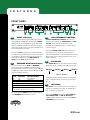
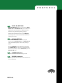
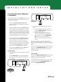
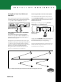
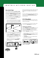
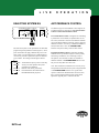
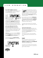
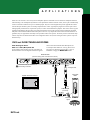
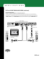
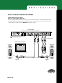
A Loudspeaker With Intelligence
User’s Guide
Introducing The Next Generation of Installed Sound
EVOi.net
C O N T E N T S
Safety Information . . . . . . . . . . . . . . . . . . . . .
1
Introduction . . . . . . . . . . . . . . . . . . . . . . . . . .
2
Design Overview . . . . . . . . . . . . . . . . . . . . . .
3
Features
EVOi.net Front
...............................
EVOi.net Rear . . . . . . . . . . . . . . . . . . . . . . . . . . . . . . . . . . .
4
6
Installation / Setup. . . . . . . . . . . . . . . . . . . . . .
7
Measurement Microphone . . . . . . . . . . . . . . . . . . . . . . . .
Starting Up . . . . . . . . . . . . . . . . . . . . . . . . . . . . . . . . . . . . .
Testing the System . . . . . . . . . . . . . . . . . . . . . . . . . . . . . .
Auto EQ . . . . . . . . . . . . . . . . . . . . . . . . . . . . . . . . . . . . . . .
Delay Setting . . . . . . . . . . . . . . . . . . . . . . . . . . . . . . . . . . .
8
9
10
11
14
Live Operation
Selecting System EQ . . . . . . . . . . . . . . . . . . . . . . . . . . . . .
Applications
..............................
Rectangular Rooms . . . . . . . . . . . . . . . . . . . . . . . . . . . . . .
Fan Shaped Rooms . . . . . . . . . . . . . . . . . . . . . . . . . . . . . .
15
17
17
22
Appendix . . . . . . . . . . . . . . . . . . . . . . . . . . . . . 25
Troubleshooting . . . . . . . . . . . . . . . . . . . . . . . 26
Technical Data . . . . . . . . . . . . . . . . . . . . . . . . 28
Warranty . . . . . . . . . . . . . . . . . . . . . . . . . . . . . 29
©2001 JBL Professional
IMPORTANT SAFETY INFORMATION - READ THIS CAREFULLY
This equipment has been tested and found to comply with the following European and international standards for Electromagnetic Compatibility and Electrical Safety:
Radiated Emmissions (EU): EN55022B (1992)
RF Immunity (EU): IEC801-3 (1994)
Electrostatic Discharge(EU): IEC801-2 (1984)
Fast Transients(EU): IEC801-4 (1988)
Electrical Safety (EU): EN60065 (1994)
Electrical Safety(USA): UL6500/ETL (1996)
Electrical Safety(CAN): CAN/CSA-E65/ETLc (1996)
Before using the apparatus read these instructions, follow all instructions, heed them and keep in a
safe place.
Clean only with a damp cloth. Do not block any of the ventilation openings. Install in accordance with the manufacturer’s
instructions.
Do not defeat the safety purpose of the grounding type plug. A grounding plug has two blades and a third grounding prong. The
third prong is provided for your safety. When the provided plug does not fit into your outlet, consult an electrician for replacement of the obsolete outlet.
Protect the power cord from being walked on or pinched particularly at plugs, convenience recepticals and the point where they
exit from the apparatus.
Only use attachments/accessories specified by the manufacturer.
Unplug this apparatus during lightning storms or when not in use for a long time.
WARNING – TO REDUCE THE RISK OF FIRE OR SHOCK, DO NOT EXPOSE THIS APPARATUS TO RAIN OR
MOISTURE.
DO NOT REMOVE COVERS, NO USER SERVICABLE PARTS INSIDE, REFER SERVICING TO QUALIFIED
SERVICE PERSONNEL.
THIS EQUIPMENT MUST BE GROUNDED.
!
CAUTION
ATTENTION
RISK OF ELECTRONIC SHOCK
DO NOT OPEN
RISQUE DE CHOC ELECTRIQUE
NE PAS ENLEVER
DO NOT EXPOSE
TO RAIN OR MOISTURE
NE PAS EXPOSER A
LA PLUIE NI L'HUMIDITE
IT SHOULD NOT BE NECESSARY TO REMOVE ANY PROTECTIVE GROUND OR SIGNAL CABLE SHIELD
CONNECTIONS TO PREVENT GROUND LOOPS. ANY SUCH DISCONNECTIONS ARE OUTSIDE THE
RECOMMENDED PRACTICE OF JBL PROFESSIONAL AND WILL RENDER ANY EMC OR SAFETY
CERTIFICATION VOID.
For continued compliance with international EMC legislation ensure that all input and output cables are wired with the cable
screen connected to Pin 1 of the XLR connectors. The input XLR Pin 1 is connected to the chassis via a low value capacitor,
providing high immunity from ground loops while ensuring good EMC performance.
1
EVOi.net
I N T R O D U C T I O N
WELCOME
Thank you for purchasing an EVOi.net Speaker System
Controller or, if you have been referred to this section via
EVOi.sys, thank you for purchasing an EVOi.sys. As part
of EVO Systems, the EVOi.net provides simple to
understand yet flexible access to the full functionality of
EVO Intelligent Loudspeaker Systems. We like to say the
EVOi.net accesses the intelligence.
PACKAGE CONTENTS
Upon unpacking the EVOi.net please take note of the
contents as listed below. If you do not have the contents
listed then please contact your dealer as soon as possible.
EVOi.net Contents:
1 x EVOi.net
1 x AC Power Cord
1 x JBL Measurement Microphone with clip and case
1 x 100’ XLR Balanced Signal Microphone Cable
1 x EVO User’s Guide
2
EVOi.net
D E S I G N
O V E R V I E W
The EVOi.net is either supplied in a 19” rack mount
configuration or as part of the EVOi.sys.
Simplicity in the presentation is at the forefront of the
EVOi.net design. For installed loudspeaker systems, it is
not practical to initiate setup and operational function with
control on the actual loudspeakers. Therefore the EVOi.net
simply provides a more convenient remote control of the
functions in the EVO Intelligent Loudspeaker Systems.
The control is presented in two sections: one for installation
and setup; the other for operation. The functions are
initiated with simple button pushes and responses annunciated with colored indicators (LEDs). The hook-up is
enabled with standard signal cable and XLR connectors.
Due to the nature of the technology, no other network
cables are required to communicate button pushes to the
EVO Loudspeakers.
3
EVOi.net
F E A T U R E S
FRONT PANEL
Figure 1
1
1
2
3
INPUT Indicators
Two sets of LED indicators monitor audio signal levels at
the inputs A (left) and B (right). When the green SIGNAL
indicators are on, the input signals are greater than -40 dB.
Below this threshold, the indicators will be off, signifying
that the input signals are too low for proper amplification or
are disconnected from the system.
When the red CLIP indicators are on, audio signal levels
are 2 dB below the maximum clip level. If the input signals
exceed this level, distortion will result. When you observe
this condition, simply lower the L MIX R (Master)
Faders until the CLIP indicators turn off.
4
5
3
SPEAKER STATUS Indicators
Two sets of LED indicators, OKAY and WARNING,
provide visual status of amplified signal levels driving
EVO loudspeakers connected to the main outputs, 1A (left)
and 2B (right), and the auxiliary outputs, 3A (left) and 4B
(right). The indicator states are:
7
8
9
ANTI FEEDBACK CONTROL
The ANTI FEEDBACK CONTROL (AFC) section
consists of two mode buttons, FIXED SETUP and LIVE
AFC ON, and associated LED indicators for state
confirmation. For detailed operation, see Anti Feedback
Control on page 15.
The LEDs, FILTERS FREE (4, 2, and 1), indicate the
least number of live or fixed AFC filters available to
connected loudspeakers for a selected mode.When no spare
filters remain on one or more loudspeaker circuits, the 1
indicator will flash.
4
2
6
EQ SELECT
Press EQ SELECT one or more times to select a desired
equalization setting, according to the following sequence:
NEUTRAL
SPEECH
MUSIC 1
MUSIC 2
Figure 2 - EQ Select
OKAY
Off
On
On
On/Off1
Flashing2
WARNING
Off
Off
On (flickering)
Off
On (always)
SPEAKER STATUS
Not connected
Connected
Connected, Output Clipping
Test Mode, Pink Noise1
Error2
1. See “Testing The System” on page 10
2. See “Speaker Status Error Codes” on page 26
For easy recognition, OKAY indicators will turn on green,
while WARNING indicators will turn on red.
An associated LED will light to indicate the current selection. For detailed operation, see Selecting System EQ on
page 15.
5
SETTINGS
Press TEST to start the audio test mode. An orange LED
will turn on, confirming your choice. For detailed operation, see Starting Up on page 10.
The orange LOCKED LED indicates TEST, AEQ ON,
AUTO EQ SETTING, and DELAY SETTING are
disabled and their parameters are locked via the LOCKOUT SWITCH (on the rear panel).
4
EVOi.net
F E A T U R E S
6
AUTO EQ SETTING
AUTO EQ SETTING includes two setup buttons, MAIN
SETUP 1&2 and AUX SETUP 3&4, and associated LED
indicators for state confirmation. For detailed operation,
refer to See Using The Auto EQ Setting on page 11.
After the Auto EQ filters have been set, use AEQ ON to
turn Auto EQ on or off. An associated LED indicator will
confirm your selection.
7
DELAY SETTING
Press DELAY SETTING to initiate delay setup on
auxiliary outputs, AUX OUT 3A (left) and AUX OUT 4B
(right). For detailed operation, refer to Delay Setting on
page 14.
The orange SETUP LED will flash during setup and the
green DELAY SET LED will turn on once the delay time
has been set on auxiliary outputs, AUX OUT 3A (left) and
AUX OUT 4B (right).
8
POWER Indicator
A green LED indicates EVOi.net is being powered.
9
RS232 Connector
Use this 8-pin mini DIN connector to connect the EVOi.net
to a PC’s RS232 port.
5
EVOi.net
F E A T U R E S
REAR PANEL
Figure 3
10
10
11
12
13
14
15
RU Mounting Holes
The EVOi.net is equipped with four mounting holes for
installation in one RU (rack unit) space.
11
16
15
17
18
10
OUTPUTS (4B/3A), Auxiliary
Two 3-pin male XLR connectors for right (4B) and left
(3A) connection to auxiliary EVOi.324 loudspeakers using
a pair of XLR signal cables.
Power Connector
Insert the enclosed power cord into the IEC connector to
supply the specified AC power.
12
For mono operation, press MONO SUM to sum the input
signals and route the combination to both outputs. The
mono signal level will be 4 dB lower than the stereo level.
Fuse
The removable fuse protects internal circuits. When
replacing the fuse, be sure to use the same type as specified.
13
16
OUTPUTS (2B/1A), Main
Two 3-pin male XLR connectors for right (2B) and left
(1A) connection to main EVOi.324 loudspeakers using a
pair of XLR signal cables.
INTERFACE Connectors
Two 8-pin RJ-45/Shellnet connectors, labeled LINK IN and
LINK OUT, will provide interlinking to other EVOi.net
units. Functionality will be determined at a later date.
For mono operation, press MONO SUM to sum the input
signals and route the combination to both outputs. The
mono signal level will be 4 dB lower than the stereo level.
14
17
Lockout Switch
To protect settings from being inadvertently changed, press
this recessed button once to disable TEST, AUTO EQ
SETTING, AEQ ON, and DELAY SET and to lock their
parameters. The orange LOCKED LED (under SETTINGS on the front panel) will turn on to confirm the
lockout. To restore functionality and to change settings,
press this recessed button once again.
INPUTS (B/A)
Two 3-pin female XLR connectors for right (B) and left (A)
connection to the EVOi.sys R MIX OUTPUTS L using a
pair of XLR signal cables.
18
SETUP MIC
A 3-pin female XLR connector for connection to the
enclosed measurement microphone using the supplied 100’
XLR signal cable.
6
EVOi.net
I N S T A L L A T I O N S / S E T U P
STARTING UP
Connecting The System
Installation Notes
Although installing an EVOi.net is straightforward, please
review the following notes to achieve the best installation:
•
Choose a mounting location that provides direct front
panel viewing and easy access to the controls.
•
The EVOi.net does not have a power on/off switch and
therefore is “ON” whenever AC power is activated. If
desired, use switched power outlets for master system
control.
•
We strongly recommend the use of high-quality,
shielded audio cables for connection to the mixer and
EVO loudspeakers.
EVOi.324
Rear
Use Figure 4 (below) as an aid for interconnecting
EVOi.net to up to four EVOi.324 loudspeakers and your
mixer.
For help with loudspeaker placement, refer to EVOi.324 –
Applications on page 7 of the EVOi.324 Users Guide.
Using Mono Sum
If your application calls for mono sound, simply press
MONO SUM on the rear of the EVOi.net. This will sum
the pair of outputs. (See EVOi.net – Features 15 and 16 on
page 6).
NOTE: Activating MONO SUM will lower the output level
by 4 dB.
Output on
Generic Mixer
EVOi.net
Rear
EVOi.sys
Rear
Input
OR
XLR Signal Cable
Figure 4 - Basic System Connections
7
EVOi.net
I N S T A L L A T I O N S / S E T U P
STARTING UP
Connecting Measurement
Microphone
IMPORTANT: EVOi.net is supplied with a dedicated JBL
Measurement Microphone and 100’ XLR - XLR balanced
signal cable. Successful setup will ONLY occur if the JBL
Measurement Microphone is used. When not in use please
keep it in a safe place for future use.
Use the supplied 100’ XLR signal cable to hookup the
Measurement Microphone, as shown in Figure 5 below.
JBL Measurement Microphone
Figure 6 - The JBL Measurement Microphone with
adapter, 100’ XLR cable and protective case are included
with the EVOi.net Controller and EVOi.sys System.
100’ XLR Cable (Included)
EVOi.net
Rear
Figure 5 - Measurement Microphone Hook Up
Figure 7- As your measurement microphone is a precise
audio tool, please keep it in its protective case when not
in use.
8
EVOi.net
I N S T A L L A T I O N S / S E T U P
STARTING UP
INPUT
evo
SPEAKER STATUS
WARNING
ANTI FEEDBACK CONTROL
FIXED AFC SET
FILTERS FREE 1
2
Initial Settings and Powering Up
3
EVOi.net
SIGNA
AL
FIXED SETUP
LIVE AFC ON
OKAY
SPEAKER SYSTEM CONTROLLER
Upon activation, all of the LEDs on the
A B
1 2
3 4
front panel should light up once and then
go out. Depending upon whether or not
Figure 8
EVOi.net has been powered up before or
Pushing the Buttons
has just been shipped from the factory, the following
The soft buttons on EVOi.net have been designed such that
indicators will remain on:
it is very difficult to accidentally activate or switch
HOLD TO CLEAR FIXED
Factory Settings
After shipping from Factory the power up defaults will be
as follows…
Settings
Delay Setup
AEQ On
Aux Auto EQ Setup
Main Auto EQ Setup
Test
EQ Select
Live AFC
Fixed AFC
Power Up State
Off
Off
Off
Off
Off
Neutral
Off
Off
Normal Power Up Settings
After first use the power up defaults will be as follows…
Settings
Delay Setup
AEQ On
Aux Auto EQ Setup
Main Auto EQ Setup
Test
EQ Select
Live AFC
Fixed AFC
Power Up State
Last Known Setting
Last Known Setting
Last Known Setting
Last Known Setting
Off
Last Known Setting
Last Known Setting
Last Known Setting
HOLD TO CLEAR LIVE
something off. To avoid frustration please refer to the
following guideline for button operation:
Press, or Press-and-release means to Press the button and
release it within 1 second.
Press-and-hold means to Press a key and hold it for at
least 2 seconds.
Understanding Speaker Status
On the front panel, two sets of LED indicators (see
Features on page 4) provide visual status of amplified
signal levels driving EVO loudspeakers. The indicator
states are:
OKAY
Off
On
On
On/Off1
Flashing2
WARNING
Off
Off
On (flickering)
Off
On (always)
SPEAKER STATUS
Not connected
Connected
Connected, Output Clipping
Test Mode, Pink Noise1
Error2
1. See “Testing The System” on page 10.
2. See “Speaker Status Error Codes” on page 26.
For easy recognition during the “On” state, OKAY indicators
are green, while WARNING indicators are red.
If upon activation the WARNING indictor/s illuminate (SPEAKER STATUS), the green OKAY
LED will flash an error code. This is a Speaker
Status Error Code – see Troubleshooting on page
26 and refer to AC Power Up on page 25.
9
EVOi.net
I N S T A L L A T I O N S / S E T U P
STARTING UP (continued)
Testing the System
At the beginning of or anytime during a system setup, the
hookup configuration of the EVO loudspeaker can be tested
by using the TEST button.
EQ SELECT
MUSIC I
MUSIC II
SPEECH
NEUTRAL
SETTINGS
LOCKED
TEST
AUTO EQ SETTING
EQ SET
MAIN OUT
SETUP 1&2
HOLD TO CLEAR MAIN
This button is used to control the user audio test mode, i.e.
pressing it will produce ‘pink noise’ output from each EVO
loudspeaker.
EQ SET
AUX OUT
SETUP 3&4
AEQ ON
HOLD TO CLEAR MAIN
Figure 9
The first press of the TEST button will…
1. Enable the Test Mode.
2. Illuminate the orange TEST LED.
3. Cause the first found EVO loudspeaker to transmit
‘Pink Noise’.
If the LOCK switch is engaged at any time during Test
Mode, Test Mode will immediately end. The TEST
indicator LED will be extinguished and any EVO loudspeakers will stop transmitting ‘Pink Noise’.
4. Flash the relevant Speaker Status Green OKAY LED to
indicate the Limpet transmitting.
Successive presses of the TEST button will…
1. Move the ‘Pink Noise’ to the next EVO loudspeaker.
2. Indicate the ‘New Transmitting’ EVO loudspeaker by
flashing the relevant Speaker Status Green OKAY
LED.
When all attached EVO loudspeakers have been tested, the
next press of the TEST button will exit Test Mode and
extinguish the TEST LED. There is a short delay between
pressing the TEST button for the last time and returning all
speakers to normal operation.
10
EVOi.net
I N S T A L L A T I O N S / S E T U P
USING THE AUTO EQ SETTING
Placing Measurement Microphone
for MAIN EVO Loudspeakers
For simple applications of up to two EVO loudspeakers
hooked up to OUTPUTS 1A and 2B (the MAIN OUT
outputs), optimum placement of the Measurement Microphone is illustrated in Figure 10.
The placement follows a simple height-to-depth ratio of
1:2. For a given loudspeaker height the optimum position is
a distance twice the height away from it, into the listener
area. For instance, if the speaker is 10’ in the air, measure
20’ into the listening area and place the microphone there.
It is very important that the Measurement Microphone
remains on the central axis of the room or listener area,
equidistant from each loudspeaker. See Figures 11 a, b, c.
A rough rule of thumb is that the Measurement Microphone
should remain equidistant from both loudspeakers at a point
approximately 2/3rd the length of the listener area away
from the loudspeakers.
3X
2X
1X
Figure 10 - Typical Measurement Microphone Placement
Figure 11a - Placement for Single Speaker
For optimum result please also make note of the type of
floor in the listening area and follow the guide below in
Figures 12a and 12b.
Soft surfaces - Measurement Mic
on a stand at least 6’ high.
Figure 11b - Placement for Stereo Pair
Figure 12a - Soft Surfaces (carpet, fabric)
Hard surfaces - Measurement
Mic should be laid on the floor.
Figure 11c - Placement for Mono Array
Figure 12b - Hard Surfaces (like Gymnasiums)
11
EVOi.net
I N S T A L L A T I O N S / S E T U P
Performing Auto EQ for MAIN OUT
Loudspeakers
SETTINGS
LOCKED
TEST
Before starting, check that the LOCKED indicator is off. If
it is on, then use the rear panel switch (Feature 14 page 6)
to enable Auto EQ buttons.
AUTO EQ SETTING
EQ SET
MAIN OUT
SETUP 1&2
HOLD TO CLEAR MAIN
EQ SET
AUX OUT
SETUP 3&4
AEQ ON
HOLD TO CLEAR MAIN
Figure 13 - Main Out
Setup Button
1. Press the round MAIN OUT SETUP 1&2 button
(Figure 13). On release, the LED flashes, and the Auto
EQ routine begins.
2. The EVO loudspeaker connected to MAIN OUTPUT
1A is instructed to Auto EQ and generates its own test
signal. This lasts for a few seconds. It is recommended
that during the test signal, background noise is kept to a
minimum. It takes about 40 seconds after the test signal
for the EVO loudspeaker’s built-in computer to adjust
and acoustically optimize itself to its environment.
3. Once set, an instruction is automatically sent to the
EVO loudspeaker connected to MAIN OUTPUT 2B.
If an EVO loudspeaker is connected, then it also
performs its own Auto EQ routine. If an EVO loudspeaker is not connected or when the EVO loudspeaker
connected to MAIN OUTPUT 2B has completed its
Auto EQ routine, the EQ SET indicator will light.
4. At the same instant EQ SET lights up, AEQ ON also
illuminates indicating that Auto EQ is on.
Testing Auto EQ
1. Pass program signal to EVOi.net and listen to the result
of Auto EQ.
2. Press the AUTO EQ button (the LED will illuminate
when Auto EQ is active) and listen to the ‘Before &
After’ Auto EQ.
SETTINGS
LOCKED
TEST
AUTO EQ SETTING
EQ SET
MAIN OUT
SETUP 1&2
HOLD TO CLEAR MAIN
EQ SET
AUX OUT
SETUP 3&4
AEQ ON
3. If the result of Auto EQ is desirable then continue, if
not then:
i. Check the position and aim of the EVO loudspeakers, CLEAR AUTO EQ (see below) and
repeat the Auto EQ routine.
ii. The Measurement Microphone may not be
located in a position that strongly reflects the
natural acoustics of the room. CLEAR AUTO
EQ (see below), move the Measurement
Microphone a few feet and repeat the Auto EQ
routine.
Pressing any button during the Auto EQ routine will
abort the process and settings will return to their previous
values.
If an error is detected during the Auto EQ routine, this will
be shown on the SPEAKER STATUS indicators and an
attempt will be made to restore any Auto EQ settings to
their previous values.
Clear Auto EQ
Press the round MAIN OUT SETUP 1&2 button again and
the Auto EQ routine will run again. Previous Auto EQ
settings do not have to be cleared first.
Press-and-hold this button and all of the previous Auto EQ
settings will clear and the EQ SET INDICATOR will go
out as will the AEQ ON INDICATOR.
HOLD TO CLEAR MAIN
Figure 14 - The Auto EQ Button
12
EVOi.net
I N S T A L L A T I O N S / S E T U P
Using More Than Two EVO Loudspeakers
If your system consists of more than two EVO loudspeakers then these auxiliary/delay systems should be hooked up
to outputs 3A and 4B, the AUX OUT Loudspeakers.
LINK IN
MONO
SUM
4B
MONO
SUM
3A
2B
Once the Measurement Microphone has been positioned
and the SETTINGS LOCKED function has been disabled,
running the Auto EQ routine is exactly the same as for the
MAIN OUT SETUP 1&2.
Follow steps 1 – 4 from page 12, pressing AUX OUT
SETUP 3&4 instead of MAIN OUT 1&2.
FLOATING BALANCED OUTPUTS
INTERFACE
LINK OUT
Performing Auto EQ for AUX OUT Loudspeakers
1A
Figure 15 - AUX Out
Speakers 3A and 4B
SETTINGS
LOCKED
TEST
AUTO EQ SETTING
EQ SET
MAIN OUT
SETUP 1&2
HOLD TO CLEAR MAIN
Placing Measurement Microphone for AUX EVO
Loudspeakers
For applications of more than two EVO loudspeakers
hooked up to outputs 3A and 4B(the AUX OUT outputs),
optimum placement of the Measurement Microphone is
illustrated below in Figure 16.
Ideal placement of the Measurement Microphone is again
determined by following the simple height-to-depth ratio of
1:2, where, for a given loudspeaker height the optimum
position is a distance twice the height away from it, into the
listener area. It is still crucial that the Measurement
Microphone remains on the central axis of the room or
listener area, equidistant from each loudspeaker.
EQ SET
AUX OUT
SETUP 3&4
AEQ ON
HOLD TO CLEAR MAIN
Figure 17 - AUX Out
Auto EQ Setup
At step 4, once the AEQ ON indicator has illuminated, the
Auto EQ for all connected EVO Loudspeakers can be
listened to simultaneously. See Testing Auto EQ.
If, as the result of this listening test, the Auto EQ set is not
desirable, then the settings can be cleared. See Clear Auto
EQ, and Auto EQ can be repeated.
Figure 16 - Measurement Microphone Placement for Auto EQ of Aux Speakers 3A and 4B
13
EVOi.net
I N S T A L L A T I O N S / S E T U P
DELAY SETTING
EVO Loudspeakers hooked up to AUX OUT 3A & 4B
outputs can be instructed to automatically set their correct
delay and level to perform optimally with EVO Loudspeakers hooked up to MAIN OUT 1A & 2B outputs. A Haas
delay will also be added to the AUX OUT Loudspeakers to
make sure the MAIN OUT Loudspeakers are the acoustic
focus. Before starting, check that the LOCKED indicator is
off. If it is on, then use the rear panel switch (Feature 14,
page 6) to enable the DELAY SET button.
1. Position the Measurement Microphone in the optimum
position. This is located equidistant from each AUX
(delay) EVO Loudspeaker (in most cases on the central
axis of the listening area), approximately 10 feet away.
10'
Pressing any button during the Delay Setting routine will
abort the process and settings will return to previous
values.
If an error is detected during the Delay Setting routine, this
will be shown on the SPEAKER STATUS indicators, and
an attempt will be made to restore any Delay settings to
their previous values.
Clear Delay Setting
Press the round DELAY SET button again and the Delay
Setting routine will run again. Previous Delay Settings do
not have to be cleared first.
Press-and-hold this button and all previous Delay settings
will clear and the DELAY SET indicator will go out.
Locking the Settings
After each SETTING routine, the LOCKED indicator will
flash once to remind you that this setting can be locked.
Once the desired SETTINGS routines have been performed and all are satisfactory, they can be “locked in” as
the default or NEUTRAL system settings.
Figure 18: Measurement Mic Placement for Setting Delay
2. Press the round delay SETUP button. When the button
is released the SETUP indicator flashes and the EVO
Loudspeakers hooked up to the MAIN OUT outputs
emit a test signal. Then the EVO Loudspeakers hooked
up to the AUX OUT outputs emit a test signal.
3. When the correct delay and level for the AUX EVO
Loudspeaker/s have been set the DELAY SET
indicator illuminates.
AUTO EQ SETTING
DELAY SETTING
1. On the rear panel, use a pin or matchstick to engage the
LOCKOUT SWITCH (Feature 14, page 6).
2. Once engaged, the LOCKED indicator will illuminate
continuously.
3. All SETTING buttons will now be disabled until the
Lockout Switch is disengaged.
FLOATING BALAN
INTERFACE
LINK OUT
LINK IN
MONO
SUM
POWER
4B
EQ SET
MAIN OUT
SETUP 1&2
EQ SET
AUX OUT
SETUP 3&4
3A
DELAY SET
AEQ ON
SETUP
Figure 20: Lockout Switch
HOLD TO CLEAR MAIN
HOLD TO CLEAR MAIN
HOLD TO CLEAR DELAY
RS-232
Figure 19: Delay Setup Button
14
EVOi.net
L I V E
ANTI FEEDBACK CONTROL
SELECTING SYSTEM EQ
ANTI FEEDBACK CONTROL EQ SELECT
FIXED AFC SET
FIXED SETUP
HOLD TO CLEAR FIXED
FILTERS FREE 1
2
3
LIVE AFC ON
MUSIC I
MUSIC II
SPEECH
NEUTRAL
O P E R A T I O N
SETTINGS
LOCKED
TEST
HOLD TO CLEAR LIVE
Figure 21: EQ Select Button
The total EVO System can be optimized for an individual
program using the EQ SELECT button (Figure 21). Each
press of the button will apply a different EQ curve to the
entire system, very much like the way a domestic HiFi or
car stereo EQ is used to optimize the system for different
types of music. The settings scroll through as follows:
NEUTRAL The default start-up EQ or last set Auto EQ.
SPEECH
An EQ curve that optimizes the system
performance for SPEECH.
MUSIC I
Ideal for LIVE music performance.
MUSIC II
Recommended for the enhancement of
RECORDED MUSIC playback.
Two different types of Anti Feedback Control engines can
be initiated and set up via EVOi.net: Live Anti Feedback
Control and Fixed Anti Feedback Control.
Live Anti Feedback Control is designed to be used during
a performance. Once initiated, six dynamic filters are set
into action, instructed to search for and eliminate feedback
once found. When feedback is detected, a filter is placed to
eliminate it before it “runs away”. If additional feedback is
found, another filter is used. The FILTERS FREE
indicators tell you how many of the six filters are left.
Fixed Anti Feedback Control is designed to eliminate
feedback before a performance begins, a routine possibly
done during a soundcheck. For a fixed stage setup of
microphones, once initiated, six filters are available to
eliminate feedback. The FILTERS FREE indicators also
tell you how many filters have been used.
Note: There should be no feedback with a correctly set up
and operated sound reinforcement system. The general idea
of the FILTERS FREE indicators is as a guide to the
operator. If all the Anti Feedback Filters have been used,
this is a strong indication that the whole system needs
adjustment. Typically this is confined to the mix.
15
EVOi.net
L I V E
O P E R A T I O N
Live Anti Feedback Control
Initiate Live Anti Feedback Control by pressing the square
button. LIVE AFC ON will illuminate. As feedback is
found, filters will be used to eliminate it.
SPEAKER STATUS
ANTI FEEDBACK CONTROL EQ SELECT
Once all the
available
1 2
3 4
filters have
been used, as indicated by FILTERS
Figure 23 - Live
Anti Feedback
FREE 1 illuminating in RED, the
On/Off
Live Anti Feedback engine will
continue to eliminate feedback, reassigning the oldest or
first placed filter to the newest feedback frequency. This
will continue, but the RED LED indicates that there is a
problem with the performance mix that really should be
addressed, by either identifying the problem microphone
and reducing its individual channel fader or by reducing the
overall level, bringing down the master faders.
FIXED AFC SET
WARNING
FIXED SETUP
OKAY
FILTERS FREE 1
2
3
LIVE AFC ON
HOLD TO CLEAR FIXED
MUSIC I
MUSIC II
SPEECH
NEUTRAL
Now very slowly push the master faders up on the mixer
(the slower the action, the more accurate the detection and
allocation of filters will be). If feedback occurs, each EVO
Loudspeaker will eliminate it. As you continue to push the
faders up more feedback may occur at other frequencies,
and you will see that the FILTERS FREE indicators show
more filters being used.
HOLD TO CLEAR LIVE
When all the filters have been used, the FIXED SETUP
indicator will stop flashing. You can quit the FIXED AFC
setup at any time by pressing any button as long as all of
the available filters have not been used. The FIXED AFC
SET indicator will illuminate and Fixed Anti Feedback
Control has been set and is ready to go.
It is advisable to keep extraneous noises to a minimum
during this procedure to prevent inappropriate allocation of
filters.
Fixed Anti Feedback Control
Set up the performance system on stage for normal
operation, for example, by placing all microphones in their
typical positions and faders on the mixing desk set to that
of a typical mix. Set the master faders initially in their
minimum settings.
Clearing Anti Feedback Filters
Both sets of Live and Fixed Anti Feedback filters can be
cleared by pressing and holding their respective buttons. As
you hold the button each allocated filter is removed
sequentially. The FILTERS FREE indicators will show
filters being removed.
FIXED AFC setup can only be performed if LIVE AFC is
off. If the LIVE AFC indicator on EVOi.net is on, press
and hold the LIVE AFC button until the filter indicators
and the LIVE AFC indicators are extinguished.
If during this process a filter is removed and feedback
occurs, releasing the button will instantaneously re-insert
the filter.
Now press-and-hold the round FIXED AFC SETUP
button until the FIXED SETUP indicator starts flashing.
PANIC
SPEAKER STATUS
FIXED SETUP
OKAY
1 2
ANTI FEEDBACK CONTROL EQ SELECT
FIXED AFC SET
WARNING
3 4
Figure 24 Fixed Anti
Feedback On/Off
HOLD TO CLEAR FIXED
FILTERS FREE 1
2
3
LIVE AFC ON
MUSIC I
MUSIC II
SPEECH
NEUTRAL
If you run into problems with any portion of the system
setup and operation, it is possible to reset all EVO
loudspeaker settings by pressing all square LIVE AFC ON,
EQ SELECT and AEQ ON buttons simultaneously. This
will restore the factory default settings.
HOLD TO CLEAR LIVE
It is possible to reset the settings in the EVO loudspeakers
using data stored in EVOi.net, see Power Up Operation on
page 9 for further information.
16
EVOi.net
A P P L I C A T I O N S
EVOi.net is the “network” center of any EVO Loudspeaker System. It facilitates access to all EVO Loudspeaker functions
and monitoring. EVO Loudspeaker Systems have been optimized for small to mid-size venues, where a pair will sufficiently
reinforce sound for an audience of up to five hundred people. They have been designed with specific applications in mind:
schools and sports facilities; places of worship; and performance venues. Typically the program of events are quite varied
and high quality reinforcement is required for speech, live music and recorded music playback. This section refers to typical
applications identified in the EVOi.324 Users Guide and describes how to hook up EVOi.net and optimize the placement
and position of the dedicated Measurement Microphone. These are very simple instructions and are for ideal situations. As
guidelines, they are approximate and it may not be possible to follow strict practice. The beauty of EVO is that all the setup
routines only take a few moments and that if one configuration doesn’t work, then re-setting the entire system is only a few
moments away!
EVOi.net IN RECTANGULAR ROOMS
Small Rectangular Room:
EVOi.net + 1 Main (Mono) EVOi.324
For the simplest EVO System, EVOi.net is hooked up as
illustrated below. The inset diagram indicates the approxi-
mate location of the Measurement Microphone (for
accurate placement details see ‘Placing Measurement
Microphone for MAIN EVO Loudspeakers’ page11).
Remember to engage the MONO SUM switch!
EVOi.net Rear
(NOTE: For clarity, power connections are not shown.)
IMPORTANT: Make sure POWER is off
before making connections.
Mono
Mono
In
XLR Signal Cable
EVOi.324
Main
Speaker Placement In Room
1
Mono
Approximate measurement microphone placement.
Audio Output
1 = Auto EQ. Main Out Setup 1&2
(from Mixer)
Main Mono
XLR Signal Cable
EVOi.324
Input
17
EVOi.net
A P P L I C A T I O N S
EVOi.net IN RECTANGULAR ROOMS (continued)
Longer Rectangular Room:
EVOi.net + 1 Main (Mono) EVOi.324 + 1 Delay (Mono) EVOi.324
In a longer rectangular room, additional coverage may be required. Page 12 of the EVOi.324 Users Guide illustrates a
typical application. The diagram below illustrates the hook-up required and typical Measurement Microphone placement,
see details page 12 . The inset diagram also show the order of Measurement Microphone placements when setting Auto EQ
on MAIN and AUX (Delay), also DELAY SETUP Microphone position. Remember to engage the MONO SUM switch.
EVOi.net Rear
(NOTE: For clarity, power connections are not shown.)
IMPORTANT: Make sure POWER is off
before making connections.
Mono
Mono
In
Mono
In
XLR Signal Cable
Speaker Placement In Room
EVOi.324
Delay
2
3
EVOi.324
Main
1
Approximate measurement microphone placement.
1 = Auto EQ. Main Out Setup 1A
2 = Auto EQ. Aux Out Setup 3A
3 = Delay Setup
Mono
Audio Output
(from Mixer)
Main Mono
Delay Mono
XLR Signal Cables
EVOi.324
Input
EVOi.324
Input
18
EVOi.net
A P P L I C A T I O N S
EVOi.net IN RECTANGULAR ROOMS
Smaller/Wider Rectangular Room:
EVOi.net + 2 Main (Stereo) EVOi.324s
The hook up diagram below illustrates the most typical EVO Systems configuration. The inset diagram illustrates the
approximate Measurement Microphone position when performing Auto EQ setup (for accurate placement details see
‘Placing Measurement Microphone for MAIN EVO Loudspeakers’ page11).
EVOi.net Rear
(NOTE: For clarity, power connections are not shown.)
IMPORTANT: Make sure POWER is off
before making connections.
R
L
R
L
Out
XLR Signal Cables
Speaker Placement In Room
EVOi.324
Main R
EVOi.324
Main L
1
R
Approximate measurement microphone placement.
1 = Auto EQ. Main Out Setup 1&2
L
Audio Outputs
(from Mixer)
Main R
Main L
XLR Signal Cables
EVOi.324
Input
EVOi.324
Input
19
EVOi.net
A P P L I C A T I O N S
EVOi.net IN RECTANGULAR ROOMS (continued)
Longer / Wider Rectangular Room:
EVOi.net + 2 Main (Stereo) EVOi.324s + 2 Delay (Stereo) EVOi.324s
In large rooms, an EVO system as illustrated in the inset diagram may be required. EVOi.324s are hooked up to MAIN
OUT 1&2 and the Delays, AUX OUT 3&4. Stereo is required, so EVOi.324s are positioned as shown (refer to EVOi.324
Users Guide page 13) and the Measurement Microphone placement and order of positioning is shown.
EVOi.net Rear
(NOTE: For clarity, power connections are not shown.)
IMPORTANT: Make sure POWER is off
before making connections.
R
L R
Out
L
R
L
Out
XLR Signal Cables
Speaker Placement In Room
EVOi.324
Main R
EVOi.324
Main L
2
3
1
Approximate measurement microphone placement.
1 = Auto EQ. Main Out Setup 1&2
2 = Auto EQ. Aux Out Setup 3&4
3 = Delay Setup
R
L
Audio Outputs
(from Mixer)
Main R
EVOi.324
Delay R
Main L
EVOi.324
Input
EVOi.324
Input
EVOi.324
Input
EVOi.324
Input
Delay R
EVOi.324
Delay L
Delay L
XLR Signal Cables
20
EVOi.net
A P P L I C A T I O N S
EVOi.net IN RECTANGULAR ROOMS
Longer / Wider Rectangular Room:
EVOi.net + 2 Main (Mono Array) EVOi.324s + 2 Delay (Mono Array) EVOi.324s
Another typical configuration for larger rooms is to configure two mono arrays, as illustrated in the inset diagram.
EVOi.net is hooked up as shown with both MONO SUM switches engaged.
EVOi.net Rear
(NOTE: For clarity, power connections are not shown.)
IMPORTANT: Make sure POWER is off
before making connections.
Mono
In
Mono
In
XLR Signal Cables
Speaker Placement In Room
EVOi.324
Delay Mono 1
EVOi.324
Main Mono 1
2
3
1
Approximate measurement microphone placement.
1 = Auto EQ. Main Out Setup 1&2
2 = Auto EQ. Aux Out Setup 3&4
3 = Delay Setup
Mono
Mono
Audio Outputs
(from Mixer)
Delay Mono 1
EVOi.324
Delay Mono 2
Main Mono 1
EVOi.324
Input
EVOi.324
Input
Delay Mono 2
EVOi.324
Input
EVOi.324
Main Mono 2
Main Mono 2
XLR Signal Cables
EVOi.324
Input
21
EVOi.net
A P P L I C A T I O N S
EVOi.net IN FAN-SHAPED ROOMS
Small Fan-Shaped Room:
EVOi.net + 1 Main (Mono) EVOi.324
EVOi.net hook up configuration and Measurement Microphone are as illustrated below. The setup is identical to EVOi.net
in a Small Rectangular Room.
EVOi.net Rear
(NOTE: For clarity, power connections are not shown.)
IMPORTANT: Make sure POWER is off
before making connections.
Mono
Mono
In
XLR Signal Cable
Speaker Placement In Room
1
Mono
Approximate measurement microphone placement.
Audio Output
1 = Auto EQ. Main Out Setup 1&2
(from Mixer)
Main Mono
XLR Signal Cable
EVOi.324
Input
22
EVOi.net
A P P L I C A T I O N S
EVOi.net IN FAN-SHAPED ROOMS
Medium Fan-Shaped Room:
EVOi.net + 2 Main (Mono Array) EVOi.324s
For a medium size Fan Shaped Room, broader coverage may be required, therefore the EVOi.324s are configured as
illustrated below (see EVOi.324 Users Guide, Applications page15). Hook up for this system is as illustrated below, also
approximate position of the Measurement Microphone (see ‘Placing Measurement Microphone for MAIN EVO Loudspeakers’ page11).
EVOi.net Rear
(NOTE: For clarity, power connections are not shown.)
IMPORTANT: Make sure POWER is off
before making connections.
Mono
In
XLR Signal Cable
Speaker Placement In Room
EVOi.324
Main Mono 1
1
Mono
Approximate measurement microphone placement.
Audio Output
1 = Auto EQ. Main Out Setup 1&2
(from Mixer)
Main Mono 1
EVOi.324
Input
EVOi.324
Main Mono 2
EVOi.324
Input
Main Mono 2
XLR Signal Cables
23
EVOi.net
A P P L I C A T I O N S
EVOi.net IN FAN-SHAPED ROOMS (continued)
Large Fan-Shaped Room:
EVOi.net + 2 Main (Mono Array) EVOi.324s + 2 Delay (Mono) EVOi.324s
For a Large Fan Shaped Room, the Main Array is set up and hooked up to EVOi.net as illustrated below. The Delay EVO
Loudspeakers are positioned as illustrated and hooked up to AUX OUT 3&4, providing additional coverage towards the
back of the listening area. The approximate positions and placement sequence of the Measurement Microphone are
illustrated on the inset diagram.
EVOi.net Rear
(NOTE: For clarity, power connections are not shown.)
IMPORTANT: Make sure POWER is off
before making connections.
R
Out
L
In
XLR Signal Cables
Speaker Placement In Room
EVOi.324
Delay L
EVOi.324
Main Mono 1
1
3
2
Approximate measurement microphone placement.
1 = Auto EQ. Main Out Setup 1&2
2 = Auto EQ. Aux Out Setup 3&4
3 = Delay Setup
R
L
Audio Outputs
(from Mixer)
Delay L
Main Mono 1
EVOi.324
Delay R
EVOi.324
Main Mono 2
EVOi.324
Input
EVOi.324
Input
Delay R
EVOi.324
Input
Main Mono 2
XLR Signal Cables
EVOi.324
Input
24
EVOi.net
A P P E N D I X
POWER UP OPERATION
There are two scenarios:
a) EVO Speakers have been changed/replaced or the
speakers hook up configuration is different.
b) EVOi.net has been changed/replaced.
Because of the difficulty in reliably determining which is
the appropriate scenario, the same procedure will be used in
both situations, and will allow the user to go back to the
alternative data set:
1. When powered up, the EVOi.net will download the
data from the speaker and compare the EVO loudspeaker data with the EVOi.net stored data. If the data
in the EVO loudspeakers does not match the data in the
EVOi.net, the SPEAKER STATUS indicators will
signify power-up disagreement error. Audio will not be
allowed to pass at this time.
2. The EVOi.net will backup the data that came from the
speakers to preserve it.
3. The EVOi.net will upload the original stored data into
the speakers.
4. If the user is happy with this, any button press will
clear the error, and unmute the system
5. To swap the data with the backed-up original speaker
data, the press MAIN OUT SETUP 1&2, AUX OUT
3&4, and DELAY SETUP simultaneously to download
the backed up EVO system data back into the EVO
loudspeakers. This will back-up the original EVOi.net
data, which the user can swap back to if required.
6. As a last resort the user may press the square LIVE
AFC ON, EQ SELECT, and AEQ ON buttons
simultaneously and restore the EVOi.324 settings to
their original factory defaults.
25
EVOi.net
T R O U B L E S H O O T I N G
EVOi.net is used as the interface for the set up and
operation of EVO Loudspeakers. The following section
may help in resolving some problems that may occur.
1. The front panel is inoperative and does not
respond to button pressing:
Check the LOCKED indicator. If it is illuminated, then
disengage the LOCKOUT Switch on the rear panel (#14
page 6).
2. The CLIP LED’s on the EVOi.net’s INPUT (#1
page 4) are illuminating:
The input signal level to EVOi.net is too high. Lower the
input level to EVOi.net. This is likely to occur if the EVO
Loudspeakers are not powered up and there is no audible
way of hearing a ‘clipped’ signal. If this is the case,
determine the cause of the EVOi.324’s not producing
sound.
After the error code is noted, the less serious errors may be
cleared by pressing any of the rectangular buttons on the
front panel of EVOi.net.
4. I’m sending signal, but one channel is not
working?
Check the configuration of MONO SUM (#15, 16 on page
6). MONO SUM engaged will allow signal from INPUT A
to flow to OUTPUTS 1 & 2 and 3 & 4 simultaneously.
With MONO SUM disengaged, signal from INPUT A will
flow to OUTPUTS 1 & 3 and signal from INPUT B will
flow to OUTPUTS 2 & 4.
5. My rear speakers aren’t working.
Has delay setup been engaged? (Is the DELAY SET LED
on above DELAY SETUP button)?
3. The SPEAKER STATUS indicators are flashing:
If only the RED LED is flashing occasionally, it indicates
that the electronics in the EVOi.324 connected to that
OUTPUT has detected a signal level that engages the builtin limiting circuitry. Lowering the signal level will resolve
this WARNING.
In a delay setup, typically the rear speakers are lowered to a
level (6-10dB) and delayed (approximately 15ms behind
any signal arriving from the main speakers) that allows
them to effectively disappear, forcing the localization of the
image to the front pair. Use the test function (if enabled) to
determine presence of all 4 speakers.
SPEAKER STATUS Error codes
Error codes are flashed as a sequence of two digits. After
the first digit, there is a short gap and after the second digit,
there is a longer (1 second) gap. Errors are prioritized, so if
a speaker has more than one error condition, the most
important error will be shown until it is cleared, at which
point the second error will be shown. Pressing any button
when an error code is being displayed will clear the highest
priority error.
6. Anti Feedback is on, yet my system is still
feeding back.
Has setup routine been used?
An error/status code is being reported when the green
(OKAY) LEDs begin flashing. Take note of the green
LED’s flashing code and its most likely cause using the
chart on page 27.
Have all filters been used? While the anti-feedback circuit
has been carefully designed to minimize the impact of
feedback, there will still be a point beyond which the
system is so feedback prone that further increase in gain
will result in additional feedback. A point is eventually
reached where so many feedback frequencies must be
removed, that it either requires an enormous number of
filters, or it requires lowering gain to keep the system
usable. The gain to the microphone should be lowered to
prevent the creation of feedback.
26
EVOi.net
T R O U B L E S H O O T I N G
Error Codes
1st Flash 2nd Flash
Digit
Digit
2
1
2
2
2
3
2
4
2
5
3
3
1
2
3
3
3
4
3
5
3
6
3
7
4
4
1
2
4
3
4
4
4
5
4
6
Meaning
Speaker Over Current. (Short Circuit on amplifier output). Contact Authorized Service
Representative.
Speaker Over Temperature. (Heatsink temperature too hot). Reduce level to allow speaker to
cool. Contact Authorized Service Representative if problem persists.
Speaker Under Current. (Open circuit on amplifier output). Contact Authorized Service
Representative.
Speaker Supply Voltage Error (either 3.3V or +/-15V). Contact Authorized Service Representative.
Speaker in Boot Loader Mode. Contact Authorized Service Representative
Error communicating with Speaker. Check connections between EVOi.net and EVOi.324.
Loudspeaker gone off-line during a set up operation. Check connections between EVOi.net
and EVOi.324, and power connections to EVOi.324.
Speaker Data Corruption. (Parameter Settings in Error). An error has occurred that resulted in
an invalid parameter set. EVOi.net will attempt to update after error is cleared. If error
persists, contact Authorized Service Representative.
Power-up data disagreement. Usually caused by connecting a different EVOi.324 to a
EVOi.net output. (See Appendix, Power Up Operation page 25).
Backup data has been restored. If primary parameters are corrupted, a backup set is substituted
output. (See Appendix, Power Up Operation page 25).
Default data restored. User restored defaults by pressing 3 large keys on front panel output.
(see Appendix, Power Up Operation page 25).
Speaker Muted by user. Feature for future development.
Speaker DSP Failure. (No response from DSP ). Contact Authorized Service Representative.
Measure Microphone signal not present (shows on all channels). The EVOi.net Measurement
Microphone was not connected, or the cable is defective.
Measurement Level Error. (Input too quiet during Auto EQ/Delay setup.) The chosen location
is too far away from the loudspeaker for an accurate determination of the system response.
Move the microphone forward and try again. For accurate results, the microphone should
typically see a level of 85dB +/- 2dB. (This limits distance to speaker for Auto EQ to about
17m (or 56 feet) in a non-reverberant room). It should be noted that background noise level
will alter this threshold slightly.
Auto measure polarity reversal. The cable between the EVOi.net Measurement Microphone is
incorrectly wired (polarity reverse in the cable). Replace or repair cable and try again. Also,
this may occur if the Measurement Microphone is placed behind the loudspeaker cabinet or is
too close to a large wall. Reposition the Microphone. Clear the error and try again.
Speaker Impulse Response in Error (during AEQ/Delay setup). The microphone is placed in a
poor location that is not accurately receiving the speaker signal. Move the Microphone.
Auto measure Delay too long (after AEQ/Delay setup). The system has measured a delay that
exceeds its ability to adjust the internal delay.
27
EVOi.net
T E C H N I C A L
D A T A
E V O i .net S p e c i f i c a t i o n s
Inputs:
2 channels, Max. level +20dB (7.5Vrms), 8k Ohms impedance, Electronically Balanced, XLR connectors, pin 2+
1 Dedicated JBL Measurement Microphone, XLR
Outputs:
4 Channels, Dedicated EVO Intelligent Speaker outputs, Electronically
Balanced, XLR connectors, pin 2+
Outputs 1 & 2 dedicated Main System outputs with Mono Sum capability
Outputs 3 & 4 dedicated Auxiliary System Outputs, with “Delay Set”
option and Mono Sum capability
Signal–to–Noise Ratio:
THD:
>110dB, 22Hz – 22kHz
<0.01%, 20Hz – 20kHz @+10dBu
Front Panel Controls:
Auto EQ Setting, Delay Setting, Test Function, User EQ Select, User Anti
Feedback Control
Front Panel Indicators:
Input signal monitoring, Speaker Status Self Diagnostics, System Locked,
Power On
Rear Panel Controls:
Outputs 1 & 2 Mono Sum, outputs 3 & 4 Mono Sum, System Lock switch
Other Connectors:
RS232 front panel, 2 x RJ45 rear panel
Frequency Response:
20Hz - 20kHz <+/-0.5dB
Power Requirements:
100-240 Volts 50/60Hz +/-10%
Measurement Mic:
Dedicated EVO, electret type microphone with clip and hard storage case
Mic. Signal Cable:
30.5m (100ft) XLR Signal Cable
Dimensions:
Weight 19” Rack Mount:
19” Rack Mount (1 Unit) 1 3/4” H x 19” W x 6 3/4” (171mm) D
2.6Kg (5.7lbs)
28
EVOi.net
W A R R A N T Y
JBL Limited Warranty
The JBL Limited Warranty on professional loudspeaker
products (except for enclosures) remains in effect for five
years from the date of the first consumer purchase. JBL
amplifiers are warranted for three years from the date of
original purchase. Enclosures and all other JBL products
are warranted for two years from the date of original
purchase.
Who Is Protected by This Warranty?
Your JBL Warranty protects the original owner and all
subsequent owners so long as: A.) Your JBL product has
been purchased in the Continental United States, Hawaii or
Alaska. (This Warranty does not apply to JBL products
purchased elsewhere except for purchases by military
outlets. Other purchasers should contact the local JBL
distributor for warranty information.); and B.) The original
dated bill of sale is presented whenever warranty service is
required.
What is Covered by the JBL Warranty?
Except as specified below, your JBL Warranty covers all
defects in material and workmanship. The following are not
covered: Damage caused by accident, misuse, abuse,
product modification or neglect; damage occurring during
shipment; damage resulting from failure to follow instructions contained in your Instruction Manual; damage
resulting from the performance of repairs by someone not
authorized by JBL; claims based upon any misrepresentations by the seller; any JBL product on which the serial
number has been defaced, modified or removed.
Who Pays for What?
JBL will pay all labor and material expenses for all repairs
covered by this warranty. Please be sure to save the original
shipping cartons because a charge will be made if replacement cartons are requested. Payment of shipping charges is
discussed in the next section of this warranty.
How to Obtain Warranty Performance
If your JBL product ever needs service, write or telephone
us at JBL Incorporated (Attn: Customer Service Department), 8500 Balboa Boulevard, PO. Box 2200, Northridge,
California 91329 (818/893-8411). We may direct you to an
authorized JBL Service Agency or ask you to send your
unit to the factory for repair. Either way, you’ll need to
present the original bill of sale to establish the date of
purchase. Please do not ship your JBL product to the
factory without prior authorization. If transportation of your
JBL product presents any unusual difficulties, please advise
us and we may make special arrangements with you.
Otherwise, you are responsible for transporting your
product for repair or arranging for its transportation and for
payment of any initial shipping charges. However, we will
pay the return shipping charges if repairs are covered by the
warranty.
Limitation of Implied Warranties
ALL IMPLIED WARRANTIES, INCLUDING WARRANTIES OF MERCHANTABILITY AND FITNESS FOR
PARTICULAR PURPOSE, ARE LIMITED IN DURATION TO THE LENGTH OF THIS WARRANTY.
EXCLUSION OF CERTAIN DAMAGES
JBL’S LIABILITY IS LIMITED TO THE REPAIR OR
REPLACEMENT, AT OUR OPTION, OF ANY DEFECTIVE PRODUCT AND SHALL NOT INCLUDE INCIDENTAL OR CONSEQUENTIAL DAMAGES OF ANY
KIND. SOME STATES DO NOT ALLOW LIMITATIONS
ON HOW LONG AN IMPLIED WARRANTY LASTS
AND/OR DO NOT ALLOW THE EXCLUSION OF
INCIDENTAL OR CONSEQUENTIAL DAMAGES, SO
THE ABOVE LIMITATIONS AND EXCLUSIONS MAY
NOT APPLY TO YOU. THIS WARRANTY GIVES YOU
SPECIFIC LEGAL RIGHTS, AND YOU MAY ALSO
HAVE OTHER RIGHTS WHICH VARY FROM STATE
TO STATE.
JBL Professional Contact Information
Mailing Address
JBL Professional
8500 Balboa Blvd.
Northridge California 91329
Customer Service
Monday through Friday 8:00am - 5:00pm Pacific Coast
Time
In the U.S.A. (800) 8JBLPRO (800.852.5776)
On the World Wide Web: http://www.jblpro.com
29
EVOi.net
N O T E S
30
EVOi.net
31
EVOi.net
EVOi.net
32
EVOi.net
S A F E T Y
AC Operation
Fuse . . . . 6
Power Connector . . . . 6
Anti Feedback Control . . . . 4, 15-16,
Clearing Anti Feedback Control . . . . 16
Fixed Anti Feedback Control . . . . 4, 15-16
Live Anti Feedback Control . . . . 4, 15-16
Appendix . . . . 25
Applications . . . . 17-24
Rectangular Rooms . . . . 17-21
Fan Shaped Rooms . . . . 22-24
Audio Connections . . . . 7
Auto EQ Setting . . . . 5, 11-13
Clearing . . . . 12
For MAIN Speakers . . . . 12, 17-24
For AUX Speakers . . . . 13, 18, 20, 21, 24
Connecting to EVOi.324 speakers . . . . 7
Delay Setting . . . . .5, 14, 18, 20, 21, 24
Clear Delay Setting . . . . 14
Design Overview . . . . 3
EQ Select Button . . . . 4, 15
Error Codes . . . . 27
EVOi.324 Speakers . . . . 6, 7
Factory Settings . . . . 9
Fan Shaped Rooms . . . . 22-24
Features . . . . 4
EVOi.net Front Panel. . . . 4-5
EVOi.net Rear Panel. . . . 6
Front Panel. . . . 4-5
Fuse . . . . 6
FILTERS FREE LED . . . . 4, 15
Initial Settings . . . . 9
Input Signal Indicators . . . . 4
Inputs . . . . 6
Interface Connectors . . . . 6
Introduction . . . . 2
LINK IN, LINK OUT Connectors . . . . 6
Lockout Switch . . . . 4, 6, 10, 14
Measurement Microphone
Care . . . . 8
Connecting . . . . 8
Input . . . . 6
Placement . . . . 11, 13, 14, 17-24
EVOi.net
I N F O R MI AN TDI E
O N
X
MONO SUM . . . . 7, 17, 18
Outputs . . . . 5
Main Outputs . . . . 6
Auxiliary Outputs . . . . 6
Package Contents . . . . 2
Power Connector . . . . 6
Power Indicator . . . . 5
Power Up Operation . . . . 25
Problems . . . . 26
Rear Panel. . . . 6
Rectangular Rooms . . . . 17-21
RS232 Connector . . . . 5
Safety Information . . . . 1
Settings Button . . . . 4
Speaker Status Indicators . . . . 4, 9
Specifications . . . . 28
Starting Up . . . . 7-14
System EQ . . . . 4, 15
Technical Data . . . . 28
TEST Button . . . . 5, 10
Testing the System . . . . 10
Troubleshooting . . . . 26
Warning LEDs . . . . 4
Warranty . . . . 29
XLR Inputs . . . . 6
XLR Outputs . . . . 6
A Harman International Company
JBL Professional • 8500 Balboa Boulevard • Northridge, CA 91329
www.jblpro.com
Part # 337540-001
© Copyright 2001 JBL Professional • Printed in the USA