1
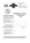
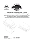
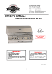
OUTDOOR GAS BARBEQUE OWNER’S MANUAL This manual is for use with Jackson Grills 3 & 4 Burner Models MODELS JG3 AND JG4 Warning: Please read and understand the contents of this manual fully before operating. Failure to do so may result in fire or explosion. Homeowners should retain these instructions. CONTENTS A Message to our Customers.................. 2 Safety .................................................... 3 Installation ............................................ 3 Clearances ............................................. 4 LP Gas Cylinder...................................... 4 Specifications ........................................ 4 OPD Equipped Cylinder .......................... 6 Hose and Regulator ............................... 6 Leak Testing .......................................... 8 Gas Conversion ...................................... 8 Maintenance .......................................... 9 Lighting Instructions ........................... 11 Trouble Shooting ................................. 12 Warranty ............................................. 13 Proudly Manufactured By: Jackson Grills Inc. G2-4970 Polkey Rd. Phone: 1-250-715-0820 Duncan, B.C. Fax: V9L 6W3 Email: [email protected] 1-250-715-0821 A special message to our customers Thank you for choosing the Jackson Grill for your new gas grill. This appliance is designed with quality components and we are confident that it will provide you with years of excellent operation. Please take the time to read the whole manual and familiarize yourself with all of the features of the Jackson Grill. This manual also contains important safety information and operation instructions. Ensure that this manual remains handy to the barbeque for quick reference. If you need to obtain replacement parts for your Jackson Grill, contact your local dealer. NOTE: It is normal for stainless steel surfaces to discolor due to high heat given off from the barbeque burners. Please take the time to fill out and return the Ownership and Registration Card below. It can be mailed to: Jackson Grills Inc. G2-4970 Polkey Road, Duncan, B.C. V9L 6W3 or fax: 1-250-715-0821 Please complete and return within 10 days. Thank you. Mr. Mrs. Ms. First Name: Miss Initial: Street: Last Name: Apt. #: City: State/Province: Phone: Email: Date of Purchase: Dealer: Model: Serial #: Zip/Postal: Comments: Thank you for taking the time to fill out this Ownership and Registration Card. 2 SAFETY Your new Jackson Grill barbeque is a safe, convenient appliance when used and maintained properly. As with all gas-fired appliances, certain safety precautions must be observed. Failure to follow these precautions may result in damage or injury. If you have any questions or concerns regarding the assembly or operation of this appliance, you should contact your dealer, gas appliance technician or your gas company. NEVER OPERATE THIS BBQ WITHOUT THE PULL OUT MAIN DRIP TRAY IN PLACE. FOR YOUR SAFETY If you smell gas: 1. Shut off gas to the appliance. 2. Extinguish any open flame. 3. Open lid. 4. If odor continues, immediately call your supplier or fire department. DO NOT store or use gasoline or any other flammable liquid in the vicinity of this or any other appliance. An LP Cylinder not connected for use shall not be stored in the vicinity of this or any other appliance. CAUTION 1. For outdoor use only. 2. If stored indoors, detach and leave cylinder outdoors. 3. This appliance must not be operated unattended. 4. Special care must be taken to keep small children away from heated surfaces. ELECTRICAL CAUTION 1. If any accessory is used on this appliance with an external electrical power source, the accessory (when installed) must be electrically grounded in accordance with local codes. In the absence of local codes, the following standards apply: (Canada) CSA C22.1 Canadian Electrical Code, and (USA) ANSI/NFPA No. 70 – Latest Edition. 2. Do not cut or remove the grounding prong from the plug. 3. Keep the electrical supply cord and fuel supply hose away from any heater surface. INSTALLATION In Canada, this appliance must be installed in accordance with the local code and relevant CGA standards: CAN/CGA-B149.1 LP Gas/Propane Installation Code and latest codes where applicable. In the USA, this appliance must be installed in accordance with the local code and relevant national code: ANSI Z223.1 – Latest Edition National Fuel Gas Code. CLEARANCES 1. The appliance must have a minimum horizontal clearance from sides and back of unit to adjacent vertical combustible construction below and extending above the top of the unit 36 inches from sides and 36 inches from back of unit. 2. Do not locate this appliance under any overhead unprotected combustible construction. 3. This appliance is for outdoor use only. Do not operate in garage, shed, balcony or other such enclosed areas. QCC-1 Quick Closing Coupling system. The QCC-1 system incorporates new safety features required by the Canadian Standards Steering Committee and the American National Standards Institute (ANSI). Gas will not flow until a positive connection has been made. A thermal element will shut off flow of gas between 240 degrees and 300 degrees F. When activated, a flowlimiting device will limit the flow of gas to 10 cubic feet per hour. 4. Do not restrict or obstruct the flow of combustible and ventilation air to the appliance. 5. Keep the area surrounding the appliance free of combustible materials, gasoline and all flammable liquids and vapours. 6. This appliance is not intended to be installed in or on recreational vehicles and/or boats. LP GAS CYLINDER PLACEMENT Cylinders must be installed according to assembly instructions. Install the gas cylinder into the tank hole inside of the Jackson Pedestal. LP GAS CYLINDER QCC-1 Quick Closing Coupling Your grill is designed to be used with an LP gas cylinder equipped with the new The LP Gas Cylinder is not included with the Gas Grill. Be sure to purchase one with the QCC valve. This valve is recognized by the external threads on the inlet port of the valve. QCC equipped cylinders are available from your gas grill dealer. Any attempt to connect the regulator, by use of adapters or any other means, to any other valve could result in damage or fire, and may negate the important safety features designed into the QCC-1 system. SPECIFICATIONS 1. All LP gas cylinders used with this appliance must be constructed and marked with the specifications for LP cylinders in accordance with the Canadian Transport Commission (CTC) 4 or the US Department of Transport (DOT) for use in the USA. 2. The LP gas cylinder used for this appliance must not have a capacity larger than 20 lb. (9 kg): approximately 18” (46cm) high & 12” (30cm) diameter. 3. All LP gas cylinders used with this appliance should be inspected at every filling and re-qualified by a licensed service outlet at the expiry date (10 years) in accordance with DOT (USA) and CTC (Canada) codes for LP gas cylinders. 4. All LP gas cylinders used with the appliance must be provided with a shut off valve terminating in a cylinder valve outlet No. 510, specified in the Standard for Compressed Gas Cylinder Valve Outlet and Inlet Connections (USA) ANSI / CGA-V-11977 (Canada) CSA B96. The cylinder supply system must be arranged for vapor withdrawal. The cylinder must also include a collar to protect the cylinder valve. As well, the cylinder valve must include a safety relief device having direct communication with the vapor space of the cylinder. HANDLING 1. Government regulations prohibit shipping full LP gas cylinders. You must take your new cylinder to an LP gas dealer for filling. position. Protect accidental damage. the valve from 3. Do not tip the LP gas cylinder while connecting it to the regulator. Fasten the cylinder securely during transport, use and storage. 4. If the cylinder is tipped after it is connected to the regulator, shut off the gas, disconnect the regulator and have it checked before using it again. STORAGE 1. Store the LP gas cylinders outdoors in a well-ventilated area. 2. Do not store the LP gas cylinders in direct sunlight or near a source of heat or combustion. 3. If you intend to store your grill indoors, disconnect and remove the LP gas cylinder first. Disconnected cylinders must have plugs installed and must not be stored in a building, garage or any other enclosed area. 4. Keep out of reach of small children. 5. When the LP gas cylinder is connected to the gas grill, the LP gas cylinder must be stored outside in a wellventilated area. 6. Keep the ventilation openings for the LP cylinder enclosure free and clear of debris. 2. A filled LP gas cylinder is under very high pressure. Always handle with care and transport in the upright 5 OPERATION IDENTIFICATION 1. Never connect your gas grill to an LP cylinder without the regulator provided, and never to an unregulated gas supply. The gas regulator supplied with the appliance must be used. To identify these cylinders, the new OPD handwheel has been standardized to the shape shown. 2. Always leak test the LP gas cylinder to regulator connection when connecting the LP gas cylinder to the appliance. See “leak testing”. 3. Do not operate the appliance if the smell of LP gas is present. Extinguish all flame and determine the source of LP gas before proceeding. Do not ignite the appliance until the LP gas leak has been found and sealed. 4. Always shut off the LP gas cylinder valve when the appliance is not in use. OPD EQUIPPED CYLINDER Effective January 1, 1998, the standard for outdoor gas appliances, ANSI Z21.58/CAN CGA-1.6, requires that appliances are to be used with cylinders equipped with an Overfill Prevention Device (OPD). The OPD is designed to reduce the potential for the overfilling of propane cylinders, thus reducing the possibility of relief valve discharges of raw propane. The new OPD causes a slower purge / fill operation. Some consumers have been advised by filling stations that these cylinders are “defective”. This is not a defect. Some propane filling stations may not be aware of this new device and its effects on the purge / fill operation. HOSE AND REGULATOR 1. The QCC coupling contains a magnetic Flow Limiting Device which will limit the flow of gas should there be a leak between the regulator and the appliance valve. This device will activate if the cylinder valve is opened while the appliance valves are open. Be sure the appliance valves are off before the cylinder valve is opened to prevent accidental activation. 2. The QCC coupling incorporates a heat sensitive hand wheel that will cause the back check module in the QCC cylinder valve to close when exposed to temperatures between 240 degrees and 300 degrees F. Should this occur, do not attempt to reconnect the nut. Remove the hose / regulator assembly and replace with a new one. 3. The pressure regulator is set at 11” (water column) and is for use with LP 6 gas only. The hose and hose couplings comply with CGA Standard CAN 1.83. No modifications or substitutions should be attempted. 4. Protect the hose from dripping grease and do not allow the hose to touch any hot surface, including the base of the grill. 5. Inspect the seal in the QCC cylinder valve when replacing the LP gas cylinder or once per year, which ever is more frequent. Replace the seal if there is any indication of cracks, creases or abrasions. 6. Inspect the hose before each use of the appliance. If the hose is cracked, cut, damaged or abraded in any way, the appliance must not be operated. 7. For repair or replacement of hose / regulator assembly, contact your dealer or approved service center. CONNECTION 1. Be sure the cylinder valve appliance valves are “off”. and 2. Place full LP gas cylinder on tank ring bracket. until there is a positive stop. Do not use tools. Hand tighten only. When making the connection, hold the regulator in a straight line with the cylinder valve, so as not to cross thread the connection. 4. Leak test the connection. test”. See “leak 5. Refer to lighting instructions. To avoid activating the Flow Limiting Device when lighting, open the cylinder valve slowly with the appliance valves off. If the Flow Limiting Device is accidentally activated, turn off cylinder valve and appliance valves, wait 10 seconds to allow the device to reset, open cylinder valve slowly, then open the appliance valve. IMPORTANT SAFETY INFORMATION THE PRESSURE REGULATOR AND HOSE ASSEMBLY SUPPLIED WITH THIS OUTDOOR COOKING APPLIANCE MUST BE USED. REPLACEMENT PRESSURE REGULATORS AND HOSE ASSEMBLIES MUST BE THOSE SPECIFIED BY THE OUTDOOR COOKING GAS MANUFACTURER. 1. Do not store a spare LP-gas cylinder under or near this appliance. 2. Never fill the cylinder beyond 80% full. IF THE INFORMATION IN “A” AND “B” IS NOT FOLLOWED EXACTLY, A FIRE CAUSING DEATH OR SERIOUS INJURY MAY OCCUR. 3. Center the nipple in the cylinder valve and hold in place. Using the other hand, turn the hand wheel clockwise 7 NATURAL GAS INSTALLATIONS LEAK TEST 1. DO NOT USE OR PERMIT SOURCES OF IGNITION IN THE AREA WHILE DOING THE LEAK TEST. THIS INCLUDES SMOKING. 2. Leak testing should be done once per year or whenever the LP gas cylinder or any other gas system part is replaced, whichever is more frequent. 3. The leak testing solution should be half liquid detergent and half water. 4. Apply the solution to the LP gas delivery system at points shown in the illustration. 5. Bubbles in the soap solution indicate that a leak is present. 6. The leak(s) must be stopped by tightening the loose joints, if possible, or by replacing the faulty parts(s) with the part(s) recommended by the appliance manufacturer. THE APPLIANCE IS NOT TO BE USED UNTIL ANY LEAK IS CORRRECTED. 7. A gas appliance repairman or LP gas dealer should be called if attempts to stop the leak(s) are unsuccessful and, in such case, the LP gas supply must be shut off at the cylinder valve or the cylinder must be removed from the appliance until the leak(s) is corrected. The outdoor cooking gas appliance and its’ individual shut off valve must be disconnected from the gas supply piping system during any pressure testing of that system at test pressures in excess of ½ psi (3.5 kPa). The outdoor cooking gas appliance must be isolated from the gas supply by closing its’ individual manual shut off valve during any pressure testing of the gas supply piping system at test pressures equal to or less than ½ psi (3.5 kPa). CONVERSION PROPANE (LP) TO NATURAL GAS All gas conversion should be performed by a qualified gas fitter. This appliance should only be converted with conversion kit CON-4 GAS VALVES AND ORIFICES 1. Remove gas control knobs by pulling the knobs straight off. 2. Remove the control cover by unscrewing the two screws located on each end of the front control area. 3. Lift off the cover and set carefully to one side. Be careful not to disconnect or cut electrode wires. 4. Remove the manifold bracket screws located on the under side of the control panel area. 5. Lift the manifold slightly out of position by pulling it away from the burners. 8 This will allow the orifices to disengage from the burner venturi. 6. Unscrew each gas valve and re-install new natural gas valves and orifices. Use teflon tape or pipe dope when installing valves and orifices. GAS LINE Remove the 3/8” flare fitting that attaches the propane hose from the fitting block inside of the pedestal and replace with an approved 10’ neopream hose. Make sure when the new gas valves are installed that they have a bright silver face near the stem of the gas valve. This identifies them as Natural Gas valves. REMEMBER TO LEAK CHECK ALL FITTINGS. AFTER ALL OF THE CONVERSION IS COMPLETED, LEAK CHECK ALL FITTINGS AND TEST FIRE ALL BURNERS TO ENSURE PROPER, SAFE OPERATION. MAINTENANCE Burner Inspection We recommend that the gas burners be inspected and cleaned once a year. Burner Removal for Cleaning 1. Ensure the gas supply is off and grill is cool. 2. Remove cooking grates and flame tamers. 3. Remove burner mounting screw located at the very back of burner near the rear of the firebox. 4. Remove burners by lifting up and out of firebox on an angle. Repeat for all burners. 5. Clean the outside of the burners with a wire brush and make sure all gas ports are clear. Use a straight coat hanger to clear any obstructions. 6. Use a flashlight to look into the venturi end of the burner to check for blockages. If necessary, use a straight coat hanger to clear any obstructions. 7. Inspect and clean the venturi end of the burner by removing the venturi set screw on the end of the burner and removing the venturi shutter. Once removed, make sure the burner is thoroughly cleaned and the venturi shutter is re-installed with an opening of 1/8” for Natural Gas and ¼” for Propane. 8. Re-install and secure burner. 9. Re-mount flame tamers and cooking grids. 10. Light each burner to ensure they are operating correctly. Note: When installing burners, it is very important to center the burner over the gas orifice. You should look under the main control panel with a flashlight once installed to make sure they are in the proper position. Failure to clean and install burners correctly could result in fire or explosion. HELPFUL HINTS FOR CLEANING THE COOKING GRILLS Do not clean the cooking surface once the grill has cooled down. Allow cooking residues to remain on the surface until the next time you grill, then do a pre-burn for 10 minutes prior to grilling. Remove 9 charred remains with a wire brush or scraper. When used for the first time, the grill will emit a slight odor. This is a normal and temporary condition caused by the burn-in of internal paints and lubricants used in the manufacturing process and should not occur again. Simply run the main burners on high for approximately ½ hour with the lid open. MAIN BURNER LIGHTING Light each burner by turning the control valve to the high / light position and firmly depress the ignition control button. You should hear the “clicking” sound of the ignitor and the burner should light within a few seconds. Light the left-hand burner first, then complete the same steps for lighting the other burners. 1. Always open the lid when lighting the burners. 2. Turn the left burner to high / light. Press and hold ignitor button until the burner lights. 3. If the burner does not immediately light, turn the valve to OFF. Wait 5 minutes then repeat lighting procedures. 4. Repeat these steps for lighting each burner. Manual Burner Lighting Main Burner See your local dealer for service if your grill ignitor is not functioning. 1. Remove the cooking grates and the flame tamers that are over each burner. 2. Turn the burner you are lighting to high / light and place a long match near the side gas ports of the burner. 3. If the burner does not immediately light, turn the valve to OFF. Wait 5 minutes then repeat lighting procedures. REAR BURNER LIGHTING (If equipped) 1. Light the rear burner by placing a long match next to the gas ports on the rear burner then turn on the right hand “rear” control knob to high. 2. If the burner does not immediately light, turn valve to OFF. Wait 5 minutes then repeat lighting procedures. MAIN BURNER USE When searing foods, preheating is recommended by operating all main burners in the high position with the lid closed for approximately 10 minutes. Cooking with the lid closed will ensure a more even temperature that will reduce cooking time and cook more evenly. Food that has a cooking time longer than 30 minutes, such as roasts, may be cooked indirectly (with the burner lit opposite the food placement). When cooking very lean meats, such as chicken breasts or lean pork, the grids can be oiled before cooking to prevent sticking. Cooking meat with a high degree of fat content may create flare-ups. Either trim some fat or reduce temperatures to prevent this. Should a flare up occur, move the food away from the flames, reduce heat and leave the lid open. 10 LIGHTING INSTRUCTIONS OPEN LID ┌ Ensuring all burner controls are in the off position, slowly turn on the gas supply valve. MAIN BURNER LIGHTING ┐ REAR BURNER LIGHTING Turn any main burner control to high position. Remove warming rack. Depress Igniter button and hold or light with a match. Turn rear burner control to high positionand light with a match. If ignition is not immediate, turn burner control off. Wait 5 minutes. If ignition is not immediate, turn burner control off. Wait 5 minutes. └ With left burner operating on high, turn the center and / or right burner to high. ┘ 11 TROUBLE SHOOTING PROBLEM POSSIBLE CAUSES SOLUTION Low heat or low flame when valve turned to high. For propane – improper lighting procedure. Ensure lighting procedure is followed carefully. All gas grill valves must be in the off position when the tank valve is turned on. Turn tank on for all pressure to equalize. See lighting instructions. For natural gas – undersized supply line. Pipe must be sized according to installation code. For both gases – improper preheating. Pre-heat grill with all main burners on high for 10-15 minutes. Flame tamers incorrectly. Ensure flame tamers are located in slots in front firebox and inline with burners. Excessive flare-ups or un-even heat. installed Improper pre-heating. Pre-heat grill with all main burners on high for 10-15 minutes. Excessive great on sear plates and in drip pan. Clean flame tamers and drip pan regularly. Do not line pan with aluminum foil. Refer to cleaning instructions. Burners burn with yellow flame, accompanied by smell of gas. Possible spider web or other debris. Thoroughly clean burner by removing. See maintenance instructions. Burner will not light with ignitor but will light with match. Dead battery in ignitor. Change battery by turning ignitor cover clockwise to remove. Install one AA battery. Loose electrode wire. Check electrode wire is firmly pushed onto the terminal on the back of the ignitor. Improper gap at electrode tip. Ensure the collector box is tight and the gap between the electrode end and the collector box is between 1/8” and 3/16”. The gap can be adjusted by bending the box in or out. Normal occurrence on hot days. This is not a defect. It is caused by internal vibrations in the regulator and does not effect the performance or safety of the gas grill. Humming Regulator. 12