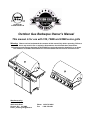
1
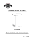
Certified for Canada and U.S.A Outdoor Gas Barbeque Owner’s Manual This manual is for use with 700, 700BI and 850BI series grills Warning: Please read and understand the contents of this manual fully before operating. Failure to do so may result in fire or explosion. Homeowners should retain these instructions. All barbecues and carts are designed for OUTDOOR use only and cannot be installed in or on boats. This barbecue is CANNOT be installed in or on Recreational Vehicles. Not for commercial use. Manufactured by: Jackson Grills Inc. 2945 Jacob Road Duncan, B.C. V9L 6W4 Email: [email protected] Phone: 1-250-715-0820 Fax: 1-250-715-0821 TABLE OF CONTENTS: SAFETY. LP GAS CYLINDER REPLACEMENT. OPD EQUIPPED CYLINDER. HOSE AND REGULATOR. LEAK TESTING. INSTALLATION. CLEARANCES. ASSEMBLY. GETTING TO KNOW YOUR GRILL LIGHTING INSTRUCTIONS. GAS CONVERSION. MAINTENANCE. GRILLING TIPS AND TECHNIQUES. TROUBLE SHOOTING. PARTS LIST. EXPLODED VIEWS. WARRANTY. A MESSAGE TO OUR CUSTOMERS. 3 4-5 6 6 7 8 9 10-13 14 15 16-18 19 20 21 22 23 24 25 DO’S AND DON’TS DO… ¾ ¾ ¾ ¾ ¾ ¾ ¾ ¾ ¾ ¾ ¾ DON’T… Have propane cylinder (LP Units) filled by an authorized LP supplier. Check all gas connections for leaks using a soapy water solution before lighting, tighten connections until the bubbles disappear. Always open the hood before lighting. Pre heat the grills before using. After cooking, turn the grill OFF, then take a long handled soft wire brush and brush off the cooking grills, then turn off the gas at the main fuel supply. Cook with the hood down when possible. It is faster and more efficient. Trapped smoke adds flavor. Turn the gas supply off immediately if you are unable to light the grill. Wait 5 minutes before attempting to light the grill again. Have proper tools. Tongs, mittens ready prior to removing food. Trim excess fat from meats to minimize flare-ups. Let the grill totally cool before cleaning or removing any parts for cleaning or servicing. Cover the grill with the cover when not in use. ¾ ¾ ¾ ¾ ¾ ¾ ¾ ¾ ¾ ¾ ¾ ¾ 2 Install the grill closer than 36 “ on the sides and back to any combustible materials. Attempt to adjust the Regulator, it has been factory set and tested. Allow a LP gas cylinder to lie on its side. Keep in an upright position. Turn a control valve on before the igniter button has been depressed. Use plastic or un-tempered glass utensils on or in the grill. Attempt to move an Aluminum foil pan while it is still hot. Cover or block any air opening. Place aluminum foil in the grease pan to catch the drippings. Wear long, loose flowing clothing around the grill. Long flowing hair is also easily ignited. Put food on the grill and leave it unattended or unwatched for long periods of time. Use CAUSTIC materials to clean the grill. Example: Lye, or solvents. Never use the warming rack in place while using the rear infrared burner. SAFETY: Your new Jackson Grill barbeque is a safe, convenient appliance when used and maintained properly. As with all gas-fired appliances, certain safety precautions must be observed. Failure to follow these precautions may result in damage or injury. If you have any questions or concerns regarding the assembly or operation of this appliance, you should contact your dealer, gas appliance technician or your gas company. NEVER OPERATE THIS BBQ WITHOUT THE PULL OUT MAIN DRIP TRAY IN PLACE. FOR YOUR SAFETY: If you smell gas: 1. Shut off gas to the appliance. 2. Extinguish any open flame. 3. Open lid. 4. If odor continues, immediately call your supplier or fire department. DO NOT store or use gasoline or any other flammable liquid in the vicinity of this or any other appliance. An LP Cylinder not connected for use shall not be stored in the vicinity of this or any other appliance. CAUTION: 1. For outdoor use only. 2. If stored indoors, detach and leave cylinder outdoors. 3. This appliance must not be operated unattended. 4. Special care must be taken to keep small children away from heated surfaces. ELECTRICAL CAUTION: 1. If any accessory is used on this appliance with an external electrical power source, the accessory (when installed) must be electrically grounded in accordance with local codes. In the absence of local codes, the following standards apply: (Canada) CSA C22.1 Canadian Electrical Code, and (USA) ANSI/NFPA No. 70 – Latest Edition. 2. Do not cut or remove the grounding prong from the plug. 3. Keep the electrical supply cord and fuel supply hose away from any heater surface. 3 LP GAS CYLINDER PLACEMENT: Cylinders must be installed according to assembly instructions. Install the gas cylinder into the tank hole inside of the Jackson Pedestal. LP GAS CYLINDER: QCC-1 Quick Closing Coupling Your grill is designed to be used with an LP gas cylinder equipped with the new QCC-1 Quick Closing Coupling system. The QCC-1 system incorporates new safety features required by the Canadian Standards Steering Committee and the American National Standards Institute (ANSI). Gas will not flow until a positive connection has been made. A thermal element will shut off flow of gas between 240 degrees and 300 degrees F. When activated, a flow-limiting device will limit the flow of gas to 10 cubic feet per hour. The LP Gas Cylinder is not included with the Gas Grill. Be sure to purchase one with the QCC valve. The external threads on the inlet port of the valve recognize this valve. QCC equipped cylinders are available from your gas grill dealer. Any attempt to connect the regulator, by use of adapters or any other means, to any other valve could result in damage or fire, and may negate the important safety features designed into the QCC-1 system. SPECIFICATIONS: All LP gas cylinders used with this appliance must be constructed and marked with the specifications for LP cylinders in accordance with the Canadian Transport Commission (CTC) 1. or the US Department of Transport (DOT) for use in the USA. 2. The LP gas cylinder used for this appliance must not have a capacity larger than 20 lb. (9 kg): approximately 18” (46cm) high & 12” (30cm) diameter. 3. All LP gas cylinders used with this appliance should be inspected at every filling and re-qualified by a licensed service outlet at the expiry date (10 years) in accordance with DOT (USA) and CTC (Canada) codes for LP gas cylinders. 4. All LP gas cylinders used with the appliance must be provided with a shut off valve terminating in a cylinder valve outlet No. 510, specified in the Standard for Compressed Gas Cylinder Valve Outlet and Inlet Connections (USA) ANSI / CGA-V-11977 (Canada) CSA B96. The cylinder supply system must be arranged for vapor withdrawal. The cylinder must also include a collar to protect the cylinder valve. As well, the cylinder valve must include a safety relief device having direct communication with the vapor space of the cylinder. 4 HANDLING: 1. Government regulations prohibit shipping full LP gas cylinders. You must take your new cylinder to an LP gas dealer for filling. 2. A filled LP gas cylinder is under very high pressure. Always handle with care and transport in the upright position. Protect the valve from accidental damage. 3. Do not tip the LP gas cylinder while connecting it to the regulator. Fasten the cylinder securely during transport, use and storage. 4. If the cylinder is tipped after it is connected to the regulator, shut off the gas, disconnect the regulator and have it checked before using it again. STORAGE: 1. Store the LP gas cylinders outdoors in a well-ventilated area. 2. Do not store the LP gas cylinders in direct sunlight or near a source of heat or combustion. 3. If you intend to store your grill indoors, disconnect and remove the LP gas cylinder first. Disconnected cylinders must have plugs installed and must not be stored in a building, garage or any other enclosed area. 4. Keep out of reach of small children. 5. When the LP gas cylinder is connected to the gas grill, the LP gas cylinder must be stored outside in a well-ventilated area. 6. Keep the ventilation openings for the LP cylinder enclosure free and clear of debris. OPERATION: 1. Never connect your gas grill to an LP cylinder without the regulator provided, and never to an unregulated gas supply. The gas regulator supplied with the appliance must be used. 2. Always leak test the LP gas cylinder to regulator connection when connecting the LP gas cylinder to the appliance. See “leak testing”. 3. Do not operate the appliance if the smell of LP gas is present. Extinguish all flame and determine the source of LP gas before proceeding. Do not ignite the appliance until the LP gas leak has been found and sealed. 4. Always shut off the LP gas cylinder valve when the appliance is not in use. 5 OPD EQUIPPED CYLINDER: Effective January 1, 1998, the standard for outdoor gas appliances, ANSI Z21.58/CAN CGA-1.6, requires that appliances are to be used with cylinders equipped with an Overfill Prevention Device (OPD). The OPD is designed to reduce the potential for the overfilling of propane cylinders, thus reducing the possibility of relief valve discharges of raw propane. The new OPD causes a slower purge / fill operation. Some consumers have been advised by filling stations that these cylinders are “defective”. This is not a defect. Some propane filling stations may not be aware of this new device and its effects on the purge / fill operation. IDENTIFICATION: To identify these cylinders, the new OPD hand wheel has been standardized to the shape shown. HOSE AND REGULATOR: 1. The QCC coupling contains a magnetic Flow Limiting Device which will limit the flow of gas should there be a leak between the regulator and the appliance valve. This device will activate if the cylinder valve is opened while the appliance valves are open. Be sure the appliance valves are off before the cylinder valve is opened to prevent accidental activation. 2. The QCC coupling incorporates a heat sensitive hand wheel that will cause the back check module in the QCC cylinder valve to close when exposed to temperatures between 240 degrees and 300 degrees F. Should this occur, do not attempt to reconnect the nut. Remove the hose / regulator assembly and replace with a new one. The pressure regulator is set at 11” (water column) and is for use with LP 3. gas only. The hose and hose couplings comply with CGA Standard CAN 1.83. No modifications or substitutions should be attempted. 4. Protect the hose from dripping grease and do not allow the hose to touch any hot surface, including the base of the grill. 5. Inspect the seal in the QCC cylinder valve when replacing the LP gas cylinder or once per year, which ever is more frequent. Replace the seal if there is any indication of cracks, creases or abr 6. Inspect the hose before each use of the appliance. If the hose is cracked, cut, damaged or abraded in any way, the appliance must not be operated. 7. For repair or replacement of hose / regulator assembly, contact your dealer or approved service center. CONNECTION: 1. Be sure the cylinder valve and appliance valves are “off”. 2. Place full LP gas cylinder on tank ring bracket. 3. Center the nipple in the cylinder valve and hold in place. Using the other hand, turn the hand wheel clockwise until there is a positive stop. Do not use tools. Hand tighten only. When making the connection, hold the regulator in a straight line with the cylinder valve, so as not to cross thread the connection. 6 4. Leak test the connection. See “leak test”. 5. Refer to lighting instructions. To avoid activating the Flow Limiting Device when lighting, open the cylinder valve slowly with the appliance valves off. If the Flow Limiting Device is accidentally activated, turn off cylinder valve and appliance valves, wait 10 seconds to allow the device to reset, open cylinder valve slowly, then open the appliance valve. IMPORTANT SAFETY INFORMATION; THE PRESSURE REGULATOR AND HOSE ASSEMBLY SUPPLIED WITH THIS OUTDOOR COOKING APPLIANCE MUST BE USED. REPLACEMENT PRESSURE REGULATORS AND HOSE ASSEMBLIES MUST BE THOSE SPECIFIED BY THE OUTDOOR COOKING GAS MANUFACTURER. A. Do not store a spare LP-gas cylinder under or near this appliance. B. Never fill the cylinder beyond 80% full. IF THE INFORMATION IN “A” AND “B” IS NOT FOLLOWED EXACTLY, A FIRE CAUSING DEATH OR SERIOUS INJURY MAY OCCUR. LEAK TEST: 1. DO NOT USE OR PERMIT SOURCES OF IGNITION IN THE AREA WHILE DOING THE LEAK TEST. THIS INCLUDES SMOKING. 2. Leak testing should be done once per year or whenever the LP gas cylinder or any other gas system part is replaced, whichever is more frequent. 3. The leak testing solution should be half liquid detergent and half water. 4. Apply the solution to the LP gas delivery system at points shown in the illustration. 5. Bubbles in the soap solution indicate that a leak is present. 6. The leak(s) must be stopped by tightening the loose joints, if possible, or by replacing the faulty parts(s) with the part(s) recommended by the appliance manufacturer. THE APPLIANCE IS NOT TO BE USED UNTIL ANY LEAK IS CORRECTED. A gas appliance repairman or LP gas dealer should be called if attempts to stop the leak(s) are unsuccessful and, in such case, the LP gas supply must be shut off at the cylinder valve or the cylinder must be removed from the appliance until the leak(s) is corrected. 7 INSTALLATION: In Canada, this appliance must be installed in accordance with the local code and relevant CGA standards: CAN/CGA-B149.1 LP Gas/Propane Installation Code and latest codes where applicable. In the USA, this appliance must be installed in accordance with the local code and relevant national code: ANSI Z223.1 – Latest Edition National Fuel Gas Code. CLEARANCES and DIMENSIONS: 1. The appliance must have a minimum horizontal clearance from sides and back of unit to adjacent vertical combustible construction below and extending above the top of the unit 36 inches from sides and 36 inches from back of unit. 2. Do not locate this appliance under any overhead, unprotected combustible construction. 3. This appliance is for OUTDOOR USE ONLY. Do not operate in garage, shed, balcony or other such enclosed areas. 4. Do not restrict or obstruct the flow of combustible and ventilation air to the appliance. 5. Keep the area surrounding the appliance free of combustible materials, gasoline and all flammable liquids and vapors. 6. This appliance is not to be installed in or on recreational vehicles and/or boats. UNIT DIMENSIONS 700 850 BI A 57.50” 40.5” B 47.5” 21.75” C 25.78” D 56” E 23.35” F 47.5” 23.375” 850 Built In Model 8 INSTALLING 700BI / 850BI INTO A NON COMBUSTIBLE ISLAND. ALL DIMENSIONS ARE IN INCHES: 700BI 850 BI A 32.5 39.5 B 9.25” 9.25” C 17” 17” D 10.25” 10.25” E 3” 3” F 17.25” 17.25” G 24.25” 24.25” H 24” min. 24” min. I 18.5” 18.5” J 5.5” min 5.5” min INSTALLING 700BI / 850BI INTO A COMBUSTIBLE ISLAND. NOTE: IMPORTANT!!! If these units are to be installed into a COMBUSTIBLE island a Zero Clearance Box MUST be installed. These Zero Clearance boxes are only available through your local dealer or Jackson Grills Inc. Use Part numbers: #ZCAN700 / #ZCAN850 for installations into Combustible Islands. 700BI ZC 850 BI ZC A 34.75*** 41.75*** B 9.25” 9.25” C 17” 17” D 10.25” 10.25” E 3” 3” F 17.25” 17.25” G 24.25” 24.25” H 24” min. 24” min. I 19.5*** 19.5*** J 5.5” min 5.5” min *** Difference between Non Combustible and Combustible Island Installations. Ensure that the constructed island is well secured and that this island is level in all directions. Place the grill into the cut out located in the island. Connect the gas line to the gas grill located on the left hand side of this grill. Perform a gas leak test on this connection to ensure a gas leak is not present. NOTE: PLEASE ENSURE ALL PACKAGING MATERIALS HAVE BEEN REMOVED FROM ALL SURFACES. 9 ASSEMBLY: Please ensure the proper tools are used for ease of installation. Some assembly will be required if this unit is installed in a pedestal. Please remove all components from the packaging and inspect all components to ensure there is no damage to any components in the packaging. If damage is present please contact you local dealer for replacement components. Please replace all damaged components with original manufacturer’s parts only no substitutions will be permitted. Please remove all packaging from all components of the gas grill before operating. TOLLS REQUIRED FOR ASSEMBLY: # 2 Phillips Screwdriver 8 mm Open Ended Wrench 2- 3/4” Open Ended Wrenches Adjustable Wrench SIDE SHELF INSTALLATION. ¾ ¾ ¾ ¾ ¾ ¾ ¾ ¾ ¾ Remove the securing straps from the front of the Display Panel and the pedestal side ( X 2). Do not throw away these fasteners. Remove the 4 Phillips head screws from each side of the pedestal. Loosen the 2- 8 mm bolts at the top of each pedestal side. (Do Not Remove) Carefully remove the Side Shelves from the packaging. The Side Shelf that contains the Side Burner will ALWAYS be installed on the Left hand side of the Grill as you are facing the grill. Install the side shelves buy dropping the Side Shelf over the 8 mm bolts. (do not tighten these 8 mm bolts). Install the 4 Phillips head screws to secure the Side Shelf in place. Tighten the 2 – 8 mm bolts to finish the side shelf installation. Repeat for the other side. Connect the gas line from the inside of the pedestal to the Side Burner outlet located under the Left Side Shelf. Use 2 - 3/4” wrenches to properly secure the gas line to the Side Burner Gas Valve assembly. NOTE: The Condiment bin is already attached to the side shelf as an assembly. 2 – 8mm bolts. Loosen but Do Not remove 4 – Phillips head Screws. Remove and reinstall after side shelf has been installed on the 2 8 mm bolts at the top 10 After the Side Shelves have been installed, ensure the Grill Head is pushed back in the pedestal as far as possible. With the screws removed from the securing straps, place a screw through the side of the Condiment bins and secure the Condiment Bins to the Display Panel. Secure the Condiment Bins to the Display Panel using the screws from the securing plates. ROTISSERIE KIT INSTALLATION (If Equipped) 1 Install the Motor Mounting Bracket supplied to the Right hand side of the Inner Hood. (If not already installed) Install the Motor on the Motor Bracket. Place the Rotisserie Rod into the Motor. Slide the Rotisserie Rod Bushing over the opposite end of the Rod and drop into the cut out provided in the inner Hood Side. Tighten the thumb-screw provided with the Rotisserie Rod Bushing. Place the forks and Counter Balance on the Rotisserie Rod in the desired location. When in use, spin the rod with your desired food until the weight of the food is at the bottom. Install the Counter Balance Straight up to effectively balance the Rotisserie system. 2 3 4 5 1 2 3 4 5 6 7 Rotisserie Rod Handle Rotisserie Rod Bushing Counter Balance Rotisserie Forks X 2 Rotisserie Rod Rotisserie Motor Mount Rotisserie Motor 11 Rotisserie Kit Completed Installation Rotisserie Rod Bushing Placed on the cut out provided on the Inner Hood Upper Flavor Shield, Cooking Grid Installation. Remove the Upper Flavor Shields form the Packaging. Please ensure that all protective plastic has been removed from these parts. These Upper Flavor shields should be placed on the pins provided on the Firebox Front and Rear. Ensure that all of the Upper Flavor Shields have been installed correctly on the pins provided or the unit will not work correctly. See diagram below. Once the Upper Flavor Shield have been installed the Cooking Grids can be installed into the Grill. Place the cooking grills on the upper ledge of the firebox as shown below. Upper Flavor Shield installation. Place the Upper Flavor Shields on the pins provided on the Firebox Front and Rear Cooking Grid Installation. Place the Cooking Grids X 2 on the upper ledge as shown. 12 Main Gas Line Connections for Propane Gas and Natural Gas. The main Fuel supply gas line is connected to a Manifold Tee securely mounted inside the pedestal located on the left hand side of the pedestal. Remove the Propane hose and regulator assembly from the packaging. Please ensure that there is no debris inside the brass flare connection or inside the rubber hose. Using a ¾” wrench and an adjustable wrench tighten the Hose to the connection provided inside the pedestal. If this unit is to be connected to Natural Gas, place the Natural Gas hose through the hole provided in the lower left hand rear corner of the pedestal. This hole should have a rubber grommet around the hole to protect the Hose from getting damaged. See diagram below. Place the Propane Hose and regulator on the Manifold located inside the pedestal. For Natural Gas hose installations, place the hose through the hole in the back of the pedestal and connect in the same location as the Propane Hose location. Once the Main Gas line has been connected, connect the fuel line to the Gas supply being used. Turn the gas on SLOWLY, if the gas is turned on too quickly the Regulator could lock up and not work correctly. By turning the main gas supply on slowly this will prevent this problem form happening. When the gas supply has been turn on, perform a Leak Check on ALL connections inside the pedestal using a Soapy water solution as described on Page 7 of this manual. 13 Getting To Know Your Grill. 1 2 3 4 5 6 7 8 9 10 Outer Hood Handle Hood Thermometer Outer Hood Cooking Grids Side Shelf Condiment Bins X 2 Pedestal Pedestal Doors X 2 Propane Tank Slide out Pedestal Gas manifold 11 12 13 14 15 16 14 Pull Out Grease Tray Main Control Knobs / Display Panel Electronic Ignition Side Burner Side Shelf Warming Rack Infrared Rear Burner MAIN BURNER LIGHTING To light the Main Burners always start with the Left Hand Burner first. Turn the Left hand Control Knob to HI and Depress the Igniter Button. Once this burner has lit, simply turn the next Control Knob to the right to high and this burner will light, repeat this step for the remaining burners. The Ignition button will only be used to light the first Left Hand Burner. 1. Always open the lid when lighting the burners. 2. Turn the left burner to HI. Press and hold igniter button until the burner lights. Simply turn the next Burner to the left to HI and the next burner will light. Repeat this step for the remaining burners. 3. If the burner does not immediately light, turn the valve to OFF. Wait 5 minutes then repeat lighting procedures. NOTE: Always light the burners from Left to Right using the Electronic Ignition to lit the Left hand Burner only. Once all burners are lit you may turn any of the burners OFF to achieve the desired temperature. LIGHTING INSTRUCTIONS 1) Read operating instructions BEFORE LIGHTING BARBECUE. 2) Always open the lid before lighting. 3) Main Burners: Push and turn Control Knob to HIGH. Push and hold IGNITOR button until burner lights. 4) If ignition does not take place immediately. Turn valve to OFF, Wait five (5) minutes and repeat lighting procedure. 5) To shut OFF: turn gas supply valve to OFF. Allow gas line to burn out and turn Control Knob OFF. HI HI LO W Depress The Ignitor Button until the Burner Lights. LO W ED Turn the Left hand Control Knob to HI. ED M M CAUTION: FOR OUTDOOR USE ONLY MANUAL BURNER LIGHTING MAIN BURNER See your local dealer for service if your grill igniter is not functioning. 1. Remove the cooking grates and the flame tamers that are over each burner. 2. Turn the burner you are lighting to high / light and place a long match near the side gas ports of the burner. 3. If the burner does not immediately light, turn the valve to OFF. procedures. Wait 5 minutes then repeat lighting REAR BURNER LIGHTING (If equipped) 1. To Light the Rear Burner, Depress the Ignition Button and then turn the Rear Burner Control Knob to HI. HI M ED 2. If the burner does not immediately light, turn Control Knob to OFF. Wait 5 minutes then repeat lighting procedures. HI Turn the Rear Burner Control Knob to HI. LO W Depress The Ignitor Button until the Burner lights. 15 M ED LO W Operating The Rear Burner When operating the Rear Burner please ensure that the Warming Rack is REMOVED. The Warming Rack will become damaged if NOT removed while the Rear Infrared Burner is in use. The rear burner is specially designed to be used with the Rotisserie Kit, and should ONLY be used when using the Rotisserie Kit. MAIN BURNER USE When searing foods, preheating is recommended by operating all main burners in the HI position with the lid closed for approximately 10 minutes. Cooking with the lid closed will ensure a more even temperature that will reduce cooking time and cook more evenly. Food that has a cooking time longer than 30 minutes, such as roasts, may be cooked indirectly (with the burner lit opposite the food placement). When cooking very lean meats, such as chicken breasts or lean pork, the grids can be oiled before cooking to prevent sticking. Cooking meat with a high degree of fat content may create flare-ups. Either trim some fat or reduce temperatures to prevent this. Should a flare up occur, move the food away from the flames, reduce heat and leave the lid open. NATURAL GAS INSTALLATIONS. Tools Required to Convert this grill from Propane Gas to Natural Gas: # 2 Phillips screwdriver 9 and 7 mm wrenches 13 mm wrench ¾” wrench Adjustable Wrench The outdoor cooking gas appliance and its’ individual shut off valve must be disconnected from the gas supply piping system during any pressure testing of that system at test pressures in excess of ½ psi (3.5 kPa). The outdoor cooking gas appliance must be isolated from the gas supply by closing its’ individual manual shut off valve during any pressure testing of the gas supply piping system at test pressures equal to or less than ½ psi (3.5 kPa). CONVERTING FROM PROPANE GAS(LP) TO NATURAL GAS A qualified gas installer should perform all gas conversion. This appliance should only be converted with conversion kit NG-CONVERSION KIT. This conversion kit is supplied with this grill. MAIN BURNER ORIFICES 1 2 3 Remove the Cooking Grids and Upper Flavor Shields. Using a # 2 Phillips Screw Driver remove the screw that hold the main burners to the firebox rear wall. Pull the Grease Pan all the way out. Press on the 2 Blue clips on the side of the Grease pan and totally remove the Grease Pan. 16 4 5 6 7 8 Using a 13 mm wrench undo all of the main Remove Propane Gas Orifice and burner orifices from the underside of the reinstall Natural Gas Orifice Display Panel. Place then aside form any other orifices included in the Natural Gas Conversion Kit. Using an approved thread sealant, replace the Main Burner Orifices with the NEW Natural Gas orifices supplied. Before reinstalling the Main Burner tubes, using a # 2 Phillips screwdriver, loosen the screw at the Air Shutter on the Main Burner. CLOSE the Air Shutter to a distance of 1/16” OPEN and retighten the Air Shutter adjustment screw. Reinstall the Main Burners ensuring that the Burner is properly placed over the Main Burner orifice and reinstall the Main Burner screw on the firebox rear wall. Reinstall the Grease Pan, Upper Flavor Shields and Cooking Grids. REAR BURNER. 1 2 3 Using a # 2 Phillips screwdriver undo the 4 screws that hold the Back Cover plate to the Inner Hood. Once the Cover has been removed use a 7 mm wrench to remove the Rear Burner Orifice from the Rear Burner. Install the new Rear Burner orifice using an approved thread sealant. Remove the 4 screws that hold the Back Cover plate using a # 2 Phillips screwdriver Undo the Rear Burner Orifice using a 7 mm wrench. Reinstall the new Natural Gas Orifice using an approved thread sealant. 4 Reinstall the Rear Burner Cover Plate using the 4 screw previously removed. NOTE: There is NO air adjustment required when converting the rear burner from Propane Gas to Natural Gas. 17 SIDE BURNER 1 2 3 4 5 6 7 Open the side burner lid and remove the grate over the burner head. Undo the 2 Phillips head screws that hold the Flame Thrower (burner ignition) and VERY Carefully move away from the burner Head. Undo the 3 screws that hold the Burner Head onto the Side Shelf base. Remove the 2 main orifices and place away from the Natural Gas conversion kit so the orifices will not get mixed up with the new orifices. Replace the 2 orifices using an approved thread sealant. Reinstall the Burner head using the 3 screws previously removed. Reinstall the Flame Thrower ensuring that the tip is properly placed inside the bottom of the Burner Head. Open the Side Burner Lid and Remove the Grate above the Burner head. Burner Head screws X 3 Flame Thrower screws X 2 Undo the 3 screws that hold the Burner Head to the base plate and carefully move Burner Head off of the 2 Side Burner orifices Carefully move the Flame Thrower (Burner ignition) away from the Burner Head. Remove the 2 orifices from the Side Burner Valve and replace with the new Natural gas Orifices supplied in the Natural gas conversion kit NOTE: These 2 orifices look the same. The smaller size orifice is to be installed in the center outlet of the Side Burner Gas Valve. And the larger orifice is to be installed on the right hand outlet of the Gas Valve. 18 GAS LINE Remove the 3/8” flare fitting that attaches the propane hose from the Manifold block inside of the pedestal and replace with an approved 10’ Natural Gas Hose neoprene hose. Part # NGHOSE REMEMBER TO LEAK CHECK ALL FITTINGS AND ORIFICES AFTER ALL OF THE CONVERSION IS COMPLETED, LEAK CHECK ALL FITTINGS AND TEST FIRE ALL BURNERS TO ENSURE PROPER, SAFE OPERATION. Remove Propane hose and regulator assembly and Install new Natural gas Hose MAINTENANCE Burner Inspection: Please inspect these burners once a year. Periodically inspect the burners for blockage or corrosion. These burners can be cleaned using a small piece of wire and a wire brush. Be careful not to damage the ceramic spark electrode. Have the burner replaced if there are any signs of deterioration. BURNER REMOVAL FOR CLEANING 1. Ensure the gas supply is off and grill is cool. 2. Remove Cooking Grids and Upper Flavor Shields. 3. Remove the burner mounting screw located at the very back of burner near the rear of the firebox. 4. Remove burners by lifting up and out of firebox on an angle. Repeat for all burners. 5. Clean the outside of the burners with a Brass Bristle wire brush and make sure all gas ports are clear. Use a straight coat hanger to clear any obstructions. 6. Use a flashlight to look into the venturi end of the burner to check for blockages. If necessary, use a straight coat hanger to clear any obstructions. 7. Inspect and clean the venturi end of the burner by removing the venturi set screw on the end of the burner and removing the venturi shutter. Once removed, make sure the burner is thoroughly cleaned and the venturi shutter is re-installed with an opening of 1/8” for Natural Gas and ¼” for Propane. (NOTE: ensure that the venturi set screw is tight after setting the correct air shutter opening. 8. Re-install and secure burner. 9. Re-mount flame tamers and cooking grids. 10. Light each burner to ensure they are operating correctly. Note: When installing burners, it is very important to center the burner over the gas orifice. You should look under the main control panel with a flashlight once installed to make sure they are in the proper position. Failure to clean and install burners correctly could result in fire or explosion. 19 FOOD SAFETY TIPS AND TECHNIQUES We want to enjoy healthy and safe grill cooking, so here are some tips for basic barbecue hygiene: Bacteria are living organisms that grow and multiply rapidly in warm moist foods. Marinate meat in the refrigerator and take it out one half hour before grilling, if you want to grill your prepared meat at room temperature. A marinade should never be saved for a later day. If you want to use this marinade to serve with your meat please bring the marinade top a boil before using. Professional grilling requires HIGH heat to brown and sear the meat to seal in the juices. Most foods will be cooked on “HI” setting through the entire cooking time. Some large cuts of meat may require the heat be turned down after initial browning to ensure the cut is cooked without burning the outside. Also foods that need to be cooked for a long time or foods that have been basted in a sugary marinade may need to be cooked slower and longer in order to stop the cut from being burnt on the outside. Before grilling, check to be sure the drip tray is in place. Light the grill according to the lighting instructions. Turn the control knobs to “HI” and preheat the grill for 15 minutes with the lid closed. Place the food to be grilled on the cooking grids until desired doneness, adjust the heat setting if necessary. A meat thermometer is helpful in determining hoe long the food should be cooked. Cooking time is affected by shape and type of cut as well as thickness. To achieve the juiciest meats, use a spatula instead of tongs or a fork to turn the meat, and only turn the meat once during cooking. Turn the meat just when the juices begin to bubble to the surface. Add seasoning or salt only after the cooking has been completed, add sauces only at the end of the cooking time, this will prevent the sauce from being burnt. Trim excess fat from the meats prior to grilling, this will help prevent flare-ups. Cutting the fat at 2 inch intervals will prevent the cuts from shrinking during the grilling time. ROTISSERIE COOKING: NOTE: Always remove the Warming Rack before using the Rear Burner for Rotisserie Cooking. To place the meat or poultry on the spit, slide one of the forks onto the spit and secure the Thumb screw. Then, insert the spit rod in the center of the meat or poultry, lengthwise. The food should then be centered on the spit rod and the remaining fork and secure the Thumb screw. Place the spit rod in the grill and let the heavy side fall to the bottom, set the counter balance to the top and fasten in place. Periodically check the meat to ensure the spit rod is turning smoothly while cooking. Adjust the counter balance if necessary. The only accurate way to tell when the meat is done is to use a meat thermometer. Insert the thermometer into the center of the meat. Do not allow the thermometer to touch a bone as this will not give an accurate reading on the meat thermometer. Remove the Cooking Grids and place a drip pan on top of the upper flavor shields and position the pan directly beneath the food on the spit rod. Depending on the flavor you desire, place liquid in the pan such as, water, juices or wine, chop up onions or add garlic, As the juices fall from the meat they will mix with the liquid and evaporate directly into the meat, this will prevent you from basting as this is a self-basting system. Do not let the drip tray dry out. 20 TROUBLE SHOOTING PROBLEM POSSIBLE CAUSES SOLUTION Low heat or low flame when valve turned to high. For propane – improper lighting procedure. Ensure lighting procedure is followed carefully. All gas grill valves must be in the off position when the tank valve is turned on. Turn tank on for all pressure to equalize. See lighting instructions. For natural gas – undersized supply line. Pipe must be sized according to installation code. For both gases – improper preheating. Pre-heat grill with all main burners on high for 10-15 minutes. Flame tamers incorrectly. Ensure flame tamers are located on pins in front and rear of firebox and inline with burners. Excessive flare-ups or un-even heat. installed Improper pre-heating. Pre-heat grill with all main burners on high for 10-15 minutes. Excessive food waste on sear plates and in drip pan. Clean flame tamers and drip pan regularly. Do not line pan with aluminum foil. Burners burn with yellow flame, accompanied by smell of gas. Possible spider web or other debris. Thoroughly clean burner by removing. See maintenance instructions. Burner will not igniter but will match. Dead battery in igniter. Change battery by turning igniter cover clockwise to remove. Install one AA battery. Loose electrode wire. Check electrode wire is firmly pushed onto the terminal on the back of the igniter. Improper gap at electrode tip. Ensure the collector box is tight and the gap between the electrode end and the collector box is between 1/8” and 3/16”. The gap can be adjusted by bending the box in or out. Normal occurrence on hot days. This is not a defect. It is caused by internal vibrations in the regulator and does not effect the performance or safety of the gas grill. light light Humming Regulator. with with 21 - PARTS LIST Part Number Part Description 1 07-400 Outer Hood 2 04-3403 Warming Rack Bracket 3 07-402 Hood Handle 4 07-4505 Thermometer 5 07-403 Inner Hood 6 07-404 Rear Burner Mount 7 07-4508 Inner Hood Back Cover 8 07-405 Warming Rack 9 04-34510 Collector Box 10 07-4506 Upper Flavor Shields 11 07-407 Large/ Cooking Grids 12 07-4512 Control Knobs 13 04-34514 Electronic Igniter 14 07-408 Display Panel 15 07-4516 Gas Valves 16 07-4517 Main Burners 17 07-409 Gas Manifold 18 07-410 Grease Pan 19 07-411 Firebox Front 20 07-412 Firebox Back 21 07-419 Firebox Side left 22 07-420 Firebox Side Right 23 07-413 Firebox Back Cover 24 07-4547 Cross Lighters 25 04-3423 Grease Cup 26 07-4524 Grease Pan Handle 27 04-3425 Grease Cup Rails 28 04-3426 Rear Burner Cell 29 07-4530 Rear Burner Orifice 30 07-4531 Grease Pan Glides Quantity 1 2 1 1 1 1 1 1 1 4 2 5 1 1 5 4 1 1 1 1 1 1 1 3 1 1 2 1 1 2 32 33 34 35 36 37 38 39 40 41 42 07-432 07-433 07-416 07-417 07-418 07-419 07-420 07-421 07-422 07-423 07-424 43 44 45 46 07-425 07-426 07-427 07-428 47 07-429 48 07-430 49 07-431 50 07-432 22 Pedestal Side Right Pedestal Side Left Pedestal Back Pedestal Heat Shield Pedestal Base Pedestal Door Right Pedestal Door Left Condiment Bin Right Condiment Bin Left Side Shelf Utensil Holders Door Hinges Gas Manifold Bracket and Fitting Castors Locking Swivel Castors Side Shelf Right Side Shelf Left (side burner) Door Handle Tank Slide out (assembly) Rotisserie Kit Rotisserie Rod Rotisserie Forks Rotisserie Rod Bushing Rotisserie Counter balance Rotisserie Motor Rotisserie Motor Mount 1 1 1 1 1 1 1 1 1 2 4 1 2 2 1 1 2 1 1 1 2 1 1 1 1 1 EXPLODED VIEW 4 3 8 2 6 5 7 28 2 14 18 50 12 26 10 11 30 13 9 24 16 30 34 46 32 41 35 39 49 25 33 42 43 37 36 47 48 41 40 42 45 23 44 38 Jackson Grills Limited Lifetime Warranty Jackson Grills Inc. warrants the following materials and workmanship to be free of defects for as long as you own the grill. This covers the following components: main stainless steel outer hood, stainless steel cooking grills, stainless steel outer pedestal system, stainless steel handle, Stainless Steel Burners and Stainless Steel cross lighters. Subject to the following conditions: During the first 5 years Jackson Grills will replace or repair at our option the defective parts free of charge. From 6 years to lifetime Jackson Grills will provide replacement parts at 50% of the current retail price. Inner stainless hood, firebox, Flame Diffusers and warming shelf come with a 10-year warranty. During the first 5 years Jackson Grills will replace or repair at our option the defective parts free of charge. From 6 to 10 years Jackson Grills will provide replacement parts at 50% of the current retail price. The hardwood cart option (if equipped) is warranted for a period of one year. Other components: hose and regulator, thermometer, gas valves, knobs, fasteners, igniter and electrode, and all accessories will be provided free of charge during the two years of the limited warranty. Limited Warranty subject to the following conditions and limitations: - - This factory warranty is non transferable and may not be extended whatsoever by any of our representatives. Jackson Grills Inc. warrants its products to the original purchaser only (NO EXCEPTIONS) This Limited Warranty does not cover any damage caused by misuse, lack of maintenance, hostile environments, accident, alterations, abuse or neglect, and parts installed by other manufacturers will nullify the warranty. This Limited Warranty does not cover and scratches, dents, corrosion, or discoloring by heat (all stainless steel will discolor), abrasive and chemical cleaners will also damage grill and grill surface. Should deterioration occur to the point of non-performance within the duration of the warranted coverage, a replacement will be provided in the first year only. This warranty extends to the repair or replacement of warranted parts that are defective in materials or workmanship provided that the product has been operated in accordance with the operation instructions and under normal conditions. After the first year Jackson Grills Inc. reserves the right to fully disengage all obligations with respect to this Limited Warranty by refunding the original warranted purchaser the original wholesale purchase price of the warranted parts. A licensed, authorized, service technician or contractor must install the gas grill. Installation must be done in accordance with the installation instructions included with the product. Jackson Grills Inc. or its parties will not be responsible for the installation, labor or any other costs or expenses related to the re installation of the warranted part, and such expenses are not covered by this warranty. Notwithstanding any provision contained in this Limited Warranty, Jackson Grills Inc. responsibility under this warranty is defined as above and it shall not in any event extend to any incidental, consequential, or indirect damages. Jackson Grills Inc. neither assumes, nor authorizes any third party to assume, on its behalf, any other liabilities with respect to the sale of this product. The bill of sale and proof of original ownership and serial number will be required when making any warranty claims from your authorized dealer. The warranty registration card must be returned within 30 days to register your warranty. Jackson Grills Inc. reserves the right to inspect any parts prior to approving warranty claim. Jackson Grills or its representatives shall not be liable for ANY transportation charges, labor charges or duties. 24 A special message to our customers Thank you for choosing the Jackson Grill for your new gas grill. This appliance is designed with quality components and we are confident that it will provide you with years of excellent operation. Please take the time to read the whole manual and familiarize yourself with all of the features of the Jackson Grill. This manual also contains important safety information and operation instructions. Ensure that this manual remains handy to the barbeque for quick reference. If you need to obtain replacement parts for your Jackson Grill, contact your local dealer. NOTE: It is normal for stainless steel surfaces to discolor due to high heat given off from the barbeque burners. Please take the time to fill out and return the Ownership and Registration Card below. It can be mailed to: Jackson Grills Inc. 2945 Jacob Road, Duncan, B.C. V9L 6W4 Or Fax: 1-250-715-0821 Please complete and return within 10 days. Thank you. Mr. Mrs. Ms. First Name: Miss Initial: Last Name: Street: Apt. #: City: State/Province: Phone: Email: Date of Purchase: Dealer: Model: Serial #: Zip/Postal: Comments: Thank you for taking the time to fill out this Ownership and Registration Card 25