1
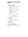
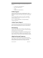
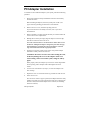
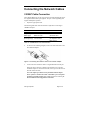
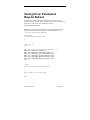
ITIpci 5100G/GF Gigabit Ethernet Host Adapters for Solaris™ Installation and User’s Guide Order Number 90-100300 Version 1.1 LSI Logic Corporation, Copyright 2000 Version 1.1 Second Printing, December, 2000 Added VLAN support Version 1.0 First Printing, August, 2000 The information in this document is subject to change without notice and should not be construed as a commitment by LSI Logic Corporation. LSI Logic Corporation assumes no responsibility for any errors that may appear in this document. LSI Logic Corporation Page 2 of 56 The, software, if any, described in this document is furnished under a license and may be used or copied only in accordance with the terms of such license. No responsibility is assumed for the use or reliability of software or equipment that is not supplied by LSI Logic Corporation or its affiliated companies. Copyright 2000 by LSI Logic Corporation. All Rights Reserved. The Reader’s Comment form at the end of this document requests your critical evaluation to assist in preparing future documentation. The LSI Logic logo design is a registered trademark of LSI Logic Corporation. The following are trademarks of IntraServer Technology, Inc.: ITIpciTM and the IntraServer logo. All other trademarks and registered trademarks are the property of their respective holders. LSI Logic Corporation Page 3 of 56 FCC Class B Notice: This device complies with Part 15 of the FCC Rules. Operation is subject to the following two conditions: 1. This device may not cause harmful interference. 2. This device must accept any interference received, including interference that may cause undesired operation. Note: This equipment has been tested and found to comply with the limits for a Class B digital device, pursuant to Part 15 of the FCC Rules. These limits are designed to provide reasonable protection against harmful interference when the equipment is operated in a commercial environment. This equipment generates, uses and can radiate radio frequency energy and, if not installed and used in accordance with the instruction manual, may cause harmful interference to radio communications. Operation of this equipment in a residential area is likely to cause harmful interference in which case the user will be required to correct the interference at his own expense. Do not make mechanical or electrical modifications to the equipment. VCCI Class 1: The equipment is Type 1 Data Processing Equipment and is intended for use in commercial and industrial districts. It has been tested and found to comply with VCCI technical requirements for the purpose of protection against electronic interference. When used in residential districts or their peripheral areas, radio, and TV receiver units may be subject to radio interference. The operation should be done in accordance with the Instruction Manual. CE Notice: The CE mark on this equipment indicates that this equipment meets or exceeds the following technical standards: EN50082-1, EN55022, EN60555-2, EN61000-4-1, EN61000-4-2, EN61000-4-3, EN61000-4-4, and EN61000-4-5. LSI Logic Corporation Page 4 of 56 FCC Declaration of Conformity The IntraServer Technology, Inc. ITIpci Gigabit Ethernet adapters, model numbers 5100G and 5100GF comply with the requirements of FCC part 15, class B as defined under paragraph 2.909 of these rules. This declaration covers product identified with ITI 5100G and 5100GF on the product label. A copy of the test report substantiating compliance is available on request from: Corporate EMC Manager IntraServer Technology, Inc. Seven October Hill Road Holliston, MA 01746 LSI Logic Corporation Page 5 of 56 TABLE OF CONTENTS INTRODUCTION ............................................................................ 8 PREFACE .......................................................................................... 8 How This Book Is Organized....................................................... 8 UNIX Commands......................................................................... 9 Typographic Conventions............................................................ 9 Shell Prompts............................................................................. 10 Contacting IntraServer Technology .......................................... 10 ABOUT THE ITI-5100G/GF ADAPTER..................................... 11 FEATURES ...................................................................................... 13 ITI-5100G and GF Models ........................................................ 13 ITI-5100G Model....................................................................... 13 ITI-5100GF Model .................................................................... 13 Key Protocols and Interfaces..................................................... 13 VLANs Support .......................................................................... 14 Jumbo Frames Support.............................................................. 14 Dual Homing ............................................................................. 14 Adaptive Interrupt Frequency.................................................... 14 Dual DMA Channels ................................................................. 15 ASIC with Embedded RISC Processor ...................................... 15 Diagnostic Support.................................................................... 15 Physical Description.................................................................. 15 INSTALLING THE ITI-5100G/GF ADAPTER .......................... 18 SYSTEM REQUIREMENTS ................................................................ 18 SAFETY PRECAUTIONS ................................................................... 19 PRE-INSTALLATION CHECKLIST ..................................................... 19 PCI ADAPTER INSTALLATION ........................................................ 20 CONNECTING THE NETWORK CABLES ............................................ 21 5100GF Cable Connection........................................................ 21 5100G Cable Connection .......................................................... 22 THE ITI-5100G/GF DRIVER SOFTWARE................................ 23 INSTALLING THE DRIVER SOFTWARE ............................................. 23 Troubleshooting: If the Driver Fails to Attach .......................... 24 CONFIGURING THE HOST FILES ...................................................... 25 CONFIGURING DRIVER PARAMETERS WITH NDD ............................ 27 Available Parameters ................................................................ 27 Checking Parameter Settings .................................................... 30 Setting Parameters .................................................................... 30 LSI Logic Corporation Page 6 of 56 LINK NEGOTIATION ....................................................................... 31 INCREASING TCP/IP PERFORMANCE ............................................. 31 SAVING DRIVER PARAMETERS BEYOND REBOOT .......................... 32 OPTIONAL CONFIGURATION ................................................. 33 VLANS .......................................................................................... 35 Overview.................................................................................... 35 Configuring VLANs ................................................................... 37 JUMBO FRAMES SUPPORT .............................................................. 40 Overview.................................................................................... 40 Configuring Jumbo Frames Support ......................................... 40 DUAL HOMING ............................................................................... 41 Overview.................................................................................... 41 Configuring Dual Homing......................................................... 42 APPENDICES................................................................................. 44 APPENDIX A................................................................................... 44 1000BASE-SX Link Characteristics .......................................... 44 10/100/1000BASE-T Cable Specifications ................................ 44 Performance Specifications....................................................... 44 Physical Characteristics............................................................ 44 Power Requirements.................................................................. 45 Environmental Specifications .................................................... 45 APPENDIX B................................................................................... 46 Ethernet Connector ................................................................... 46 Network Cabling Requirements................................................. 46 APPENDIX C................................................................................... 47 Glossary of Terms...................................................................... 47 List of Figures............................................................................ 49 List of Tables ............................................................................. 49 APPENDIX D................................................................................... 50 Software License........................................................................ 50 End-User License Agreement for Software ...................................... 50 PRODUCT WARRANTY ................................................................... 54 READER’S COMMENTS ................................................................... 56 LSI Logic Corporation Page 7 of 56 _________________________ Introduction Preface This guide describes how to install and use the following IntraServer Technology ITI-5100G/GF adapters in the Solaris operating environment: •= PCI (Peripheral Component Interconnect) ITI-5100G Gigabit Ethernet for Copper adapter •= PCI (Peripheral Component Interconnect) ITI-5100GF Gigabit Ethernet for Fiber adapter The procedures in this guide assume that you are a system or network administrator experienced in installing similar hardware in the Solaris environment. How This Book Is Organized This book is organized as follows: “About the ITI-5100G/GF Adapter,” describes the features of the ITI-5100G/GF adapter, and lists the hardware and software requirements for its installation and use. “Installing the ITI-5100G/GF Adapter,” explains how to physically install the adapter in your system. “The ITI-5100G/GF driver software,” explains how to install and configure the Gigabit Ethernet adapter software in the Solaris environment. “Optional Configuration,” explains how to configure the adapter for use with VLANs, Jumbo Frames, and Dual Homing. “Appendix,” provides adapter hardware, connector and cabling specifications, glossary and lists of figures and tables. LSI Logic Corporation Page 8 of 56 UNIX Commands This document may not include all necessary software commands or procedures. Instead, it may name software tasks and refer you to operating system documentation or the handbook that was shipped with your workstation. You might need to use supplemental documentation for the following types of information: •= Shutting down the system •= Booting the system •= Configuring devices •= Other basic software procedures Typographic Conventions Table 1 describes the meanings of the various typographic styles used in this book. Typographic Conventions Typeface or Symbol AaBbCc123 AaBbCc123 AaBbCc123 [] Meaning Example This type is used for names of View the commands, files, and directories used readme.txt file. within the text. It also depicts on-screen computer output and prompts. This bold type appears in command examples. It shows text that must be typed in exactly as shown. This italicized type appears in command examples as a parameter placeholder. Replace the indicated text with the appropriate real name or value when using the command. >> Main# >> Main# sys To establish a Telnet session, enter: host# telnet IPaddress This also shows book titles, special Read your User’s Guide thoroughly. terms, or words to be emphasized. Command items shown inside brackets are optional and can be used host# ls [ -a ] or excluded as the situation demands. Do not type the brackets. Table 1: Typographic Conventions LSI Logic Corporation Page 9 of 56 Shell Prompts Shell Prompts Shell C shell C shell superuser Bourne shell and Korn shell Bourne shell and Korn shell superuser Prompt machine_name % machine_name # $ # Table 2: Shell Prompts Contacting IntraServer Technology Use the following information to access IntraServer Technology support and sales. •= URL for IntraServer Technology Online: http://www.intraserver.com This website includes product information, software updates and release notes. The website also includes access to IntraServer Technology Customer Support for accounts under warranty or that are covered by a maintenance contract. •= E-mail access: [email protected] E-mail access to IntraServer Technology Customer Support is available to accounts that are under warranty or covered by a maintenance contract. •= Telephone access to IntraServer Technology Customer Support: 1-508-429-0425 Extension 2 Telephone access to IntraServer Technology Customer Support is available to accounts that are under warranty or covered by a maintenance contract. Normal business hours are 8 a.m. to 6 p.m. Eastern Standard Time. •= Telephone access to IntraServer Technology Sales: 1-508-429-0425 Extension 1 Telephone access is available for information regarding product sales and upgrades. LSI Logic Corporation Page 10 of 56 ________________________1 About the ITI-5100G/GF Adapter Figure 1: IntraServer Technology ITI-5100GF Gigibit Ethernet Fiber Interface Adapter The ITI-5100GF adapter connects your PCI compliant server or workstation to a Gigabit Ethernet network. The adapter incorporates a technology that transfers data at a rate of one gigabit per second, 10 times the rate of a Fast Ethernet adapter. ITI-5100GF offers a Duplex SC fiber-optic connection. LSI Logic Corporation Page 11 of 56 Figure 2: IntraServer Technology ITI-5100G Gigibit Ethernet Copper 10/100/100Base-T Interface Adapter The ITI-5100G adapter connects your PCI compliant server or workstation to a Gigabit Ethernet network. The adapter incorporates a technology that transfers data at a rate of one gigabit per second, 10 times the rate of a Fast Ethernet adapter. ITI-5100G offers a Twisted Pair Copper interface, which is compatible with existing building (CAT-5) wiring systems. AutoSense speed selection allows operation at speeds of 10, 100 and 1000Mbits/sec, making the ITI-5100G ideal for upgrading existing networks to Gigabit Ethernet. The ITI-5100G/GF adapter targets the increased congestion experienced at the backbone and server by today's networks, while providing a future upgrade path for high-end workstations that require more bandwidth than Fast Ethernet can provide. Included with your adapter is the following: •= Anti-static bag (used for protecting the adapter when stored or shipped). Keep the adapter in its packaging until ready for installation. •= ITI-5100G/GF Gigibit Ethernet Adapter Software Distribution media containing ITI-5100G/GF adapter driver software and documentation Inform your network supplier of any missing or damaged items. If you need to return the adapter, you must pack it in the original (or equivalent) packing material or the warranty will be voided. LSI Logic Corporation Page 12 of 56 Features Following is a list of the Gigabit Ethernet PCI adapter features: ITI-5100G and GF Models •= Full-duplex Gigabit Ethernet interface (IEEE P802.3-1999) •= Jumbo Frame support (optional 9,000 byte frames for serverto-server traffic) •= Standard Ethernet frame size (up to 1518 bytes) •= Dual Homing for automatic failover if a port, switch, or adapter is down •= VLANs: up to 64 VLANs per adapter using IEEE 802.1Q1998 tagging •= Adaptive interrupt frequency (maximizes network throughput; adapts to traffic load) •= Dual DMA channels •= 33/66 MHz, 32-bit or 64-bit PCI bus master with adaptive DMA •= Universal dual voltage signaling (3.3V and 5V) •= PCI Local Bus Rev 2.1 compliant (6.8"x 4.2") •= ASIC with on-chip MAC and dual RISC processors •= Status LEDs ITI-5100G Model •= CAT-5 compatible twisted pair Ethernet Connector •= Interoperability with existing Ethernet and Fast Ethernet Equipment ITI-5100GF Model •= Duplex SC fiber-optic connector Key Protocols and Interfaces ITI-5100G/GF adapters are interoperable with existing Ethernet equipment assuming standard Ethernet minimum and maximum frame size (64 to 1518 LSI Logic Corporation Page 13 of 56 bytes), frame format, and compliance with the following standards and protocols: •= Logical Link Control (IEEE 802.2) •= Flow Control (IEEE 802.3x) •= SNMP •= Gigabit Ethernet (IEEE P802.3z) VLANs Support Virtual Local Area Networks ( VLANs ) are commonly used to split up groups of network users into manageable broadcast domains, to create logical segmentation of workgroups, and to enforce security policies among logical segments. Each ITI-5100G/GF adapter supports up to 64 VLANs. With multiple VLANs on an adapter, a server with a single adapter can have a logical presence on multiple IP subnets. Refer to the “Optional Configuration,” section of this manual for configuration information. Jumbo Frames Support To reduce host frame processing overhead, the ITI-5100G/GF adapter and Gigabit switches that support jumbo frames, can receive and transmit frames that are larger than the maximum frame size allowed on normal Ethernet. Dual Homing Server switching networks require the capability to employ resiliency and redundancy similar to FDDI network environments. ITI-5100G/GF adapters provide the Ethernet user with this capability. For dual homing support, you must install two ITI-5100G/GFs in the same host system. The adapters are configured to provide a hot-standby failover service. The switches must be configured to support Spanning Tree on both Gigabit Ethernet ports to support the ITI-5100G/GF Dual Homing capability. Adaptive Interrupt Frequency The adapter driver intelligently adjusts host interrupt frequency based on traffic conditions, in order to increase overall application throughput. In light traffic, the adapter driver interrupts the host for each received packet, minimizing latency. When traffic is heavy, the adapter issues one host LSI Logic Corporation Page 14 of 56 interrupt for multiple, back-to-back incoming packets, preserving host CPU cycles. Dual DMA Channels The PCI interface on the ITI-5100G/GF adapter contains two independent DMA channels for simultaneous read and write operations. ASIC with Embedded RISC Processor The core control for the ITI-5100G/GF adapter resides in a tightly integrated, high-performance ASIC. The ASIC includes dual RISC processors. This provides the flexibility to add new features to the card and adapt it to future network requirements via software download. This also enables the adapter drivers to exploit the built-in host off-load functions on the adapter as host operating systems are enhanced to take advantage of these functions. Diagnostic Support An ITI-5100G/GF adapter RISC CPU runs on-board diagnostics at power-up. Physical Description Figure 3: ITI-5100GF adapter faceplate The faceplate of the ITI-5100GF adapter has one 1000Base-SX fiber-optic connector for connecting the adapter to a Gigabit Ethernet segment. There are also two LEDs: one to indicate link status and one for data transfer status. Once the adapter hardware and its driver software have been properly installed on your system, the LEDs will signal the following adapter states: LED Data Link ITI-5100GF Port LED Activity State Description Blinking Data detected on the port. On Data detected on the port. Off No data detected on the port. Blinking slowly Port has been disabled by software. LSI Logic Corporation Page 15 of 56 On Off Good link. No link; possible bad cable, bad connector, missing or improperly installed driver software, or configuration mismatch. Table 3: ITI-5100GF LED Status Indicators LSI Logic Corporation Page 16 of 56 DATA 1000 100 10 10/100/1000 BASE-T Figure 4: ITI-5100G adapter faceplate The faceplate of the ITI-5100G adapter has one 10/100/1000Base-T twisted pair copper (CAT-5) connector for connecting the adapter to a Gigabit Ethernet segment. The adapter will also operate in an existing 10/100 Ethernet environment. LED Data 1000 100 10 State Blinking On Off On Off On Off On Off ITI-5100G Port LED Activity Description Data detected on the port. Data detected on the port. No data detected on the port. Good link. at 1000Mb/sec No link; possible bad cable, bad connector, missing or improperly installed driver software, or configuration mismatch. Good link. at 100Mb/sec No link; possible bad cable, bad connector, missing or improperly installed driver software, or configuration mismatch. Good link. at 10Mb/sec No link; possible bad cable, bad connector, missing or improperly installed driver software, or configuration mismatch. Table 4: ITI-5100G LED Status Indicators LSI Logic Corporation Page 17 of 56 ________________________2 Installing the ITI-5100G/GF Adapter The following instructions apply to installing the ITI-5100G/GF adapter in most servers. Refer to the manuals that were supplied with your server for details about performing these tasks on your particular system. System Requirements Before installing the ITI-5100G/GF adapter, make sure your system meets the requirements listed in the following table: Hardware and Software Requirements Category Requirements Hardware PCI All PCI based SunTM Systems Firmware OpenBootTM PROM version 3.0 or greater. Software Operating System Solaris 2.6 and later. ITI-5100G/GF 32-bit and 64-bit adapter driver Adapter Software software for Solaris. (see www.intraserver.com for driver updates) Table 5: Hardware and Software Requirements LSI Logic Corporation Page 18 of 56 Safety Precautions CAUTION: •= •= •= •= •= The adapter is being installed in a server that operates with voltages that can be lethal. Before you remove the cover of your server, you must observe the following precautions to protect yourself and to prevent damage to the system components. Remove any metallic objects or jewelry from your hands and wrists. Make sure to use only insulated or non-conducting tools. Installation or removal of adapters must be performed in a static-free environment. The use of a properly grounded wrist strap or other personal anti-static devices and an anti-static mat is strongly recommended. Verify that the server is powered OFF before accessing internal components. Pre-Installation Checklist 1. Check that your server meets the hardware and software requirements listed in Table 5: Hardware and Software Requirements. 2. Review the information in the readme file on the ITI-5100G/GF Software Distribution media for important information not available at the time this manual was printed. Note: If you acquired the adapter software on a floppy disk or from the IntraServer Technology support website, please check the appropriate source for the most recent information. 3. If your system is active, execute proper shutdown. 4. When system shutdown is complete, power OFF your system. 5. Holding the adapter card by the edges, remove it from its shipping package it and place it on an anti-static surface. 6. Check the adapter for visible signs of damage, particularly on the card's edge connector. Never attempt to install any damaged adapter. If the adapter is damaged, report it to your IntraServer Technology Customer Support Representative. For more information, see Contacting IntraServer Technology. LSI Logic Corporation Page 19 of 56 PCI Adapter Installation To install a PCI ITI-5100G/GF adapter in your system, perform the following procedure. 1. Observe all precautions and pre-installation instructions in the Safety Precautions section. Before installing the adapter, ensure the system power is OFF , and proper electrical grounding procedures have been followed. 2. Remove the server cover, and select any empty PCI slot. If you do not know how to identify a PCI slot, refer to your server documentation. 3. Remove the blank cover-plate from the slot that you selected. Retain the screw so that it can be replaced later. 4. Holding the PCI card by the edges, align the adapter's connector edge with the PCI connector dock in the server. Note: The connector dock in a 32-bit PCI slot is shorter than in a 64bit PCI slot. Although the adapter is designed to fit in either slot type, when installed in a 32-bit PCI slot, part of the adapter's connector edge will remain undocked. This is perfectly normal. 5. Applying even pressure at both corners of the card, push the adapter card until it is firmly seated in the PCI slot. CAUTION: Do not use excessive force when seating the card, as this may damage the server or the adapter. If the card resists seating, remove it from the system, realign it, and try again. When properly seated, the adapter's port connectors will be aligned with the slot opening, and its faceplate will be flush against the server chassis. 6. Use the screw removed above (in Step 3) to secure the adapter in the PCI card cage. 7. Replace the server cover and disconnect any personal anti-static devices. 8. Power the server on. Once the server returns to proper operation, the adapter hardware is fully installed. You must next connect the network cables (see Connecting the Network Cables) and install the adapter driver software (see Installing the Driver Software). LSI Logic Corporation Page 20 of 56 Connecting the Network Cables 5100GF Cable Connection The 5100GF adapter has one SC-type connector used for attaching the server to a Gigabit Ethernet fiber-optic segment. The port is auto-negotiating and supports full-duplex operation. 1. Prepare an appropriate cable. The following table lists cable characteristics required for connecting to 1000Base-SX ports: 1000BASE-SX Link Characteristics 62.5 Micron 50 Micron Shortwave (850 nanometers) Shortwave (850 nm) Multimode fiber Multimode fiber 2 to 550 meters Operating Range 2 to 260 meters (in compliance with IEEE 802.3z) Description Frequency Cable Type Table 6: 1000BASE-SX Link Characteristics 2. As shown in the following diagram, connect one end of the cable to the ITI-5100G/GF adapter. Figure 5: Connecting the network cable to the 5100GF adapter 3. Connect the other end of the cable to a Gigabit Ethernet network port. Attach the cable connector so that the TX (transmit) port on the ITI5100G/GF adapter is connected to the RX (receive) port of the device at the other end of the cable. Note: The adapter port LEDs are not functional until the adapter driver software is installed. See Table 3 and Table 4 for a description of adapter port LED operation. See Installing the Driver Software for driver installation and configuration instructions. LSI Logic Corporation Page 21 of 56 5100G Cable Connection The 5100G adapter has one RJ-45 connector used for attaching the server to an Ethernet twisted pair copper segment. The port is auto-negotiating and supports full-duplex operation. 1. Prepare an appropriate cable. The following table lists cable characteristics required for connecting to 10/100/100 Base-T ports: 10/100/1000BASE-T Cable Specifications Port Type Connector 10Base-T RJ-45 100/1000Base-T RJ-45 Maximum Distance Cat. 3, 4 or 5 UTP 100 Meters Cat. 5 UTP 100 Meters Media Table 7: 10/100/1000BASE-T Cable Specifications 2. Connect one end of the cable to the ITI-5100G/GF adapter. 3. Connect the other end of the cable to a Gigabit Ethernet network port. Note: The adapter port LEDs are not functional (they will not reflect port link or data status) until the adapter driver software is installed. LSI Logic Corporation Page 22 of 56 ________________________3 The ITI-5100G/GF Driver Software A network device driver must be installed before the ITI-5100G/GF adapter can be used with your systems. This chapter describes how to preform the following tasks: Install the driver software in the Solaris environment Configure the host files Configure driver parameters using the ndd utility Installing the Driver Software Note: The ITI-5100G/GF adapter must be physically installed in your server prior to installing the driver software. See “Installing the ITI5100G-GF Hardware,” for details. To install the adapter software for Solaris, perform the following procedure: 1. Become superuser (root). 2. Note the revision level of the Software Distribution Media included with your IntraServer Technology adapter. The revision level is stamped on the Software Distribution Media label and is used in the commands below. Place the Software Distribution Media into the CD-ROM drive. Mount the CD-ROM on a local directory. If the Volume manager (vold) is running on your machine, when the ITI-5100G/GF CD-ROM is loaded into the drive, it is mounted automatically under /cdrom/cdrom0 #volcheck Access the package directory by entering the following: # cd /cdrom/cdrom0 LSI Logic Corporation Page 23 of 56 At the prompt, type the pkgadd command: # pkgadd -d . The screen displays a list of packages available for installation: The following packages are available: 1 ITIalt IntraServer/LSI Logic 32/64-bit Gigabit Ethernet Adapter (sparc)Kit Version x.x Select package(s) you wish to process (or `all' to process all packages). (default: all) [?, ??, q] Type the number for the ITIalt driver and press Return. The pkgadd command starts the installation script. Do not select the default: all option to install "all" drivers. Install only the driver appropriate for your system: ITIalt . Respond to prompts in the script. pkgadd keeps cycling through its script once it has started. Therefore you must quit ( q ) the program the second time the list of packages is displayed. When you have finished loading the software, eject the CD-ROM by entering the following commands: # cd / # eject cdrom Troubleshooting: If the Driver Fails to Attach If the adapter is not installed, you will see the following message when you run pkgadd : drvconfig: Driver (alt) failed to attach Warning: Driver (alt) successfully added to system but failed to attach pkgadd: ERROR: postinstall script did not complete successfully If this happens, halt your machine using the following commands: LSI Logic Corporation Page 24 of 56 # sync # sync # halt Then, at the ok prompt, use the following command to list the system devices: ok show-devs ITI-5100G/GF adapter output will be displayed. Sample PCI examples are shown on the next page. For PCI systems, " ethernet@1 " identifies the PCI ITI-5100G/GF adapter: /SUNW,ffb@1e,0 /SUNW,UltraSPARC-II@0,0 /pci@1f,2000 /pci@1f,4000 /counter-timer@1f,1c00 /virtual-memory /memory@0,60000000 /aliases /options /openprom /chosen /packages /pci@1f,2000/ethernet@1 /pci@1f,4000/scsi@3 /pci@1f,4000/network@1,1 /pci@1f,4000/ebus@1 /pci@1f,4000/scsi@3/tape /pci@1f,4000/scsi@3/disk /pci@1f,4000/ebus@1/SUNW,CS4231@14,200000 .... If the appropriate ITI-5100G/GF device is not listed, check that the adapter is installed and properly seated. Then restart the system and re-install the adapter software. Configuring the Host Files Once the ITI-5100G/GF adapter software is installed on your system, it must be configured. To ensure proper adapter performance, configure the host files and driver parameters as described in the following sections. LSI Logic Corporation Page 25 of 56 Note: If any adapter card is moved from one slot to another, the alt instance values in the /etc/path_to_inst file will be incorrect. Correct the instance values before making any adapter configuration changes. See your Solaris manuals for details on setting instance values. 1. •= Each adapter must be assigned a host name and an IP address. If you are not using multiple VLANs, perform the steps below when configuring the host name and IP address for your adapter. •= If VLANs are to be used, any specific adapter may have one host name and IP address for each VLAN. If you will be using VLANs on the network, see the Configuring VLANs section of this manual. Create the /etc/hostname.alt <num> file(s) on the server. There can be up to four adapters per server. Create one /etc/hostname.alt <num> file for each adapter. The number <num> in the filename is determined as follows: Adapter First Second Third Fourth Hostname Numbering Hostname /etc/hostname.alt0 /etc/hostname.alt1 /etc/hostname.alt2 /etc/hostname.alt3 For example, the first adapter in the server requires a file named /etc/hostname.alt0 and the second adapter requires a file named /etc/hostname.alt1 . 2. Place the appropriate adapter host name into the hostname.alt <num> file(s). The /etc/hostname.alt <num> file must contain the appropriate host name for the adapter. The host name should be different from that of any other interface. For example, /etc/hostname.alt0 and /etc/hostname.alt1 cannot share the same host name. The following example depicts the host name files required for a machine called iti , with ITI-5100G/GF adapters known as iti-1 , iti-2 , iti-3 , and iti-4 on the networks created for alt0 , alt1 , alt2 , and alt3 . LSI Logic Corporation Page 26 of 56 iti # iti-1 iti # iti-2 iti # iti-3 iti # iti-4 cat /etc/hostname.alt0 cat /etc/hostname.alt1 cat /etc/hostname.alt2 cat /etc/hostname.alt3 3. For each host name, enter the appropriate IP address in the /etc/hosts file. 4. Reboot the system. If you make changes and put the system into service before rebooting, you may experience configuration problems. Perform this command to reboot the system: # reboot -- -r Configuring Driver Parameters with ndd The ndd (1M) utility is useful for changing configuration parameters for the adapter. Alternately, adapter parameters can be changed by manually editing the configuration files. This section describes the ndd utility in detail. Note: Any changes made with ndd are temporary and will be lost when you reboot the system. To make configuration changes survive the reboot process, you will need to store driver settings in the /etc/rc2.d/S99itialt file (see Saving Driver Parameters Beyond Reboot). Available Parameters To view parameters that you can set using the ndd command, type: # ndd /dev/alt '?' The system returns the following: stat_ticks (read and write) send_max_coalesced_bds (read and write) send_coal_ticks (read and write) recv_max_coalesced_bds (read and write) LSI Logic Corporation Page 27 of 56 recv_coal_ticks (read and write) nic_tracing (read and write) link_negotiation (read and write) dump_nic (read and write) jumbo (read and write) vlan? (read and write) vlan_tag (read and write) vlan_tag_id (read and write) redund? (read and write) redund (read and write) fdr_filter (read and write) rx_flow_control (read and write) tx_flow_control (read and write) hybrid_len (read and write) shared_rupt (read and write) snap (read and write) instance (read and write) LSI Logic Corporation Page 28 of 56 The following table describes the driver parameters available through ndd . Adapter Driver Parameters Meaning Minimum number of 1 sec ticks between statistics stat_ticks updates. 0 (off) is the minimum, and 100,000 is the default. There is no maximum. Number of sends before a send complete event is set. 1 is the minimum, 127 is the maximum, and 60 send_max_coalesced_bds is the default. WARNING: Setting this to an improper value can result in driver performance degradation or failure. send_coal_ticks (Do not use; value is set by startup file) Maximum number of receives that can be bundled into an event. 1 is the minimum, 511 is the recv_max_coalesced_bds maximum, and 6 is the default. WARNING: Setting this to an improper value can result in degraded performance. nic_tracing (Not currently used) Used to set IEEE 802.3z Link Negotiation to auto link_negotiation or off. Use a value of 0 for off, or 1 for auto. The default is 1 (auto). dump_nic (Do not use; reserved for debugging) jumbo (Do not use; value is set by startup file) vlan? (Do not use; value is set by startup file) vlan_tag (Do not use; value is set by startup file) vlan_tag_id (Do not use; value is set by startup file) redund? (Do not use; value is set by startup file) redund (Do not use; value is set by startup file) Full-Duplex Repeater Filter. For older adapters (Model 710002), turn this on if the adapter is fdr_filter attached to a Full-Duplex Repeater. Use a value of 0 for off, or 1 for on. The default is 0 (off). If link negotiation is on, a value of 1 allows the adapter to negotiate 802.3x receive flow control with the device at the other end of the link. If rx_flow_control 802.3x flow control is supported by the other device, receive pause packets will be respected. A value of 0 disables receive flow control. The default is 1 (on). Parameter LSI Logic Corporation Page 29 of 56 Parameter tx_flow_control hybrid_len shared_rupt snap instance Adapter Driver Parameters Meaning If link negotiation is on, a value of 1 allows the adapter to negotiate 802.3x transmit flow control with the device at the other end of the link. If 802.3x flow control is supported by the other device, transmit pause packets will be respected. A value of 0 disables transmit flow control. The default is 0 (off). (Do not use; value is set by startup file) (Do not use; value is set by startup file) (Do not use; value is set by startup file) Used to set the device number from which the previous data is extracted. This value can range from 0 to the number of adapters installed in the system. The default is 0. Table 8: Adapter Driver Parameters Checking Parameter Settings To check a current parameter setting, use the following command: # ndd /dev/alt <parameter_name> Setting Parameters Follow this procedure to set parameters using the ndd utility: 1. Check the /etc/path_to_inst file for the instance associated with particular devices. 2. Specify the instance for the adapter you wish to configure: # ndd -set /dev/alt instance <instance#> Any subsequent ndd configuration commands will act on the adapter with the selected instance. The adapter remains selected until you specify a different instance. 3. Specify the configuration command using the following format: # ndd -set /dev/alt <parameter> <value> A list of valid parameters and values can be found in Available Parameters. LSI Logic Corporation Page 30 of 56 Note: Any changes made with ndd will be lost when you reboot the system. To make configuration changes survive reboot, store driver settings in the /etc/rc2.d/S99itialt file (see Saving Driver Parameters Beyond Reboot). Link Negotiation The default configuration for link negotiation of the Gigabit Ethernet link is auto . With this setting the ITI-5100G/GF adapter will use IEEE 802.31998 auto negotiation. If you are connecting the adapter to Gigabit Ethernet equipment that does not support auto negotiation, or if there is a problem establishing a link between the two devices, auto negotiation can be turned off (see Available Parameters). Increasing TCP/IP Performance The TCP/IP performance of the ITI-5100G/GF PCI adapter can be increased by changing the TCP/IP ndd values. This can be done with the ndd (1M) utility, as described below. Enter the following ndd commands to increase TCP/IP performance: # # # # ndd ndd ndd ndd -set -set -set -set /dev/tcp /dev/tcp /dev/udp /dev/udp tcp_recv_hiwat tcp_xmit_hiwat udp_recv_hiwat udp_xmit_hiwat 65535 65535 65535 65535 To avoid losing these settings when reboot occurs, add your ndd parameter settings to the start-up file as described in the following section, Saving Driver Parameters Beyond Reboot. LSI Logic Corporation Page 31 of 56 Saving Driver Parameters Beyond Reboot Any parameter changes made using ndd will be lost the next time your system is rebooted. To keep changes through reboot, parameter settings must be placed in a start-up file with the following filename: /etc/rc2.d/S99itialt Example: If you need to adjust adapter 2 to turn Link Negotiation off and increase the TCP/IP values, you could place the following lines in the /etc/rc2.d/S99itialt start-up file: #!/sbin/sh # local kernel modification # case "$1" in 'start') echo "Setting local kernel parameters...\c" ndd -set /dev/alt instance 2 ndd -set /dev/alt link_negotiation 0 ndd -set /dev/tcp tcp_recv_hiwat 65535 ndd -set /dev/tcp tcp_xmit_hiwat 65535 ndd -set /dev/udp udp_xmit_hiwat 65535 ndd -set /dev/udp udp_recv_hiwat 65535 echo " " ;; 'stop') echo "$0: No parameters changed." ;; *) echo "Usage: $0 {start|stop}" ;; esac LSI Logic Corporation Page 32 of 56 ________________________4 Optional Configuration Your IntraServer Technology ITI-5100G/GF adapter can be configured to support the following options: •= VLANs: Virtual Local Area Networks (VLANs) are commonly used to split up groups of network users into manageable broadcast domains, to create logical segmentation of workgroups, and to enforce security policies among each logical segment. Up to 64 VLANs can be defined for each ITI-5100G/GF adapter on your server •= Jumbo Frames: Standard Ethernet frames are 1,500 bytes long. When sending Ethernet traffic at Gigabit speeds, a considerable portion of the bandwidth is consumed by the overhead of handling a multitude of small packets. ITI5100G/GF adapters support Ethernet frames of 9,000 bytes. Host CPU utilization is significantly reduced and network throughput is enhanced when enabling Jumbo Frames between servers that have ITI-5100G/GF adapters and switches that support Jumbo Frames. •= Dual Homing: Two ITI-5100G/GF adapters on a server can be paired for redundant operation through the use of the Dual Homing feature. If traffic on a primary connection is lost due to the failure of the adapter, cable, switch port, or switch (when the dual adapters are attached to separate switches), the secondary adapter becomes active and assumes the MAC and IP address of the primary adapter. Network sessions should be maintained after the switchover, causing minimum impact to network traffic. This chapter describes these options in detail, with configuration instructions and examples. If your network does not require VLANs, Jumbo Frames, or Dual Homing, you need only configure the adapter to support the default configuration, as described in “The ITI-5100G/GF Driver Software”. LSI Logic Corporation Page 33 of 56 Note: If you modify any of the optional configuration parameters (VLANs, Jumbo Frame, or Dual Homing), you must reboot the system before the changes will take effect. If you make changes and do not reboot, you may experience configuration problems. LSI Logic Corporation Page 34 of 56 VLANs VLANs allow you to split your physical LAN into logical subparts, providing an essential tool for increasing the efficiency and flexibility of your network. Overview Each defined VLAN behaves as its own separate network, with its traffic and broadcasts isolated from the other VLANs to increase bandwidth efficiency within each logical group. One example of how VLANs can be used to segment a LAN is when isolating different types of network traffic. If you wanted to utilize Jumbo Frames on a portion of your LAN, you could configure one VLAN for devices that support Jumbo Frames, and a separate VLAN for devices supporting only standard frames. By implementing VLANs, you could segregate the different frame types from each other without reorganizing your LAN into separate physical subnets. Although VLANs are commonly used to create individual broadcast domains and/or separate IP subnets, it is sometimes useful for a server to have a presence on more than one VLAN simultaneously. Alteon WebSystems switches and ITI5100G/GF adapters support multiple VLANs on a per-port or per-interface basis, allowing very flexible network configurations. See Figure 6 for an example of servers supporting multiple VLANs with Tagging. VLAN #1 Accounting Server (VLAN #3) VLAN #2 VLAN #3 Main Server (All VLANs) ITI5100G Gigabit VLAN Tagged Shared Media Segment PC #1 Software Dept. (VLAN #2) PC #2 Software Dept. (VLAN #2) PC #3 Engineering (VLAN #1) PC #4 Accounting (VLAN #3) PC #5 Engineering/Software (VLAN #1 & #2) ITI5100G Gigabit VLAN Tagged Figure 6: Servers Supporting Multiple VLANs LSI Logic Corporation Page 35 of 56 In the example network shown in Figure 6, the physical LAN consists of a switch, two servers, and five clients. The LAN is logically organized into three different VLANs, each representing a different IP subnet. The features of this network are described in the following table. Example VLAN Network Topology Description An IP subnet consisting of the Main Server, PC #3, and PC #5. VLAN #1 This subnet represents an engineering group. Includes the Main Server, PCs #1 and #2 via shared media VLAN #2 segment, and PC #5. This VLAN is a software development group. Includes the Main Server, the Accounting Server and PC #4. VLAN #3 This VLAN is an accounting group. A high-use server that needs to be accessed from all VLANs and IP subnets. The Main Server has an ITI5100G adapter installed. All three IP subnets are accessed via the single physical adapter interface. The server is attached to an Alteon WebSystems switch Gigabit Ethernet port, which is Main Server configured for VLANs #1, #2, and #3. Both the adapter and the connected switch port have tagging turned on. Because of the tagging VLAN capabilities of both devices, the server is able to communicate on all three IP subnets in this network, but continues to maintain broadcast separation between all of them. Available to VLAN #3 only. The Accounting Server is Accounting isolated from all traffic on VLANs #1 and #2. The switch port Server connected to the server has tagging turned off. Attached to a shared media hub that is then connected to the switch. PCs #1 and #2 belong to VLAN #2 only, and are PCs #1 and #2 logically in the same IP subnet as the Main Server and PC #5. The switch port connected to this segment has tagging turned off. A member of VLAN #1, PC #3 can communicate only with PC #3 the Main Server and PC #5. Tagging is not enabled on PC #3's switch port. A member of VLAN #3, PC #4 can only communicate with PC #4 the servers. Tagging is not enabled on PC #4's switch port. A member of both VLANs #1 and #2, PC #5 has an ITI5100G adapter installed. It is connected to switch port #10. Both the PC #5 adapter and the switch port are configured for VLANs #1 and #2 and have tagging enabled. Component Table 9: Example VLAN Network Topology LSI Logic Corporation Page 36 of 56 VLAN tagging is only required to be enabled on switch ports that create trunk links to other VLAN capable switches, or on ports connected to tag-capable end-stations, such as servers or workstations with ITI5100G/GF adapters. Configuring VLANs By default, Alteon WebSystems switches have a single VLAN configured for every port, which groups all ports into the same broadcast domain, just as if there were no VLANs at all. This default VLAN has an 802.1Q-1998 VLAN identification number of [1], with VLAN tagging for the switch port turned off. If you are using a VLAN capable switch from another manufacturer, consult the documentation for your switch before continuing. To configure VLANs, perform the following procedure: Note: If you configure a VLAN for an adapter, all traffic sent or received by that adapter must be in VLANs. 1. Create the /etc/hostname.alt file(s) on the server. There can be up to four adapters per server, and up to 64 VLANs defined per adapter. One /etc/hostname.alt <num> file must be created for each VLAN that will be configured for each adapter on the server. Create files using the following naming format: /etc/hostname.alt <num> For each file, the number <num> in the filename is determined according to the table below. For example, the first adapter in the server requires a file named /etc/hostname.alt0 for its first VLAN, and a file named /etc/hostname.alt100 for its second VLAN. Up to 64 VLANs First Adapter Second Adapter Third Adapter Fourth Adapter 1 /etc/hostname /etc/hostname /etc/hostname /etc/hostname .alt0 .alt1 .alt2 .alt3 2 /etc/hostname /etc/hostname /etc/hostname /etc/hostname .alt100 .alt101 .alt102 .alt103 3 /etc/hostname /etc/hostname /etc/hostname /etc/hostname .alt200 .alt201 .alt202 .alt203 LSI Logic Corporation Page 37 of 56 ... 64 /etc/hostname /etc/hostname /etc/hostname /etc/hostname .alt6300 .alt6301 .alt6302 .alt6303 Table 10: Creating the /etc/hostname.alt<num> files 2. Place the appropriate adapter host name into the /etc/hostname.alt file(s). The /etc/hostname.alt <num> file must contain the appropriate adapter host name. The host name should be different from the host name of any other interface. For example, /etc/hostname.alt0 and /etc/hostname.alt100 cannot share the same host name. The following example depicts the host name files required for a machine called iti , with one ITI5100G/GF adapter with four VLANs: iti # cat /etc/hostname.alt0 iti-1 iti # cat /etc/hostname.alt100 iti-1100 iti # cat /etc/hostname.alt200 iti-1200 iti # cat /etc/hostname.alt300 iti-1300 3. For each host name, enter the appropriate IP address in the /etc/hosts file. 4. Create the /etc/vlan.alt <num> file(s). One corresponding /etc/vlan.alt <num> file is needed for each /etc/hostname.alt <num> file created in the previous steps (one for each VLAN being configured for each adapter on the server). Create files using the following naming format: /etc/vlan.alt <num> For each file, the number <num> in the filename is determined according to the table below. For example, the first adapter requires a file named /etc/vlan.alt0 for its first VLAN, and a file named /etc/vlan.alt100 for its second VLAN. LSI Logic Corporation Page 38 of 56 Up to 64 VLANs First Adapter Second Adapter Third Adapter Fourth Adapter 1 /etc/vlan .alt0 /etc/vlan .alt1 /etc/vlan .alt2 /etc/vlan .alt3 2 /etc/vlan .alt100 /etc/vlan .alt101 /etc/vlan .alt102 /etc/vlan .alt103 3 /etc/vlan .alt200 /etc/vlan .alt201 /etc/vlan .alt202 /etc/vlan .alt203 /etc/vlan .alt6300 /etc/vlan .alt6301 /etc/vlan .alt6302 /etc/vlan .alt6303 ... 64 Table 11: Creating the /etc/vlan.alt<num> files 5. Place the appropriate VLAN ID tag into the vlan.alt <num> file(s). Each VLAN must be assigned a unique identification number. Even though the maximum number of VLANs that can be configured on each adapter is 64, any particular VLAN can be assigned an identification number between 1 and 4094. The VLAN tagging format follows the guidance provided in IEEE 802.1Q-1998. The VLAN identifier numbers must be placed into each appropriate vlan.alt <num > file to which the adapter is a member. Example: Consider a server with a single adapter. The server is a member of two VLANs, with VLAN identifiers 383 and 777. The contents of the first file, /etc/vlan.alt0 , would be "383" and the contents of the second file, /etc/vlan.alt100 , would be "777". Use your regular text editor to put the VLAN identifier number into the appropriate vlan.alt <num> file. Be certain that there are no spaces, blank lines, or extra characters. The identifier can be entered in decimal (e.g. 383), octal (e.g. 0577), or hexadecimal (e.g. 0x17F) format. If you are finished with all optional configurations, reboot the system. Changes to the optional configuration parameters (VLAN, Jumbo Frame, or Dual Homing) do not take effect until you reboot the system. If you will be making changes to the other optional parameters during your configuration session, you should wait to reboot until those changes are complete. If you modify parameters and put the system into service before rebooting, you may experience configuration problems. Perform this command to reboot the system: LSI Logic Corporation Page 39 of 56 # reboot -- -r Verify the configuration changes. Enter the following command and verify that the appropriate VLANs are present: # ifconfig -a Jumbo Frames Support ITI-5100G/GF adapters support Jumbo Frames--frames of up to 9,000 bytes that are sent between servers that have ITI-5100G/GF adapters and switches that support Jumbo Frames. Host CPU utilization is significantly reduced and network throughput is enhanced by sending 9,000 byte frames rather than the standard 1,500 byte Ethernet frames. Overview A single ITI-5100G/GF adapter on a server can support standard Ethernet frames as well as Jumbo Frames. Jumbo Frames are only sent between servers that have ITI-5100G/GF adapters. Standard Ethernet frames are used between servers that have ITI-5100G/GF Adapters and all other Ethernet devices. Note: Not all network switches support passing Jumbo Frames. Check with your switch manufacturer for confirmation of Jumbo Frame support. Configuring Jumbo Frames Support To configure Jumbo Frame support, perform the following procedure: 1. Create the /etc/jumbo.alt <num> file. 2. Use your regular text editor to put the number “9000 " into the /etc/jumbo.alt <num> file. Put the number “9000 " in the file, without spaces or blank lines. 3. If you are finished with all optional configuration, reboot the system. Changes to the optional configuration parameters (Jumbo Frame, or Dual Homing) do not take effect until you reboot the system. If you will be making changes to the other optional parameters during your configuration session, you should wait to reboot until those changes are complete. LSI Logic Corporation Page 40 of 56 Note: If you modify parameters and put the system into service before rebooting, you may experience configuration problems. Perform this command to reboot the system: # reboot 4. Verify the configuration changes. Enter the following command and verify that the MTU size is set to 9000: # ifconfig -a Dual Homing When two ITI-5100G/GF adapters are installed in the same server, they can be paired in a Dual Homing configuration. If traffic is not seen over the primary adapter connection due to loss of the adapter, cable, switch port, or switch (where the two adapters are attached to separate switches), the secondary adapter becomes active. When it becomes active, the secondary adapter uses the MAC and IP address originally assigned to the primary adapter. Sessions should be maintained, with minimum impact to network traffic. Overview The Dual Homing feature relies on the Spanning Tree Protocol. Adapters configured for Dual Homing allow Spanning Tree Protocol packets to pass between them. This causes the Spanning Tree Protocol to detect a loop in the network, forcing the switch port connected to one of the adapters to go into blocking mode. The blocked adapter becomes the secondary. Both Connections Ready Spanning Tree Loop Detected: ACEnic #1 is active ACEnic #2 is blocked at switch port Primary Connection Failed Loop Resolved: ACEnic #1 has dropped from service ACEnic #2 is active Figure 7: Dual Homing with Spanning Tree If the primary connection becomes disabled for any reason, the Spanning Tree Protocol will detect the loss of the loop, and will change the switch port connecting the secondary adapter from blocking mode to forwarding mode. LSI Logic Corporation Page 41 of 56 Configuring Dual Homing To configure Dual Homing in a system with two adapters, where /etc/hostname.alt0 is the primary adapter, perform the following procedure: Note: Do not configure an /etc/hostname.alt<num> entry for the redundant adapter. Also, do not configure Jumbo Frame support files for the redundant adapter. If the primary adapter fails, the secondary adapter takes on the configuration of the primary adapter. Serious configuration problems will occur if there are hostname or Jumbo Frame configuration files for the secondary adapter. 1. Enable Spanning Tree Protocol on the switch connected to your ITI5100G/GF adapters. 2. The port to which the secondary adapter is connected must be the port that blocks. If there is more than one switch in the spanning tree, be certain that the secondary adapter is not attached to the root switch of the spanning tree. Also, be sure that the port path cost of the switch port connected to the secondary adapter is higher than the other ports in the loop. Example: In the following redundant switch configuration, the switch port connected to adapter #2 must have the highest port path cost of any of the four ports in the loop: Inter-switch path is required for loop condition. Loop ports need lower path cost Switch port to active adapter needs lower path cost Switch port to secondary adapter must have highest path cost to block Figure 8: Dual Homing Path Costs 3. Create the /etc/redund.alt1 file. 4. Use your regular text editor to put the number " 0 ", the instance number of the primary adapter, into the file /etc/redund.alt1 . Put the number " 0 " in the file, without spaces or blank lines. 5. If you are finished with all optional configuration, reboot the system. LSI Logic Corporation Page 42 of 56 Changes to the optional configuration parameters (Jumbo Frame, or Dual Homing) do not take effect until you reboot the system. If you will be making changes to the other optional parameters during your configuration session, you should wait to reboot until those changes are complete. Note: If you modify parameters and put the system into service before rebooting, you may experience configuration problems. Perform this command to reboot the system: # reboot -- -r LSI Logic Corporation Page 43 of 56 ________________________5 Appendices Appendix A 1000BASE-SX Link Characteristics Description 62.5 Micron 50 Micron Shortwave (850 nanometer multimode fiber) 2 to 550 meters Operating Range 2 to 260 meters (in compliance with IEEE 802.3-1998) 10/100/1000BASE-T Cable Specifications Port Type Connector 10Base-T RJ-45 100/1000Base-T RJ-45 Media Cat. 3, 4 or 5 UTP Cat. 5 UTP Maximum Distance 100 Meters 100 Meters Performance Specifications Feature PCI clock PCI Data/Address Specification 66 MHz max 32- and 64-bit 132 MB/second (32-bit bus) PCI data burst transfer rate 264 MB/second (64-bit bus) 528 MB/second (64-bit bus at 66 MHz) PCI modes Master/slave Physical Characteristics Dimension PCI Length x Width LSI Logic Corporation Measurement 17.27 cm x 10.67 cm (6.8" x 4.2" Page 44 of 56 Power Requirements Specification PCI operating voltage PCI power consumption Measurement +5 V ± 5% 7.5 Watts 1.5A @ +5VDC Environmental Specifications Condition Temperature Relative humidity Altitude Shock Operating Specification 0° to 55° C (+32 to +131 F) 5 to 85% non-condensing (40° C, 16 hour dwells at extremes) Up to 10,000 feet 10g, 1/2 sine wave, 11 msec Vibration, peak to peak 0.005 in. max (5 to 32 Hz) displacement 0.25g (5 to 500 Hz) Vibration, peak (Sweep Rate = 1 acceleration octave/min.) LSI Logic Corporation Storage Specification -40° to +85° C 5 to 95% non-condensing 10° C/hour Up to 35,000 feet 60g, 1/2 sine wave, 11 msec 0.1 in. max (5 to 17 Hz) 0.25g (5 to 500 Hz) (Sweep Rate = 1 octave/min.) Page 45 of 56 Appendix B Ethernet Connector The 8-pin RJ-45 connector for 10/100/1000 Mb/sec Ethernet is wired as shown: 87654321 Figure 9: 8-Pin RJ-45 Connector (Front) With the connection pins assigned as shown: Contact 10Base-T Signal 1 2 3 4 5 6 7 8 100Base-TX Signal 1000Base-T Signal TD+ (Transmit TD+ (Transmit Data) BI_DA+ (Bidi Data) Data) TD- (Transmit Data) TD- (Transmit Data) BI_DA- (Bidi Data) RD+ (Receive Data) RD+ (Receive Data) BI_DB+ (Bidi Data) Not used Not used BI_DC+ (Bidi Data) Not used Not used BI_DC- (Bidi Data) RD- (Receive Data) RD- (Receive Data) BI_DB- (Bidi Data) Not Used Not Used BI_DD+ (Bidi Data) Not Used Not Used BI_DD- (Bidi Data) Table 12: 8-Pin RJ-45 Connector Pin Assignments Network Cabling Requirements In order for your network to operate properly, you must use a category of network cabling that is appropriate for the data rate of the channel. For 10Mb/s operation, Category 3, or 5 cable is appropriate. When operating in 100/1000Mb/s or 100/1000Mb/s Full Duplex, a Category 5 cable should be used. The maximum cable segment length supported at 100/1000Mb/sec speed, on Category 5 cable is 100M. Any single cable segment (adapter to adapter or adapter to network hub) must be within the 100M length requirement. LSI Logic Corporation Page 46 of 56 Appendix C Glossary of Terms The following terms are used throughout this guide. Term Meaning Notes 10/100/1000 10, 100 and 1000Mbps on the same port. The port will be running at the negotiated speed. See LEDs on the handle to determine the speed of operation 1000BaseT Physical layer spec. for 1000Mbps Ethernet over various wiring specs. 100BaseT Physical layer spec. for 100Mbps Ethernet over various wiring specs. 10BaseT IEEE 802.3 physical layer spec. for 10Mbps Ethernet over 2 pairs of UTP wire CSMA/CD Carrier Sense Multiple Access/Collision Detect. Protocol for carrier transmission access in Ethernet networks. Gigabit Ethernet 1000Mbps technology based on the 10BaseT Ethernet CSMA/CD network access method. Ethernet IEEE-standard data link protocol that specifies how data is placed on and retrieved from a common transmission medium. Fast Ethernet 100Mbps technology based on the 10BaseT Ethernet CSMA/CD network access method. Hub Connects 2 or more devices together in order for them to communicate on a network NIC Network Interface Card, i.e. ITI-5100G LSI Logic Corporation Page 47 of 56 Packet Unit of information packaged in a predetermined structure for communications using Ethernet protocols. PCI Peripheral Component Interconnect RJ-45 The 8-conductor version of an RJ11 (telephone, but wider). Router Component which receives and transmits and forwards packets to their destinations via the shortest route possible. Switch Hardware that routes packets across a network. UTP Unshielded twisted pair Industry Standard Bus Table 13: Glossary of Terms LSI Logic Corporation Page 48 of 56 List of Figures Figure 1: IntraServer Technology ITI-5100GF Gigibit Ethernet Fiber Interface Adapter.......................................................................................... 11 Figure 2: IntraServer Technology ITI-5100G Gigibit Ethernet Copper 10/100/100Base-T Interface Adapter............................................................ 12 Figure 3: ITI-5100GF adapter faceplate...................................................... 15 Figure 4: ITI-5100G adapter faceplate ........................................................ 17 Figure 5: Connecting the network cable to the 5100GF adapter ................. 21 Figure 6: Servers Supporting Multiple VLANs............................................. 35 Figure 7: Dual Homing with Spanning Tree ................................................ 41 Figure 8: Dual Homing Path Costs.............................................................. 42 Figure 9: 8-Pin RJ-45 Connector (Front) .................................................... 46 List of Tables Table 1: Typographic Conventions................................................................. 9 Table 2: Shell Prompts ................................................................................. 10 Table 3: ITI-5100GF LED Status Indicators................................................ 16 Table 4: ITI-5100G LED Status Indicators .................................................. 17 Table 5: Hardware and Software Requirements........................................... 18 Table 6: 1000BASE-SX Link Characteristics ............................................... 21 Table 7: 10/100/1000BASE-T Cable Specifications .................................... 22 Table 8: Adapter Driver Parameters............................................................ 30 Table 9: Example VLAN Network Topology................................................. 36 Table 10: Creating the /etc/hostname.alt<num> files................................. 38 Table 11: Creating the /etc/vlan.alt<num> files ......................................... 39 Table 12: 8-Pin RJ-45 Connector Pin Assignments ..................................... 46 Table 13: Glossary of Terms ........................................................................ 48 LSI Logic Corporation Page 49 of 56 Appendix D Software License End-User License Agreement for Software Warranty for Software and Hardware Important- READ CAREFULLY: This End-User License Agreement (“EULA”) is a legal agreement between you (either an individual or a single entity) licensee of the IntraServer ITIpciTM SCSI Software being licensed by IntraServer Technology, Inc. (“ITI”) for the software (“SOFTWARE PRODUCT” or “SOFTWARE”) provided with the ITIpciTM Host Adapter (“Host Adapter”). You may not use the Software except in conjunction with the Host Adapter. The SOFTWARE PRODUCT includes computer software, the associated media, any printed materials, and any “on-line” or electronic documentation. By installing, copying or otherwise using the SOFTWARE PRODUCT you agree to bound by the terms of this EULA. If you do not agree to the terms of this EULA, ITI is unwilling to license the SOFTWARE PRODUCT to you. In such event, you may not use or copy the SOFTWARE PRODUCT, and you should promptly contact ITI or your reseller for instructions on return of the Host Adapter and Software for a refund. SOFTWARE PRODUCT LICENSE The SOFTWARE PRODUCT is owned by ITI, protected by copyright laws and international copyright treaties, as well as other intellectual property laws and treaties. The SOFTWARE PRODUCT is licensed, not sold, and ITI retains all rights not expressly granted. You acknowledge and agree that the copyright, patent, trade secret and all other intellectual property rights of whatever kind and nature in the SOFTWARE PRODUCT and the Host Adapter and related specifications and documentation shall remain the property of ITI and nothing in this agreement shall be construed as transferring any aspects of such rights to you or any third party. Except as specifically permitted in this Agreement, you may not copy the software, any printed materials accompanying the software or any “on-line” or electronic documentation. 1. GRANT OF LICENSE: This EULA grants you the following non-exclusive rights: LSI Logic Corporation Page 50 of 56 Software: You may install and use one copy of the SOFTWARE PRODUCT on a single computer (the “Computer”). Network Services: If the SOFTWARE PRODUCT includes functionality that enables the Computer to act as a network server, any number of computers may access or otherwise utilize the basic network services of the server. The basic network services are more fully described in the printed materials accompanying the SOFTWARE PRODUCT. Storage and Network Use: Back-up: Right to Audit End User: LSI Logic Corporation You may also store or install a copy of the computer software portion of the SOFTWARE PRODUCT on the Computer to allow you other computers to use the SOFTWARE PRODUCT over an internal network. However, you must acquire and dedicate a license for the SOFTWARE PRODUCT for each computer on which the SOFTWARE PRODUCT is used or to which it is distributed. A license for the SOFTWARE PRODUCT may not be shared or used concurrently on different computers. You may make a single back-up copy of the SOFTWARE PRODUCT. You may use the back-up copy solely for archival purposes. ITI reserves the right to audit you to verify compliance with the EULA. Page 51 of 56 2. DESCRIPTION OF OTHER RIGHTS AND LIMITATIONS: Limitation on Reverse Engineering, Decompilation, Disassembly, Modifications and Derivatives: You may not reverse engineer, decompile, disassemble, or modify, in whole or in part, the SOFTWARE PRODUCT, or create a derivative work using the SOFTWARE PRODUCT except and only to the extent that such activity is expressly permitted by applicable law notwithstanding this limitation. Separation of Components: The SOFTWARE PRODUCT is licensed as a single product. Its component part may not be separated for use on more than one computer. Single Computer: The SOFTWARE PRODUCT is licensed for use on a single computer and only when the Host Adapter is installed on such computer. The SOFTWARE PRODUCT may only be used with that computer. Rental: You may not rent or lease the SOFTWARE PRODUCT part from the Host Adapter. The renting or leasing of a complete computer system containing both the SOFTWARE PRODUCT and the Host Adapter is allowed however. Software Transfer: You may permanently transfer all of your rights under this EULA only as part of a sale transfer of the Host Adapter provided you retain no copies, you transfer your rights in the SOFTWARE PRODUCT (including all component parts, the media and printed materials, any upgrades and this EULA) and the transferee agrees to the terms of this EULA. If the SOFTWARE PRODUCT includes any upgrades any transfer must include all prior versions of the SOFTWARE PRODUCT and the upgrades any transfer must include all prior versions of the SOFTWARE PRODUCT and the upgrade. Termination: Without prejudice to any other rights, ITI may terminate this EULA if you fail to comply with the terms and conditions of this EULA. In such event, you must destroy all copies of the SOFTWARE PRODUCT and all its component parts. LSI Logic Corporation Page 52 of 56 3. UPGRADES: If the SOFTWARE PRODUCT is an upgrade from another ITI product, whether from ITI or a reseller, you may use or transfer the SOFTWARE PRODUCT only in conjunction with that upgraded product and the associated ITI Host Adapter. If the SOFTWARE PRODUCT is an upgrade of an ITI product, you may use that upgraded product only in accordance with this EULA. If the SOFTWARE PRODUCT is an upgrade of a component package of software programs which you licensed as a single product package, the SOFTWARE PRODUCT may be used and transferred only as part of that single product package and may not be separated for use on more than one COMPUTER and Host Adapter. 4. DUAL MEDIA SOFTWARE: You may receive the SOFTWARE PRODUCT IN MORE THAN ONE MEDIUM. Regardless o the type of medium you receive, you may use only one medium that is appropriate for your single Computer. You may not loan, rent, lease, or otherwise transfer the other medium to another user except for a permanent transfer (as provided above) of your rights in the SOFTWARE PRODUCT. 5. PRODUCT SUPPORT: Product support for the SOFTWARE PRODUCT is provided by ITI, its resellers, and OEMs. For support, please call 1-508-429-0425 (technical support) in the U.S.A. between 8:30 AM and 5:30PM EST 6. U.S. GOVERNMENT RESTRICTED RIGHTS: The SOFTWARE PRODUCT and documentation are provided with RESTRICTED RIGHTS. Use, duplication, or disclosure by the Government is subject to restrictions set forth in subparagraph (c)(1)(ii) of the Rights in Technical Data and Computer Software clause DFARS 252.227-7013 or subparagraphs (c)(1) and (2) of the Commercial Computer Software – Restricted Rights at 48 CFR 52.227-19 as applicable. The Manufacturer is IntraServer Technology, Inc., Seven October Hill Road, Holliston, MA, USA 01746. 7. EXPORT LAWS AND REGULATIONS: The end user agrees to comply with the export laws and regulations of the United States and other governing jurisdictions. LSI Logic Corporation Page 53 of 56 Product Warranty LIMITED SOFTWARE WARRANTY IntraServer Technology, Inc. (“ITI”) warrants to only the original licensee that the Software, when properly installed in conjunction with the Host Adapter, will perform substantially in accordance with ITI’s specifications contained in ITI’s documentation provided with the Software (“ITI’s Documentation”) for a period of 60 days from the date of the original licensing. Furthermore, ITI warrants that the media upon which the software is stored is free from defects of material or workmanship for a period of 60 days. If the software should fail to perform substantially in accordance with ITI’s Documentation or if there is a defect on the media during the warranty period, ITI will use reasonable commercial efforts to correct any failure of the software to perform substantially in accordance with ITI’s Documentation and will replace any defective media when the defective media is returned to ITI by the original licensee. The remedy for breach of this warranty shall not cover any other damages, including but not limited to the loss of data, profit, special, incidental, consequential, and other similar claims. LIMITED HARDWARE WARRANTY ITI warrants to only the original licensee that the Host Adapter is free of defects in materials and workmanship under normal use for a period of three years from the date of purchase. In the event of a defect in Host Adapter material or workmanship during such warranty period, ITI, at its discretion, will repair or replace the defective product when the defective product is returned to ITI by the original licensee. The remedy for this breach of warranty is limited to replacement only and shall not cover any other damages, including but not limited to the loss of data, profit, special, incidental, consequential, and other similar claims. If the Host Adapter is found to be defective, ITI, at its option, agrees to replace or repair the Host Adapter at no charge except as stated below, provided that the original licenses delivers the Host Adapter with a return material authorization (RMA) number and a dated proof of purchase. The original licensee assumes the risk of damage or loss in transit. The original licensee must use the original container (or equivalent) and pay the shipping charge. ITI may replace or repair the product with new or reconditioned parts, and the replacement parts or product become the property of ITI. ITI warrants the repaired or replaced parts or product to be free from defects in material or workmanship for a period of the greater of (i) ninety (90) days from the LSI Logic Corporation Page 54 of 56 return shipping date of the repaired or replaced product, or (ii) the period of time remaining on the original three year warranty. Before returning any product, contact ITI’s Technical Support (for telephone numbers and addresses, see the Technical Support section of this document). If ITI’s Technical Support verifies that the product is defective, the Return Authorization Department will issue an RMA number to place on the package containing the Host Adapter. ITI will not accept any Host Adapter that does not include an RMA number on the package. LIMITATIONS EXCEPT FOR THE WARRANTIES STATED IN THIS LIMITED PRODUCT WARRANTY, ITI SPECIFICLALY DISCLAIMS ALL OTHER WARRANTIES OR REPRESENTAITONS, EXPRESSED OR IMPLIED INCLUDING BUT NOT LIMITED TO IMPLIED WARRANTIES OR MERCHANTABILITY AND FITNESS FOR A PARTICULAR PURPOSE. IN NO EVENT SHALL ITI BE LIABLE FOR ANY LOSS OF DATA, PROFIT OR ANY COMMERCIAL DAMAGE, INCLUDING BUT NOT LIMITED TO SPECIAL, INCIDENTAL, CONSEQUENTIAL, OR OTHER DAMAGES. SOME STATES/COUNTRIES DO NOT ALLOW THE LIMITATION OF LIABILITY FOR CONSEQUENTIAL, OR INCIDENTAL DAMAGES, IN WHICH CASE THE ABOVE LIMITATION MAY NOT APPLY TO YOU. LSI Logic Corporation Page 55 of 56 Reader’s Comments Mail to: IntraServer Technology, Inc. Seven October Hill Road Holliston, MA 01746 Your comments and suggestions help us improve the quality of our publications. I rate this manual on: Accuracy (product works as manual says) Completeness (enough information) Clarity (easy to understand) Organization (structure of subject matter) Figures (useful) Examples (useful) Index (ability to find topic) Page layout (easy to find information) Excellent ❏ ❏ ❏ ❏ ❏ ❏ ❏ ❏ Good ❏ ❏ ❏ ❏ ❏ ❏ ❏ ❏ Fair ❏ ❏ ❏ ❏ ❏ ❏ ❏ ❏ Poor ❏ ❏ ❏ ❏ ❏ ❏ ❏ ❏ I found the following error in this manual: Page Description ____ ____________________________________________________________________________ ____ ____________________________________________________________________________ ____ ____________________________________________________________________________ Additional comments or suggestions to improve this manual: ___________________________________________________________________________________ ___________________________________________________________________________________ ___________________________________________________________________________________ For software manuals, please indicate which version of the software you are using: ___________________________________________________________________________________ Name/Title_________________________________________________________________________ Dept.______________________________________________________________________________ Company__________________________________________________Date____________________ Mailing Address____________________________________________________________________ __________________________________________________________Phone___________________ LSI Logic Corporation Page 56 of 56