1
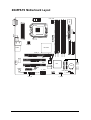
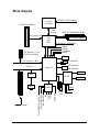
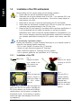
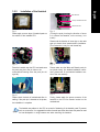
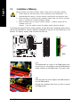
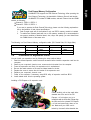
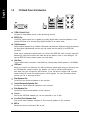
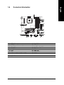
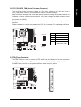
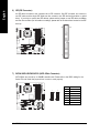
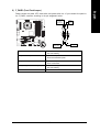
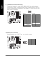
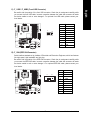
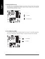
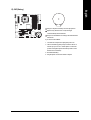
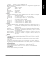
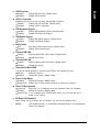
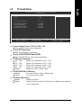
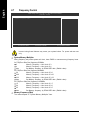
8I945PE-FS Intel® Pentium® 4 LGA775 Processor Motherboard User's Manual Rev. 1001 8I945PE-FS Motherboard Layout LGA775 ATX LAN USB 1394 USB 8I945PE SPDIF BIOS_RE COMA IT8712 CPU_FAN ATX_12V DDRII4 DDRII3 DDRII1 PCIE_16 DDRII2 Intel 945P AUDIO IDE FDD PCI1 82562 PCIE_1 F-AUDIO SATA3 SATA2 BAT TSB43AB23 BZ CODEC ICH7 F_1394 SYS_FAN F_USB1 SATA1 SATA0 FS BIOS PCI2 CLR_CMOS F_PANEL F_USB2 AUX_IN - 2 - Block Diagram CPUCLK+/-(200/133MHz) LGA775 Processor PCI-ECLK(100MHz) Host Interface PCI Express x16 Intel 945P MCH DDRII 667/533/400MHz DIMM Dual Channel Memory MCHCLK (133/200MHz) 66MHz 33MHz 14.318MHz 48MHz 1 PCI Express x 1 Port PCI-ECLK(100MHz) BIOS PCI Express x1 Bus PCI Bus 4 Serial ATA ATA33/66/100 IDE Channels Intel ICH7 Floppy 82562 IT8712 PCICLK(33MHz) - 3 - 24MHz SPDIF Out 2 PCI CODEC Center/Subwoofer Speaker Out Surround Speaker Out Side Speaker Out MIC Line-Out Line-In RJ45 8 USB Ports 33MHz COM Port English Chapter 1 Hardware Installation 1-1 Feature Summary CPU Chipset Memory Slots IDE Connections FDD Connections Onboard SATA 3Gb/s Peripherals Onboard LAN Onboard Audio Supports Intel® Pentium® D / Pentium® 4 LGA775 CPU Supports 1066/800/533MHz FSB L2 cache varies with CPU Northbridge: Intel® 945P Express chipset Southbridge: Intel® ICH7 Supported on the Win 2000/XP/MCE operating systems 4 DDRII DIMM memory slots (supports up to 4GB memory) (Note 1) Supports dual channel DDR II 667(Note 2)/533/400 DIMM Supports 1.8V DDR II DIMM 1 PCI Express x 16 slot 1 PCI Express x 1 slot 2 PCI slots 1 IDE connection (UDMA 33/ATA 66/ATA 100), allows connection of 2 IDE devices 1 FDD connection, allows connection of 2 FDD devices 4 SATA 3Gb/s connections Supported on the Win 2000/XP/MCE operating systems 1 parallel port supporting Normal/EPP/ECP mode 1 COMA port 8 USB 2.0/1.1 ports 1 front audio connector Onboard 82562 chip (10/100 Mbit) 1 RJ 45 port ALC880 CODEC Supports Jack Sensing function Supports 2 / 4 / 6 / 8 channel audio Supports Line In ; Line Out (Front Speaker Out) ; MIC ; Surround Speaker Out (Rear Speaker Out) ; Center/Subwoofer Speaker Out ; Side Speaker Out connection Supports SPDIF Out connection AUX_In (Note 1) Due to standard PC architecture, a certain amount of memory is reserved for system usage and therefore the actual memory size is less than the stated amount. For example, 4 GB of memory size will instead be shown as 3.xxGB memory during system startup. (Note 2) To use a DDRII 667 memory module on the motherboard, you must install an 800/1066MHz FSB processor . 8I945PE-FS Motherboard - 4 - BIOS Form Factor IT8712 System voltage detection CPU temperature detection CPU / System fan speed detection CPU warning temperature CPU / System fan failure warning CPU smart fan control Use of licensed AWARD BIOS Micro ATX form factor; 24.4 cm x 24.4cm - 5 - English I/O Control Hardware Monitor Hardware Installation English 1-2 Installation of the CPU and Heatsink Before installing the CPU, please comply with the following conditions: 1. Please make sure that the motherboard supports the CPU. 2. Please take note of the one indented corner of the CPU. If you install the CPU in the wrong direction, the CPU will not insert properly. If this occurs, please change the insert direction of the CPU. 3. Please add an even layer of heat sink paste between the CPU and heatsink. 4. Please make sure the heatsink is installed on the CPU prior to system use, otherwise overheating and permanent damage of the CPU may occur. 5. Please set the CPU host frequency in accordance with the processor specifications. It is not recommended that the system bus frequency be set beyond hardware specifications since it does not meet the required standards for the peripherals. If you wish to set the frequency beyond the proper specifications, please do so according to your hardware specifications including the CPU, graphics card, memory, hard drive, etc. HT functionality requirement content : Enabling the functionality of Hyper-Threading Technology for your computer system requires all of the following platform components: - CPU: An Intel® Pentium 4 Processor with HT Technology - Chipset: An Intel® Chipset that supports HT Technology - BIOS: A BIOS that supports HT Technology and has it enabled - OS: An operation system that has optimizations for HT Technology 1-2-1 Installation of the CPU Metal Lever Fig. 1 Gently lift the metal lever located on the CPU socket to the upright position. Fig. 2 Remove the plastic covering on the CPU socket. Fig. 3 Notice the small gold colored triangle located on the edge of the CPU socket. Align the Fig. 4 Once the CPU is properly inserted, please replace the load plate and push the metal lever back into its original position. indented corner of the CPU with the triangle and gently insert the CPU into position. (Grasping the CPU firmly between your thumb and forefinger, carefully place it into the socket in a straight and downwards motion. Avoid twisting or bending motions that might cause damage to the CPU during installation.) 8I945PE-FS Motherboard - 6 - Installation of the Heatsink Male Push Pin The top of Female Push Pin Female Push Pin Fig.1 Please apply an even layer of heatsink paste on the surface of the installed CPU. Fig. 2 (Turning the push pin along the direction of arrow is to remove the heatsink, on the contrary, is to install.) Please note the direction of arrow sign on the male push pin doesn't face inwards before installation. (This instruction is only for Intel boxed fan) Fig. 3 Place the heatsink atop the CPU and make sure the push pins aim to the pin hole on the motherboard.Pressing down the push pins diagonally. Fig. 4 Please make sure the Male and Female push pin are joined closely. (for detailed installation instructions, please refer to the heatsink installation section of the user manual) Fig. 5 Please check the back of motherboard after installing. If the push pin is inserted as the picture, the installation is complete. Fig. 6 Finally, please attach the power connector of the heatsink to the CPU fan header located on the motherboard. The heatsink may adhere to the CPU as a result of hardening of the heatsink paste.To prevent such an occurrence, it is suggested that either thermal tape rather than heat sink paste be used for heat dissipation or using extreme care when removing the heatsink. - 7 - Hardware Installation English 1-2-2 Installation of Memory Before installing the memory modules, please comply with the following conditions: 1 . Please make sure that the memory used is supported by the motherboard. It is recommended that memory of similar capacity, specifications and brand be used. 2 . Before installing or removing memory modules, please make sure that the computer power is switched off to prevent hardware damage. 3 . Memory modules have a foolproof insertion design. A memory module can be installed in only one direction. If you are unable to insert the module, please switch the direction. The motherboard supports DDR II memory modules, whereby BIOS will automatically detect memory capacity and specifications. Memory modules are designed so that they can be inserted only in one direction. The memory capacity used can differ with each slot. Notch FS English 1-3 DDR II Fig.1 The DIMM socket has a notch, so the DIMM memory module can only fit in one direction. Insert the DIMM memory module vertically into the DIMM socket. Then push it down. Fig.2 Close the plastic clip at both edges of the DIMM sockets to lock the DIMM module. Reverse the installation steps when you wish to remove the DIMM module. 8I945PE-FS Motherboard - 8 - GA-8I945PE-FS supports the Dual Channel Technology. After operating the Dual Channel Technology, the bandwidth of Memory Bus will add double. GA-8I945PE-FS includes 4 DIMM sockets, and each Channel has two DIMM sockets as following: Channel A : DDR II 1, DDR II 2 Channel B : DDR II 3, DDR II 4 If you want to operate the Dual Channel Technology, please note the following explanations due to the limitation of Intel chipset specifications. 1. Dual Channel mode will not be enabled if only one DDR II memory module is installed. 2. To enable Dual Channel mode with two or four memory modules (it is recommended to use memory modules of identical brand, size, chips, and speed), you must install them into DIMM sockets of the same color. The following is a Dual Channel Memory configuration table: (DS: Double Side, SS: Single Side) 2 memory modules DDR II 1 DS/SS DDR II 2 X DDR II 3 DS/SS DDR II 4 X 4 memory modules X DS/SS DS/SS DS/SS X DS/SS DS/SS DS/SS 1-4 Installation of Expansion Cards You can install your expansion card by following the steps outlined below: 1. Read the related expansion card's instruction document before install the expansion card into the computer. 2. Remove your computer's chassis cover, screws and slot bracket from the computer. 3. Press the expansion card firmly into expansion slot in motherboard. 4. Be sure the metal contacts on the card are indeed seated in the slot. 5. Replace the screw to secure the slot bracket of the expansion card. 6. Replace your computer's chassis cover. 7. Power on the computer, if necessary, setup BIOS utility of expansion card from BIOS. 8. Install related driver from the operating system. Installing a PCI Express x 16 expansion card: Please carefully pull out the small whitedrawable bar at the end of the PCI Express x 16 slot when you try to install/Uninstall the VGA card. Please align the VGA card to the onboard PCI Express x 16 slot and press firmly down on the slot .Make sure your VGA card is locked by the small white-drawable bar. - 9 - Hardware Installation English Dual Channel Memory Configuration English 1-5 I/O Back Panel Introduction COM A (Serial Port) Connects to serial-based mouse or data processing devices. SPDIF Out The SPDIF optical output port is capable of providing digital audio to external speakers or com pressed AC3 data to an external Dolby Digital Decoder via an optical cable. 1394 Connector Serial interface standard set by Institute of Electrical and Electronics Engineers, which has features like high speed, highbandwidth and hot plug. Be careful with the polarity of the IEEE1394 connector. Check the pin assignment carefully while you connect the IEEE1394 cable, incorrect connection between the cable and connector will make the device unable to work or even damage it. For optional IEEE1394 cable, please contact your local dealer. LAN Port The provided Internet connection is fast Ethernet, providing data transfer speeds of 10/100Mbps. USB port Before you connect your device(s) into USB connector(s), please make sure your device(s) such as USB keyboard, mouse, scanner, zip, speaker...etc. have a standard USB interface. Also make sure your OS supports USB controller. If your OS does not support USB controller, please contact OS vendor for possible patch or driver upgrade. For more information please contact your OS or device(s) vendors. Rear Speaker Out Connect the rear surround speakers to this connector. Center/Subwoofer Speaker Out Connect the Center/Subwoofer speakers to this connector. Side Speaker Out Connect the side surround speakers to this connector. Line In Devices like CD-ROM, walkman etc. can be connected to Line In jack. Line Out (Front Speaker Out) Connect the stereo speakers, earphone or front surround speakers to this connector. MIC In Microphone can be connected to MIC In jack. 8I945PE-FS Motherboard - 10 - Connectors Introduction English 1-6 3 2 13 6 1 5 FS 7 15 14 9 10 4 1) 2) 3) 4) 5) 6) ATX_12V ATX (Power Connector) CPU_FAN SYS_FAN FDD IDE 7) SATA0 / SATA1 / SATA2 / SATA3 8) F_PANEL 11 12 9) 10) 11) 12) 13) 14) 8 F_AUDIO AUX_IN F_USB1 / F_USB2 F_1394 BIOS_RE CLR_CMOS 15) BAT - 11 - Hardware Installation With the use of the power connector, the power supply can supply enough stable power to all the components on the motherboard. Before connecting the power connector, please make sure that all components and devices are properly installed. Align the power connector with its proper location on the motherboard and connect tightly. The ATX_12V power connector mainly supplies power to the CPU. If the ATX_12V power connector is not connected, the system will not start. Caution! Please use a power supply that is able to handle the system voltage requirements. It is recommended that a power supply that can withstand high power consumption be used (300W or greater). If a power supply is used that does not provide the required power, the result can lead to an unstable system or a system that is unable to start. 2 1 4 3 13 Pin No. 1 FS English 1/2) ATX_12V/ATX (Power Connector) 24 8I945PE-FS Motherboard - 12 - 12 Definition 1 2 GND GND 3 4 +12V +12V Pin No. 1 2 Definition 3.3V 3.3V 3 4 GND +5V 5 6 GND +5V 7 8 GND Power Good 9 10 5V SB(stand by +5V) +12V 11 12 +12V(Only for 24pins ATX) 3.3V(Only for 24pins ATX) 13 14 3.3V -12V 15 16 GND PS_ON(soft On/Off) 17 18 GND GND 19 20 GND -5V 21 22 +5V +5V 23 24 +5V(Only for 24pins ATX) GND(Only for 24pins ATX) The cooler fan power connector supplies a +12V power voltage via a 3-pin/4-pin (only for CPU_FAN) power connector and possesses a foolproof connection design. Most coolers are designed with color-coded power connector wires. A red power connector wire indicates a positive connection and requires a +12V power voltage. The black connector wire is the ground wire (GND). Please remember to connect the power to the cooler to prevent system overheating and failure. Caution! Please remember to connect the power to the CPU fan to prevent CPU overheating and failure. Pin No. CPU_FAN FS 1 Definition 1 2 GND +12V 3 4 Sense Speed Control (Only for CPU_FAN) 1 SYS_FAN 5) FDD (Floppy Connector) The FDD connector is used to connect the FDD cable while the other end of the cable connects to the FDD drive. The types of FDD drives supported are: 360KB, 720KB, 1.2MB, 1.44MB and 2.88MB. Please connect the red power connector wire to the pin1 position. 33 2 1 FS 34 - 13 - Hardware Installation English 3/4) CPU_FAN / SYS_FAN (Cooler Fan Power Connector) An IDE device connects to the computer via an IDE connector. One IDE connector can connect to one IDE cable, and the single IDE cable can then connect to two IDE devices (hard drive or optical drive). If you wish to connect two IDE devices, please set the jumper on one IDE device as Master and the other as Slave (for information on settings, please refer to the instructions located on the IDE device). 39 FS 40 2 1 7) SATA0/SATA1/SATA2/SATA3 (SATA 3Gb/s Connector) SATA 3Gb/s can provide up to 300MB/s transfer rate. Please refer to the BIOS setting for the Serial ATA and install the proper driver in order to work properly. Pin No. 1 7 FS English 6) IDE (IDE Connector) 8I945PE-FS Motherboard - 14 - 7 1 Definition 1 2 GND TXP 3 4 TXN GND 5 6 RXN RXP 7 GND Please connect the power LED, reset switch and power switch etc. of your chassis front panel to the F_PANEL connector according to the pin assignment below. Message LED/ Power/ Sleep LED Power Switch PWPW+ MSGMSG+ 2 1 10 9 FS NC RES+ RESHDHD+ IDE Hard Disk Active LED HD (IDE Hard Disk Active LED) Pin 1: LED anode(+) Pin 2: LED cathode(-) RES (Reset Switch) Open: Normal Operation Close: Reset Hardware System PW (Power Switch) Open: Normal Operation Close: Power On/Off MSG (Message LED/Power/Sleep LED) Pin 1: LED anode(+) Pin 2: LED cathode(-) NC NC - 15 - Reset Switch Hardware Installation English 8) F_PANEL (Front Panel Jumper) This connector is supported to connect HD(High Definition) Audio. Check the pin assignment carefully while you connect the audio panel cable, incorrect connection between the cable and connector will make the device unable to work or even damage it. For optional audio panel cable, please contact your local dealer. 2 10 1 9 HD Audio: FS Pin No. AC'97 Audio: Definition Pin No. MIC2_L GND 1 2 MIC GND 3 4 MIC2_R -ACZ_DET 3 4 MIC Power N/A 5 6 Line2_R FSENSE1 5 6 Line Out (R) N/A 7 8 FAUOIO_JD No Pin 7 8 N/A No Pin 9 10 LINE2_L FSENSE2 9 10 N/A Line Out (L) Connect other device (such as PCI TV Tuner audio out) to the connector. Pin No. 1 8I945PE-FS Motherboard - 16 - Definition 1 2 10) AUX_IN (AUX In Connector) FS English 9) F_AUDIO (Front Audio Panel Connector) Definition 1 2 AUX-L GND 3 4 GND AUX -R Be careful with the polarity of the front USB connector. Check the pin assignment carefully while you connect the front USB cable, incorrect connection between the cable and connector will make the device unable to work or even damage it. For optional front USB cable, please contact your local dealer. Pin No. Definition 1 2 Power Power 10 3 4 USB DXUSB Dy- 1 9 5 6 USB DX+ USB Dy+ 7 8 GND GND 9 10 No Pin NC FS 2 12) F_1394 (IEEE 1394 Connector) Serial interface standard set by Institute of Electrical and Electronics Engineers, which has features like high speed, high bandwidth and hot plug. Be careful with the polarity of the IEEE1394 connector. Check the pin assignment carefully while you connect the IEEE1394 cable, incorrect connection between the cable and connector will make the device unable to work or even damage it. For optional IEEE1394 cable, please contact your local dealer. Pin No. 1 2 FS 1 - 17 - 10 9 Definition TPA2+ 2 3 TPA2GND 4 5 GND TPB2+ 6 7 TPB2Power 8 9 Power No Pin 10 GND Hardware Installation English 11) F_ USB1 / F_USB2 (Front USB Connector) If the BIOS file on the motherboard is damaged, set this jumper to Recovery mode. Insert the floppy disk containing the complete BIOS file and then restart the system. System will write the BIOS file to the BIOS ROM automatically at startup. 1-2: N ormal 1 2-3: BIOS Recovery FS 1 14) CLR_CMOS (Clear CMOS) You may clear the CMOS data to its default values by this jumper. To clear CMOS, temporarily short 1-2 pin. Default doesn't include the "Shunter" to prevent from improper use this jumper. FS English 13) BIOS_RE (BIOS Recovery) 8I945PE-FS Motherboard - 18 - 1 1-2: Clear CMOS 1 2-3 : Normal English 15) BAT(Battery) Danger of explosion if battery is incorrectly replaced. FS Replace only with the same or equivalent type recommended by the manufacturer. Dispose of used batteries according to the manufacturer's instructions. If you want to erase CMOS... 1. Turn OFF the computer and unplug the power cord. 2. Take out the battery gently and put it aside for about 10 minutes (Or you can use a metal object to connect the positive and negative pins in the battery holder to make them short for one minute). 3. Re-install the battery. 4. Plug the power cord and turn ON the computer. - 19 - Hardware Installation English 8I945PE-FS Motherboard - 20 - BIOS Setup BIOS (Basic Input and Output System) includes a CMOS SETUP utility which allows user to configure required settings or to activate certain system features. The CMOS SETUP saves the configuration in the CMOS SRAM of the motherboard. When the power is turned off, the battery on the motherboard supplies the necessary power to the CMOS SRAM. CONTROL KEYS < >< >< <Enter> <Esc> >< <Page Up> <Page Down> <F1> <F2> <F5> <F7> <F9> <F10> > Move to select item Select Item Main Menu - Quit and not save changes into CMOS Status Page Setup Menu and Option Page Setup Menu - Exit current page and return to Main Menu Increase the numeric value or make changes Decrease the numeric value or make changes General help, only for Status Page Setup Menu and Option Page Setup Menu Item Help Restore the previous CMOS value from CMOS, only for Option Page Setup Menu Default Setting System Information Save all the CMOS changes, only for Main Menu Main Menu The on-line description of the highlighted setup function is displayed at the bottom of the screen. Status Page Setup Menu / Option Page Setup Menu Press F1 to pop up a small help window that describes the appropriate keys to use and the possible selections for the highlighted item. To exit the Help Window press <Esc>. - 21 - BIOS Setup English Chapter 2 English The Main Menu (BIOS Ver. 10d) Once you enter Award BIOS CMOS Setup Utility, the Main Menu (as figure below) will appear on the screen. Use arrow keys to select among the items and press <Enter> to accept or enter the sub-menu. CMOS Setup Utility-Copyright (C) 1984-2005 Award Software ` Standard CMOS Features Load Fail-Safe Defaults ` ` Advanced BIOS Features Integrated Peripherals Load Optimized Defaults Set Supervisor Password ` ` Power Management Setup PnP/PCI Configurations Set User Password Save & Exit Setup ` ` PC Health Status Frequency/Voltage Control Exit Without Saving KLJI: Select Item ESC: Quit F10: Save & Exit Setup Time, Date, Hard Disk Type... Standard CMOS Features This setup page includes all the items in standard compatible BIOS. Advanced BIOS Features This setup page includes all the items of Award special enhanced features. Integrated Peripherals This setup page includes all onboard peripherals. Power Management Setup This setup page includes all the items of Green function features. PnP/PCI Configuration This setup page includes all the configurations of PCI & PnP ISA resources. PC Health Status This setup page is the System auto detect Temperature, voltage, fan, speed. Frequency / Voltage Control This setup page is control CPU clock and frequency ratio. Load Fail-Safe Defaults Fail-Safe Defaults indicates the value of the system parameters which the system would be in safe configuration. Load Optimized Defaults Optimized Defaults indicates the value of the system parameters which the system would be in best performance configuration. GA-8I945PE-FS Motherboard - 22 - Change, set, or disable password. It allows you to limit access to the system and Setup, or just to Setup. Set User Password Change, set, or disable password. It allows you to limit access to the system. Save & Exit Setup Save CMOS value settings to CMOS and exit setup. Exit Without Saving Abandon all CMOS value changes and exit setup. - 23 - BIOS Setup English Set Supervisor Password English 2-1 Standard CMOS Features CMOS Setup Utility-Copyright (C) 1984-2005 Award Software Standard CMOS Features ` ` ` ` ` ` Date (mm:dd:yy) Time (hh:mm:ss) Fri, Sep 2 2005 20:1:24 Item Help Menu Level` IDE Channel 0 Master IDE Channel 0 Slave IDE Channel 2 Master IDE Channel 2 Slave IDE Channel 3 Master IDE Channel 3 Slave [None] [None] [None] [None] [None] [None] Change the day, month, year Drive A [None] Halt On [All, But Keyboard] Base Memory Extended Memory Total Memory 640K 511M 512M KLJI: Move Enter: Select F5: Previous Values +/-/PU/PD: Value F6: Fail-Safe Defaults <Week> Sun. to Sat. <Month> Jan. to Dec. <Day> 1 to 31 (or maximum allowed in the month) <Year> 1999 to 2098 F10: Save ESC: Exit F1: General Help F7: Optimized Defaults Date The date format is <week>, <month>, <day>, <year>. Week The week, from Sun to Sat, determined by the BIOS and is display only Month The month, Jan. Through Dec. Day The day, from 1 to 31 (or the maximum allowed in the month) Year The year, from 1999 through 2098 Time The times format in <hour> <minute> <second>. The time is calculated base on the 24-hour military-time clock. For example, 1 p.m. is 13:00:00. IDE Channel 0 Master, Slave IDE HDD Auto-Detection Press "Enter" to select this option for automatic device detection. IDE Device Setup. You can use one of three methods: Auto Allows BIOS to automatically detect IDE devices during POST(default) None Select this if no IDE devices are used and the system will skip the automatic detection step and allow for faster system start up. Manual User can manually input the correct settings Access Mode Use this to set the access mode for the hard drive. The four options are: CHS/LBA/Large/Auto(default:Auto) IDE Channel 2/3 Master, Slave IDE HDD Auto-Detection Press "Enter" to select this option for automatic device detection. Extended IDE Drive SATA devices setup. You can use one of two methods: Auto Allows BIOS to automatically detect SATA IDE devices during POST. (Default value) None Select this if no SATA IDE devices are used and the system will skip the automatic detection step and allow for faster system start up. Access Mode Use this to set the access mode for the hard drive. The two options are: Large/Auto(default:Auto) GA-8I945PE-FS Motherboard - 24 - Drive A The category identifies the types of floppy disk drive A that has been installed in the computer. None No floppy drive installed 360K, 5.25" 5.25 inch PC-type standard drive; 360K byte capacity. 1.2M, 5.25" 5.25 inch AT-type high-density drive; 1.2M byte capacity (3.5 inch when 3 Mode is Enabled). 720K, 3.5" 3.5 inch double-sided drive; 720K byte capacity 1.44M, 3.5" 3.5 inch double-sided drive; 1.44M byte capacity. 2.88M, 3.5" 3.5 inch double-sided drive; 2.88M byte capacity. Halt on The category determines whether the computer will stop if an error is detected during power up. No Errors The system boot will not stop for any error that may be detected and you will be prompted. All Errors Whenever the BIOS detects a non-fatal error the system will be stopped. All, But Keyboard The system boot will not stop for a keyboard error; it will stop for all other errors. (Default value) All, But Diskette The system boot will not stop for a disk error; it will stop for all other errors. All, But Disk/Key The system boot will not stop for a keyboard or disk error; it will stop for all other errors. Memory The category is display-only which is determined by POST (Power On Self Test) of the BIOS. Base Memory The POST of the BIOS will determine the amount of base (or conventional) memory installed in the system. The value of the base memory is typically 512K for systems with 512K memory installed on the motherboard, or 640K for systems with 640K or more memory installed on the motherboard. Extended Memory The BIOS determines how much extended memory is present during the POST. This is the amount of memory located above 1 MB in the CPU's memory address map. Total Memory This item displays the memory size that used. - 25 - BIOS Setup English Capacity Capacity of currently installed hard disk. Hard drive information should be labeled on the outside drive casing. Enter the appropriate option based on this information. Cylinder Number of cylinders Head Number of heads Precomp Write precomp Landing Zone Landing zone Sector Number of sectors English 2-2 Advanced BIOS Features CMOS Setup Utility-Copyright (C) 1984-2005 Award Software Advanced BIOS Features ` Hard Disk Boot Priority BIOS Flash Protection First Boot Device Second Boot Device Third Boot Device Boot Up Floppy Seek Boot Up NumLock Password Check # CPU Hyper-Threading Limit CPUID Max. to 3 No-Execute Memory Protect (Note) CPU Enhanced Halt (C1E) (Note) CPU EIST Function (Note) Full Screen LOGO Show Intel OnScreen Branding KLJI: Move Enter: Select F5: Previous Values [Press Enter] [Auto] [CDROM] [Floppy] [Hard Disk] [Disabled] [On] [Setup] [Enabled] [Disabled] [Enabled] [Enabled] [Enabled] [Enabled] [Enabled] +/-/PU/PD: Value F6: Fail-Safe Defaults F10: Save Item Help Menu Level` ESC: Exit F1: General Help F7: Optimized Defaults " # " System will detect automatically and show up when you install the Intel® Pentium® 4 processor with HT Technology. Hard Disk Boot Priority Select boot sequence for onboard(or add-on cards) SCSI, RAID, etc. Use < > or < > to select a device, then press<+> to move it up, or <-> to move it down the list. Press <ESC> to exit this menu. BIOS Flash Protection This field lets you determine the states that flash BIOS Auto BIOS enables flash write access automatically when updating BIOS data/ DMI/ESCD. (Default Value) Enabled During POST, DMI/ESCD would not be updated. But flash tools can update BIOS always. First / Second / Third Boot Device Floppy LS120 Hard Disk CDROM ZIP USB-FDD USB-ZIP USB-CDROM USB-HDD LAN Disabled (Note) Select your Select your Select your Select your Select your Select your Select your Select your Select your Select your Disable this boot device priority by Floppy. boot device priority by LS120. boot device priority by Hard Disk. boot device priority by CDROM. boot device priority by ZIP. boot device priority by USB-FDD. boot device priority by USB-ZIP. boot device priority by USB-CDROM. boot device priority by USB-HDD. boot device priority by LAN. function. This item will show up when you install a processor which supports this function. GA-8I945PE-FS Motherboard - 26 - During POST, BIOS will determine if the installed floppy disk drive is 40 or 80 tracks. 360K type is 40 tracks 720K, 1.2M and 1.44M are all 80 tracks. Disabled BIOS will not search for the type of floppy disk drive by track number. Note that there will not be any warning message if the drive installed is 360K. (Default value) Enabled BIOS searches for floppy disk drive to determine if it is 40 or 80 tracks. Note that BIOS can not tell from 720K, 1.2M or 1.44M drive type as they are all 80 tracks. Boot Up Num-Lock On Off Keypad is number keys. (Default value) Keypad is arrow keys. Password Check Setup The system will boot but will not access to Setup page if the correct password is not entered at the prompt. (Default value) System The system will not boot and will not access to Setup page if the correct password is not entered at the prompt. If you want to cancel the setting of password, please just press ENTER to make [SETUP] empty. CPU Hyper-Threading This option appears only when the processor you install supports Intel® Hyper-Threading Technology. Enabled Enable CPU Hyper-Threading feature. Please note that this feature only works for operating system with multiprocessors mode supported. (Default value) Disabled Disable CPU Hyper-Threading. Limit CPUID Max. to 3 Enabled Disabled Limit CPUID Maximum value to 3 when use older OS like NT4. Disables CPUID Limit for windows XP. (Default value) No-Execute Memory Protect (Note) Enabled Disabled Enables No-Execute Memory Protect function. (Default value) Disables No-Execute Memory Protect function. CPU Enhanced Halt (C1E) (Note) Enabled Disabled Enables CPU Enhanced Halt (C1E) function. (Default value) Disables CPU Enhanced Halt (C1E) function. CPU EIST Function (Note) Enabled Disabled Enable CPU EIST function. (Default value) Disable CPU EIST function. Full Screen LOGO Show Enabled Disabled Display Full Screen LOGO during POST. (Default value) Don't dispaly Full Screen LOGO during POST. Intel OnScreen Branding Enabled Enable this function. (Default value) Disabled Disable this function. (Note) This item will show up when you install a processor which supports this function. - 27 - BIOS Setup English Boot Up Floppy Seek English 2-3 Integrated Peripherals CMOS Setup Utility-Copyright (C) 1984-2005 Award Software Integrated Peripherals On-Chip Primary PCI IDE On-Chip SATA Mode x PATA IDE Set to SATA Port 0/2 Set to SATA Port 1/3 Set to USB Controller USB 2.0 Controller USB Keyboard Support USB Mouse Support Azalia Codec Onboard H/W 1394 Onboard H/W LAN Onboard LAN Boot ROM Power On By Mouse Power On By Keyboard x KB Power ON Password Onboard FDC Controller Onboard Serial Port 1 AC Back Function [Enabled] [Auto] Ch.0 Master/Slave Ch.2 Master/Slave Ch.3 Master/Slave [Enabled] [Enabled] [Enabled] [Enabled] [Auto] [Enabled] [Enabled] [Disabled] [Disabled] [Disabled] Enter [Enabled] [3F8/IRQ4] [Memory] KLJI: Move Enter: Select F5: Previous Values +/-/PU/PD: Value F6: Fail-Save Default F10: Save Item Help Menu Level` ESC: Exit F1: General Help F7: Optimized Defaults On-Chip Primary PCI IDE Enabled Disabled Enable onboard 1st channel IDE port. (Default value) Disable onboard 1st channel IDE port. On-Chip SATA Mode Disabled Auto Combined Enhanced Non-Combined Disable this function. BIOS will auto detect. (Default value) Set On-Chip SATA mode to Combined, you can use up to 4 HDDs on the motherboard; 2 for SATA and the other for PATA. Set On-Chip SATA mode to Enhanced, the motherboard allows up to 6 HDDs to use; 4 SATA HDDs plus PATA HDDs. Set On-Chip SATA mode to Non-Combined, SATA will be simulated to PATA mode. Support a maximum of 4 SATA devices. PATA devices will be ignored. PATA IDE Set to Ch.1 Master/Slave Ch.0 Master/Slave Set PATA IDE to Ch. 1 Master/Slave. Set PATA IDE to Ch. 0 Master/Slave. (Default value) SATA Port 0/2 Set to This value will auto make by the setting "On-Chip SATA Mode" and "PATA IDE Set to". If PATA IDE were set to Ch. 1 Master/Slave, this function will auto set to Ch. 0 Master/Slave. SATA Port 1/3 Set to This value will auto make by the setting "On-Chip SATA Mode" and "PATA IDE Set to". If PATA IDE were set to Ch. 0 Master/Slave, this function will auto set to Ch. 1 Master/Slave. GA-8I945PE-FS Motherboard - 28 - Enabled Disabled English USB Controller Enable USB Controller. (Default value) Disable USB Controller. USB 2.0 Controller Disable this function if you are not using onboard USB 2.0 feature. Enabled Enable USB 2.0 Controller. (Default value) Disabled Disable USB 2.0 Controller. USB Keyboard Support Enabled Disabled Enable USB Keyboard Support. (Default value) Disable USB Keyboard Support. USB Mouse Support Enabled Disabled Enable USB Mouse Support. (Default value) Disable USB Mouse Support. Azalia Codec Auto Disabled Auto detect Azalia audio function. (Default value) Disable Azalia audio function. Onboard H/W 1394 Enabled Disabled Enable onboard IEEE 1394 function. (Default value) Disable this function. Onboard H/W LAN Enabled Disabled Enable Onboard H/W LAN function. (Default value) Disable this function. Onboard LAN Boot ROM This function decide whether to invoke the boot ROM of the onboard LAN chip. Enabled Enable this function. Disabled Disable this function. (Default value) Power On By Mouse Disabled Double Click Disable this function. (Default value) Double click on PS/2 mouse left button to power on the system. Power On By Keyboard Password Enter from 1 to 5 characters to set the Keyboard Power On Password. Disabled Disable this function. (Default value) Keyboard 98 If your keyboard have "POWER Key" button, you can press the key to power on the system. KB Power ON Password When "Power On by Keyboard" set at Password, you can set the password here. Enter Input password (from 1 to 5 characters) and press Enter to set the Keyboard Power On password. - 29 - BIOS Setup English Onboard FDC Controller Enabled Disabled Enable onboard FDC controller. (Default value) Disable onboard FDC controller. Onboard Serial Port 1 3F8/IRQ4 2F8/IRQ3 3E8/IRQ4 2E8/IRQ3 Disabled Enable onboard Serial port 1 and Enable onboard Serial port 1 and Enable onboard Serial port 1 and Enable onboard Serial port 1 and Disable onboard Serial port 1. address address address address is is is is 3F8/IRQ4. (Default value) 2F8. 3E8. 2E8. AC Back Function Soft-Off Full-On Memory When AC-power back to the system, the system will be in "Off" state. When AC-power back to the system, the system always in "On" state. When AC-power back to the system, the system will return to the Last state before AC-power off. (Default value) GA-8I945PE-FS Motherboard - 30 - Power Management Setup English 2-4 CMOS Setup Utility-Copyright (C) 1984-2005 Award Software Power Management Setup ACPI Suspend Type USB Device Wake-Up From S3 Soft-Off by PWR-BTTN PME Event Wake Up Power On by Ring Resume by Alarm x Date (of Month) Alarm x Time (hh:mm:ss) Alarm KLJI: Move Enter: Select F5: Previous Values [S3(STR)] [Enabled] [Instant-Off] [Enabled] [Enabled] [Disabled] 0 0:0:0 +/-/PU/PD: Value F6: Fail-Safe Default Item Help Menu Level` F10: Save ESC: Exit F7: Optimized Defaults F1: General Help ACPI Suspend Type S1(POS) S3(STR) Set ACPI suspend type to S1/POS(Power On Suspend). Set ACPI suspend type to S3/STR(Suspend To RAM). (Default value) USB Device Wake-Up From S3 Disabled Enabled Disable USB Device Wake-Up from S3. Enable USB Device Wake-Up from S3. (Default value) Soft-off by PWR-BTTN Instant-off Press power button then Power off instantly. (Default value) Delay 4 Sec. Press power button 4 sec. to Power off. Enter suspend if button is pressed less than 4 sec. PME Event Wake Up Disabled Enabled Disable this function. Enable PME Event Wake up. (Default value) Power On by Ring Disabled Enabled Disable Power on by Ring function. Enable Power on by Ring function. (Default value) Resume by Alarm You can set "Resume by Alarm" item to enabled and key in Data/time to power on system. Disabled Disable this function. (Default value) Enabled Enable alarm function to POWER ON system. If Resume by alarm is Enabled. Date (of Month) Alarm : 0~31 Time (hh: mm: ss) Alarm : (0~23) : (0~59) : (0~59) - 31 - BIOS Setup English 2-5 PnP/PCI Configurations CMOS Setup Utility-Copyright (C) 1984-2005 Award Software PnP/PCI Configurations Resources Controlled By x IRQ Resources [Auto] Press Enter KLJI: Move Enter: Select F5: Previous Values +/-/PU/PD: Value F6: Fail-Save Default F10: Save Item Help Menu Level` ESC: Exit F1: General Help F7: Optimized Defaults Resources Controlled By Manual Auto User can set the PnP resource (I/O Address, IRQ & DMA channels) used by legacy ISA DEVICE. BIOS automatically use these PnP rescuers. (Default value) IRQ assigned ( 3,4,5,7,9,10,11,12,14,15 ) PCI Device Reserved This IRQ assigns for PCI device. (Default value) Reserved this IRQ for other device. GA-8I945PE-FS Motherboard - 32 - PC Health Status CMOS Setup Utility-Copyright (C) 1984-2005 Award Software PC Health Status Vcore VCC18 +3.3V +12V Current CPU Temperature Current CPU FAN Speed Current SYSTEM FAN Speed CPU Warning Temperature CPU FAN Fail Warning SYSTEM FAN Fail Warning CPU Smart FAN Control KLJI: Move Enter: Select F5: Previous Values 1.312V 1.792V 3.232V 11.287V 49oC 3515 RPM 0 RPM [Disabled] [Disabled] [Disabled] [Enabled] +/-/PU/PD: Value F6: Fail-Save Default Item Help Menu Level` F10: Save ESC: Exit F1: General Help F7: Optimized Defaults Current Voltage(V) Vcore / VCC18 / +3.3V / +12V Detect system's voltage status automatically. Current CPU Temperature Detect CPU temperature automatically. Current CPU/SYSTEM FAN Speed (RPM) Detect CPU/SYSTEM Fan speed status automatically. CPU Warning Temperature 60oC / 140oF 70oC / 158oF 80oC / 176oF 90oC / 194oF Disabled Monitor Monitor Monitor Monitor Disable CPU temperature at 60oC / 140oF. CPU temperature at 70oC / 158oF. CPU temperature at 80oC / 176oF. CPU temperature at 90oC / 194oF. this function. (Default value) CPU/SYSTEM FAN Fail Warning Disabled Enabled Fan warning function disable. (Default value) Fan warning function enable. CPU Smart FAN Control Disabled Enabled Disable this function. When this function is enabled, CPU fan will run at different speed depending on CPU temperature. - 33 - BIOS Setup English 2-6 English 2-7 Frequency Control CMOS Setup Utility-Copyright (C) 1984-2005 Award Software Frequency Control System Memory Multiplier Memory Frequency (Mhz) KLJI: Move Enter: Select F5: Previous Values [Auto] 533 +/-/PU/PD: Value F6: Fail-Save Default Item Help Menu Level` F10: Save ESC: Exit F1: General Help F7: Optimized Defaults Incorrect using these features may cause your system broken. For power end-user use only. System Memory Multiplier Wrong frequency may make system can't boot, clear CMOS to for FSB(Front Side Bus) frequency=533MHz, 3 Memory Frequency = Host clock X 3. 4 Memory Frequency = Host clock X 4. Auto Set Memory frequency by DRAM SPD data. for FSB(Front Side Bus) frequency=800MHz, 2.0 Memory Frequency = Host clock X 2.0. 2.66 Memory Frequency = Host clock X 2.66. 3.33 Memory Frequency = Host clock X 3.33. Auto Set Memory frequency by DRAM SPD data. for FSB(Front Side Bus) frequency=1066MHz, 1.5 Memory Frequency = Host clock X 1.5. 2.0 Memory Frequency = Host clock X 2.0. 2.5 Memory Frequency = Host clock X 2.5. Auto Set Memory frequency by DRAM SPD data. Memory Frequency (Mhz) The values depend on "System Memory Multiplier" item. GA-8I945PE-FS Motherboard - 34 - overcome wrong frequency issue. (Default value) (Default value) (Default value) Load Fail-Safe Defaults English 2-8 CMOS Setup Utility-Copyright (C) 1984-2005 Award Software ` Standard CMOS Features Load Fail-Safe Defaults ` ` Advanced BIOS Features Integrated Peripherals Load Optimized Defaults Set Supervisor Password ` ` Power Management Setup PnP/PCI Configurations ` ` PC Health Status Frequency/Voltage Control Set User Password Load Fail-Safe DefaultsSave (Y/N)? N Setup & Exit Exit Without Saving KLJI: Select Item ESC: Quit F10: Save & Exit Setup Load Fail-Safe Defaults Fail-Safe defaults contain the most appropriate values of the system parameters that allow minimum system performance. 2-9 Load Optimized Defaults CMOS Setup Utility-Copyright (C) 1984-2005 Award Software ` Standard CMOS Features Load Fail-Safe Defaults ` ` Advanced BIOS Features Integrated Peripherals Load Optimized Defaults Set Supervisor Password ` ` Power Management Setup PnP/PCI Configurations ` ` PC Health Status Frequency/Voltage Control Set User Password Load Optimized DefaultsSave (Y/N)? N Setup & Exit Exit Without Saving KLJI: Select Item ESC: Quit F10: Save & Exit Setup Load Optimized Defaults Selecting this field loads the factory defaults for BIOS and Chipset Features which the system automatically detects. - 35 - BIOS Setup English 2-10 Set Supervisor/User Password CMOS Setup Utility-Copyright (C) 1984-2005 Award Software ` ` Standard CMOS Features Advanced BIOS Features Load Fail-Safe Defaults Load Optimized Defaults ` ` Integrated Peripherals Power Management Setup Set Supervisor Password Set User Password ` ` PnP/PCI Configurations Enter Password: PC Health Status Save & Exit Setup Exit Without Saving ` Frequency/Voltage Control KLJI: Select Item ESC: Quit F10: Save & Exit Setup Change/Set/Disable Password Selecting this field loads the factory defaults for BIOS and Chipset Features which the system automatically detects. When you select this function, the following message will appear at the center of the screen to assist you in creating a password. Type the password, up to eight characters, and press <Enter>. You will be asked to confirm the password. Type the password again and press <Enter>. You may also press <Esc> to abort the selection and not enter a password. To disable password, just press <Enter> when you are prompted to enter password. A message "PASSWORD DISABLED" will appear to confirm the password being disabled. Once the password is disabled, the system will boot and you can enter Setup freely. The BIOS Setup program allows you to specify two separate passwords: SUPERVISOR PASSWORD and a USER PASSWORD. When disabled, anyone may access all BIOS Setup program function. When enabled, the Supervisor password is required for entering the BIOS Setup program and having full configuration fields, the User password is required to access only basic items. If you select "System" at "Password Check" in Advance BIOS Features Menu, you will be prompted for the password every time the system is rebooted or any time you try to enter Setup Menu. If you select "Setup" at "Password Check" in Advance BIOS Features Menu, you will be prompted only when you try to enter Setup. GA-8I945PE-FS Motherboard - 36 - Save & Exit Setup English 2-11 CMOS Setup Utility-Copyright (C) 1984-2005 Award Software ` ` Standard CMOS Features Advanced BIOS Features Load Fail-Safe Defaults Load Optimized Defaults ` ` Integrated Peripherals Power Management Setup Set Supervisor Password Set User Password ` ` PnP/PCI Configurations PC Health Status ` Frequency/Voltage Control Save & Exit Setup Save to CMOS and EXITExit (Y/N)? Y Saving Without KLJI: Select Item ESC: Quit F10: Save & Exit Setup Save Data to CMOS Type "Y" will quit the Setup Utility and save the user setup value to RTC CMOS. Type "N" will return to Setup Utility. 2-12 Exit Without Saving CMOS Setup Utility-Copyright (C) 1984-2005 Award Software ` Standard CMOS Features Load Fail-Safe Defaults ` ` Advanced BIOS Features Integrated Peripherals Load Optimized Defaults Set Supervisor Password ` ` Power Management Setup PnP/PCI Configurations ` ` PC Health Status Frequency/Voltage Control Set User Password Quit Without Saving (Y/N)? Save &NExit Setup Exit Without Saving KLJI: Select Item ESC: Quit F10: Save & Exit Setup Abandon all Data Type "Y" will quit the Setup Utility without saving to RTC CMOS. Type "N" will return to Setup Utility. - 37 - BIOS Setup