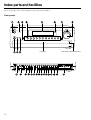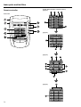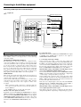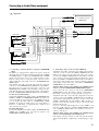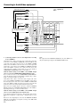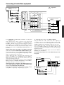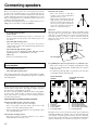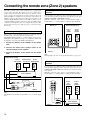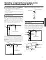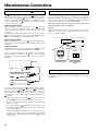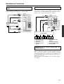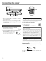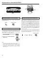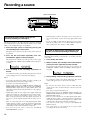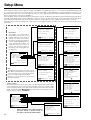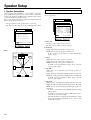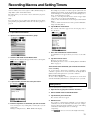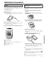
1
Contents AV Receiver Before using 2 DTR-8.3 Instruction Manual Thank you for purchasing the AV Receiver. Please read this manual thoroughly before making connections and plugging in the unit. Following the instructions in this manual will enable you to obtain optimum performance and listening enjoyment from your new AV Receiver. Please retain this manual for future reference. Facilities and connections 10 Setup and operation 31 Remote controller 64 Appendix 82 WARNING: TO REDUCE THE RISK OF FIRE OR ELECTRIC SHOCK, DO NOT EXPOSE THIS APPLIANCE TO RAIN OR MOISTURE. CAUTION: TO REDUCE THE RISK OF ELECTRIC SHOCK, DO NOT REMOVE COVER (OR BACK). NO USER-SERVICEABLE PARTS INSIDE. REFER SERVICING TO QUALIFIED SERVICE PERSONNEL. WARNING AVIS RISK OF ELECTRIC SHOCK DO NOT OPEN RISQUE DE CHOC ELECTRIQUE NE PAS OUVRIR The lightning flash with arrowhead symbol, within an equilateral triangle, is intended to alert the user to the presence of uninsulated “dangerous voltage” within the product’s enclosure that may be of sufficient magnitude to constitute a risk of electric shock to persons. The exclamation point within an equilateral triangle is intended to alert the user to the presence of important operating and maintenance (servicing) instructions in the literature accompanying the appliance. Important Safeguards 1. Read Instructions – All the safety and operating instructions should be read before the appliance is operated. 2. Retain Instructions – The safety and operating instructions should be retained for future reference. 3. Heed Warnings – All warnings on the appliance and in the operating instructions should be adhered to. 4. Follow Instructions – All operating and use instructions should be followed. 5. Cleaning – Unplug the appliance from the wall outlet before cleaning. The appliance should be cleaned only as recommended by the manufacturer. 6. Attachments – Do not use attachments not recommended by the appliance manufacturer as they may cause hazards. 7. Water and Moisture – Do not use the appliance near water –for example, near a bath tub, wash bowl, kitchen sink, or laundry tub; in a wet basement; or near a swimming pool; and the like. 8. Accessories – Do not place the appliance on an unstable cart, stand, tripod, bracket, or table. The appliance may fall, causing serious injury to a child or adult, and serious damage to the appliance. Use only with a cart, stand, tripod, bracket, or table recommended by the manufacturer, or sold with the appliance. Any mounting of the appliance should follow the manufacturer’s instructions, and should use a mounting accessory PORTABLE CART WARNING recommended by the manufacturer. 9. An appliance and cart combination should be moved with care. Quick stops, excessive force, and uneven surfaces may cause the S3125A appliance and cart combination to overturn. 10. Ventilation – Slots and openings in the cabinet are provided for ventilation and to ensure reliable operation of the appliance and to protect it from overheating, and these openings must not be blocked or covered. The openings should never be blocked by placing the appliance on a bed, sofa, rug, or other similar surface. The appliance should not be placed in a built-in installation such as a bookcase or rack unless proper ventilation is provided. There should be free space of at least 20 cm (8 in.) and an opening behind the appliance. 11. Power Sources – The appliance should be operated only from the type of power source indicated on the marking label. If you are not sure of the type of power supply to your home, consult your appliance dealer or local power company. 12. Grounding or Polarization – The appliance may be equipped with a polarized alternating current line plug (a plug having one blade wider than the other). This plug will fit into the power outlet only one way. This is a safety feature. If you are unable to insert the plug fully into the outlet, try reversing the plug. If the plug should still fail to fit, contact your electrician to replace your obsolete outlet. Do not defeat the safety purpose of the polarized plug. 2 13. Power-Cord Protection – Power-supply cords should be routed so that they are not likely to be walked on or pinched by items placed upon or against them, paying particular attention to cords at plugs, convenience receptacles, and the point where they exit from the appliance. 14. Outdoor Antenna Grounding – If an outside antenna or cable system is connected to the appliance, be sure the antenna or cable system is grounded so as to provide some protection against voltage surges and built-up static charges. Article 810 of the National Electrical Code, ANSI/NFPA 70, provides information with regard to proper grounding of the mast and supporting structure, grounding of the lead-in wire to an antennadischarge unit, size of grounding conductors, location of antenna-discharge unit, connection to grounding electrodes, and requirements for the grounding electrode. See Figure 1. 15. Lightning – For added protection for the appliance during a lightning storm, or when it is left unattended and unused for long periods of time, unplug it from the wall outlet and disconnect the antenna or cable system. This will prevent damage to the appliance due to lightning and power-line surges. 16. Power Lines – An outside antenna system should not be located in the vicinity of overhead power lines or other electric light or power circuits, or where it can fall into such power lines or circuits. When installing an outside antenna system, extreme care should be taken to keep from touching such power lines or circuits as contact with them might be fatal. 17. Overloading – Do not overload wall outlets, extension cords, or integral convenience receptacles as this can result in a risk of fire or electric shock. 18. Object and Liquid Entry – Never push objects of any kind into the appliance through openings as they may touch dangerous voltage points or short-out parts that could result in a fire or electric shock. Never spill liquid of any kind on the appliance. 19. Servicing – Do not attempt to service the appliance yourself as opening or removing covers may expose you to dangerous voltage or other hazards. Refer all servicing to qualified service personnel. 20. Damage Requiring Service – Unplug the appliance form the wall outlet and refer servicing to qualified service personnel under the following conditions: A. When the power-supply cord or plug is damaged, B. If liquid has been spilled, or objects have fallen into the appliance, C. If the appliance has been exposed to rain or water, D. If the appliance does not operate normally by following the operating instructions. Adjust only those controls that are covered by the operating instructions as an improper adjustment of other controls may result in damage and will often require extensive work by a qualified technician to restore the appliance to its normal operation, E. If the appliance has been dropped or damaged in any way, and F. When the appliance exhibits a distinct change in performance – this indicates a need for service. 21. Replacement Parts – When replacement parts are required, be sure the service technician has used replacement parts specified by the manufacturer or have the same characteristics as the original part. Unauthorized substitutions may result in fire, electric shock, or other hazards. 22. Safety Check – Upon completion of any service or repairs to the appliance, ask the service technician to perform safety checks to determine that the appliance is in proper operation condition. 23. Wall or Ceiling Mounting – The appliance should be mounted to a wall or ceiling only as recommended by the manufacturer. 24. Heat – The appliance should be situated away from heat sources such as radiators, heat registers, stoves, or other appliances (including amplifiers) that produce heat. 25. Liquid Hazards – The appliance shall not be exposed to dripping or splashing and no objects filled with liquids, such as vases shall be placed on the appliance. FIGURE 1: EXAMPLE OF ANTENNA GROUNDING AS PER NATIONAL ELECTRICAL CODE, ANSI/NFPA 70 ANTENNA LEAD IN WIRE GROUND CLAMP ANTENNA DISCHARGE UNIT (NEC SECTION 810-20) ELECTRIC SERVICE EQUIPMENT GROUNDING CONDUCTORS (NEC SECTION 810-21) GROUND CLAMPS NEC – NATIONAL ELECTRICAL CODE S2898A POWER SERVICE GROUNDING ELECTRODE SYSTEM (NEC ART 250, PART H) Precautions 1. Recording Copyright Recording of copyrighted material for other than personal use is illegal without permission of the copyright holder. 2. AC Fuse The fuse is located inside the chassis and is not user-serviceable. If power does not come on, contact your Onkyo authorized service station. 3. Care From time to time you should wipe the front and rear panels and the cabinet with a soft cloth. For heavier dirt, dampen a soft cloth in a weak solution of mild detergent and water, wring it out dry, and wipe off the dirt. Following this, dry immediately with a clean cloth. Do not use rough material, thinners, alcohol or other chemical solvents or cloths since these could damage the finish or remove the panel lettering. 4. Power WARNING BEFORE PLUGGING IN THE UNIT FOR THE FIRST TIME, READ THE FOLLOWING SECTION CAREFULLY. The voltage of the available power supply differs according to country or region. Be sure that the power supply voltage of the area where this unit will be used meets the required voltage (e.g., AC 230 V, 50 Hz or AC 120 V, 60 Hz) written on the rear panel. For U.S. models Note to CATV system installer: This reminder is provided to call the CATV system installer’s attention to Section 820-40 of the NEC which provides guidelines for proper grounding and, in particular, specifies that the cable ground shall be connected to the grounding system of the building, as close to the point of cable entry as practical. For Canadian models NOTE: THIS CLASS B DIGITAL APPARATUS COMPLIES WITH CANADIAN ICES-003. For models having a power cord with a polarized plug: CAUTION: TO PREVENT ELECTRIC SHOCK, MATCH WIDE BLADE OF PLUG TO WIDE SLOT, FULLY INSERT. Modèle pour les Canadien REMARQUE: CET APPAREIL NUMÉRIQUE DE LA CLASSE B EST CON-FORME À LA NORME NMB-003 DU CANADA. Sur les modèles dont la fiche est polarisée: ATTENTION: POUR ÉVITER LES CHOCS ÉLECTRIQUES, INTRODUIRE LA LAME LA PLUS LARGE DE LA FICHE DANS LA BORNE CORRESPONDANTE DE LA PRISE ET POUSSER JUSQU’AU FOND. FCC INFORMATION FOR USER CAUTION: The user changes or modifications not expressly approved by the party responsible for compliance could void the user’s authority to operate the equipment. NOTE: This equipment has been tested and found to comply with the limits for a Class B digital device, pursuant to Part 15 of the FCC Rules. These limits are designed to provide reasonable protection against harmful interference in a residential installation. This equipment generates, uses and can radiate radio frequency energy and, if not installed and used in accordance with the instructions, may cause harmful interference to radio communications. However, there is no guarantee that interference will not occur in a particular installation. If this equipment does cause harmful interference to radio or television reception, which can be determined by turning the equipment off and on, the user is encouraged to try to correct the interference by one or more of the following measures: • Reorient or relocate the receiving antenna. • Increase the separation between the equipment and receiver. • Connect the equipment into an outlet on a circuit different from that to which the receiver is connected. • Consult the dealer or an experienced radio/TV technician for help. 3 Contents Before using Important Safeguards ......................................... 2 Precautions ......................................................... 3 Contents .............................................................. 4 Features ............................................................... 6 Supplied accessories ......................................... 7 Before using this unit ......................................... 7 Connecting the power cord .............................................. 7 Using the remote controller .............................................. 7 Setting up the remote controller ....................... 8 Insert batteries .................................................................. 8 Characterizing the remote controller ............................... 8 Touch the screen to start ................................................... 9 Facilities and connections Index parts and facilities .................................. 10 Front panels .................................................................... 10 Front panel display ......................................................... 12 Rear panels ..................................................................... 13 Remote controller ........................................................... 14 Connecting to Audio/Video equipment .......... 16 Connecting your audio components .............................. 17 Connecting your video components .............................. 18 Connecting speakers ....................................... 22 Ideal speaker configuration ............................................ 22 Minimum speaker configuration for surround sound playback .................................................................. 22 Speaker placement .......................................................... 22 Connecting speakers ....................................................... 23 Using the speaker labels ................................................. 23 Connecting antennas ....................................... 24 Assembling the AM loop antenna .................................. 24 Connecting the AM antenna cable ................................. 24 Connecting the included antennas ................................. 24 Connecting an FM outdoor antenna ............................... 25 Connecting an AM outdoor antenna .............................. 25 Directional linkage ......................................................... 25 Connecting the antenna cable to the 75/300 Ω antenna adapter (Australian model only) ............................. 25 Connecting the remote zone (Zone 2) speakers ... 26 Connecting the power ...................................... 30 Turning on the power ..................................................... 30 Turning on the power from the remote controller ......... 30 To change the display of the input source from TAPE to MD ..... 30 Setup and operation Enjoying music or videos with the DTR-8.3 .... 31 Basic operation ............................................................... 31 Changing the listening mode .......................................... 32 Switching the display ..................................................... 33 Temporarily turning off the sound ................................. 33 Adjusting the bass and treble ......................................... 33 Listening with headphones ............................................. 33 Adjusting the brightness of the front display ................ 34 Temporarily changing the speaker output levels ........... 34 Using the sleep time (remote controller only) ............... 34 Changing the audio mode ............................................... 35 Enjoying the multichannel output .................................. 35 Listening to Radio Broadcasts ........................ 36 Tuning into a radio station ............................................. 36 Listening to a stereo radio station (FM mode) .............. 36 Presetting a radio station ................................................ 37 Selecting a preset radio station ...................................... 37 Erasing a preset radio station ......................................... 37 Recording a source .......................................... 38 To record the input source signal you are currently watching or listening to .......................................... 38 To record an input source signal different from that you are currently watching or listening to ..................... 38 Recording the video from one source and the audio from another ..................................................................... 39 Enjoying music or videos in the remote zone ..... 40 Using the buttons on the DTR-8.3 ................................. 40 Selecting an input source using the remote controller .. 41 Adjusting the volume for the remote zone .................... 41 Setup Menu........................................................ 42 Navigating through the Setup Menu .............................. 43 When using the ZONE 2 OUT terminals ...................... 26 When using the SURR BACK/ZONE 2 SPEAKERS terminals .................................................................. 26 When using the SURR BACK/ZONE 2 PRE OUT terminals .................................................................. 26 Hardware Setup ................................................. 44 Operating components not reached by the remote controller signals (IR IN/OUT) ....... 27 Speaker Setup ................................................... 46 If the remote controller signal does not reach the DTR-8.3 remote sensor .......................................................... 27 If the remote controller signal does not reach other components ............................................................. 27 Miscellaneous Connections ............................ 28 Connections for remote control ( ) ............................ 28 Connecting the power cords from other devices ........... 28 4 RS 232 port ..................................................................... 28 Connecting to devices with analog multi channel output ....... 29 Connecting auxiliary power amplifier ........................... 29 Connecting to an external device with 12V TRIGGER terminal ................................................................... 29 0. Hardware Setup Menu ............................................. 44 0-1. Speaker Impedance Sub-menu ............................... 44 0-2. Surr Back/Zone 2 Sub-menu .................................. 45 0-3. IR IN Setup Sub-menu ............................................ 45 1. Speaker Setup Menu ................................................ 46 1-1. Speaker Config Sub-menu ...................................... 46 1-2. Speaker Distance Sub-menu ................................... 47 1-3. Level Calibration Sub-menu ................................... 48 Input Setup ........................................................ 49 2. Input Setup Menu ..................................................... 49 2-1. Digital Setup Sub-menu (When NET AUDIO is not selected as the input source) ................................... 49 Contents 2-2. Multichannel Setup Sub-menu (When NET AUDIO is not selected as the input source) ............................. 50 2-3. Video Setup Sub-menu ........................................... 51 2-4. Character Input Sub-menu ...................................... 51 2-5. IntelliVolume Sub-menu ......................................... 52 2-6. Listening Mode Preset Sub-menu .......................... 52 2-7. 12V Trigger Setup sub-menu .................................. 52 Audio Adjust ...................................................... 56 3. Audio Adjust Menu .................................................. 56 3-1. Tone Control Sub-menu .......................................... 56 3-2. Surround Speakers Sub-menu ................................ 56 3-3. Sound Effect Sub-menu .......................................... 57 3-4. Delay Sub-menu ...................................................... 57 3-5. LFE Level Sub-menu .............................................. 58 3-6. Mono Sub-menu ...................................................... 58 3-7. Theater-Dimensional Sub-menu ............................. 58 3-8. Surround Sub-menu ................................................ 59 3-9. THX Sub-menu ....................................................... 60 3-10. 3-11. 3-12. 3-13. 3-14. 3-15. Mono Movie/ Enhanced 7/Orchestra/Unplugged/Studio Mix /TV Logic Sub-menu ...................................................... 60 Preference ......................................................... 62 4. Preference Menu ....................................................... 62 4-1. Volume Setup Sub-menu ......................................... 62 4-2. Headphones Level Sub-menu ................................. 63 4-3. OSD Setup Sub-menu ............................................. 63 4-4. OSD Position Sub-menu ......................................... 63 Organizing macros and timers into groups .................... 76 Using the remote controller with Radio Frequency (USA & Canadian models only) .................. 77 Changing the remote controller’s RF IR Settings ......... 77 Choosing Another Channel ............................................ 78 Additional information ..................................... 79 ChadEdit ......................................................................... 79 Optional recharging dock (USA and Canadian models only) ........................................................................ 79 FAQ ..................................................................... 80 Overview of Symbols ....................................... 81 Appendix Troubleshooting guide ..................................... 82 POWER .......................................................................... 82 SPEAKERS .................................................................... 82 FM/AM TUNER ............................................................. 82 VIDEO and AUDIO ....................................................... 83 OTHER ........................................................................... 83 REMOTE CONTROLLER ............................................ 84 If one of the messages shown below appears ................ 85 Specifications ................................................... 86 Remote controller Using the Remote Controller ........................... 64 Adjust the Settings ......................................................... 64 Working with Modes ...................................................... 65 Selecting a Device .......................................................... 66 Define the Brand of Your Device ..................... 67 Define the Brand of Your Device ................................... 67 Defining brands by searching ........................................ 69 Programming Buttons ...................................... 70 Programming control panel buttons ............................... 70 Programming device items ............................................. 71 Programming direct-access and Left/Right Buttons ..... 71 Labeling Buttons and Menu Items .................. 72 Labeling a button ............................................................ 72 Labeling a menu item ..................................................... 72 Adding and Moving Devices ............................ 73 Adding devices ............................................................... 73 Adding macros ................................................................ 73 Moving menu items ........................................................ 73 Delete and restore ............................................ 74 Delete .............................................................................. 74 Restore ............................................................................ 74 Recording Macros and Setting Timers ........... 75 Recording macros ........................................................... 75 Editing macros ................................................................ 75 Setting timers .................................................................. 76 5 Features Amplifier Features Other Performance Features ■ 110 Watts minimum of continuous RMS power to ■ IntelliVolume ■ ■ ■ ■ ■ each of the seven channels into 8 W from 20 Hz to 20 kHz with no more than 0.08 % THD (FTC rated) 7.1 Channel Amplifier Wide Range Amplifier Technology (WRAT) Linear Optimum Gain Volume Circuitry 192 kHz/24 Bit D/A Converters (except for Surround Back L/R) Powered Zone 2 and 12V Trigger Audio/Video Features ■ THX® Surround EX® ■ THX Select Certified ■ Character Input ■ Backlit/preprogrammed & learning remote with ■ ■ ■ ■ * Manufactured under license from Dolby Laboratories. ■ Dolby®* Digital, Dolby Pro Logic II, Dolby Digital ■ ■ ■ ■ ■ ■ ■ ■ ■ EX DTS, DTS-ES Discrete 6.1, DTS-ES Matrix 6.1, DTS Neo:6, and DTS 96/24 Theater-DimensionalTM Virtual Surround Mode Non-Scaling Configuration Onscreen displays (Basic Menu/Advanced Menu) Composite to S-Video Conversion 6 S-Video Inputs/3 Outputs Crossover Adjustment 7 Assignable Digital Inputs (4 optical/3 coaxial), 2 outputs, and 1 Digital Input (optical) Pre Out Terminals for Front L/R, Center, Surround L/R, Surround back L/R or Zone 2 L/R and Subwoofer FM/AM Tuner Features ■ 40 FM/AM random presets ■ FM auto tuning 6 LED display VLSC (Vector Linear Shaping Circuitry) for L/ C/R channels (Other than USA, Canadian and Australian models) Net-Tune Function with MP3/WAV/WMA Decoding Ethernet cable plug-In Capability Unique and fully customizable universal touchscreen remote controller • • • • • • “Dolby,” “Pro Logic,” “Surround EX” and the double-D symbol are trademarks of Dolby Laboratories. “Theater-Dimensional” is a trademark of Onkyo Corporation. “NET-TUNE” is a trademark of Onkyo Corporation. Lucasfilm THX and THX are trademarks or registered trademarks of THX Ltd. Re-Equalization and the “Re-EQ” logo are trademarks of THX Ltd. “DTS,” “DTS-ES Extended Surround” and “Neo:6” are trademarks of Digital Theater Systems, Inc. Windows Media, and the Windows logo are trademarks, or registered trademarks of Microsoft Corporation in the United States and/or other countries. • Intel and Pentium are registered trademarks of Intel Corporation. • MPEG Layer-3 audio coding technology licensed from Fraunhofer IIS and THOMSON multimedia. • “XiVA” is a registered trademark of Imerge Limited. • Xantech is a registered trademark of Xantech Corporation. • Niles is a registered trademark of Niles Audio Corporation. The alphabet displayed at the end of the product name found in catalogs and on the packages represents the color of this receiver. Though the color varies, the specifications and operations are the same. THX Select Before any home theatre component can be THX Select certified, it must pass a rigorous series of quality and performance tests. Only then can a product feature the THX Select logo, which is your guarantee that the Home Theatre products you purchase will give you superb performance for many years to come. THX Select requirements define hundreds of parameters, including power amplifier performance, and pre-amplifier performance and operation for both digital and analog domains. THX Select receivers also feature proprietary THX technologies (e.g., THX Mode, see page 55) which accurately translate film soundtracks for home theater playback. Supplied accessories Check that the following accessories are supplied with the DTR-8.3. Surround Back Right Surround Back Right Zone 2 Right Zone 2 Right Australian model only Surround Back Right Surround Back Right Zone 2 Right Zone 2 Right Center Center Surround Right Surround Right Surround Left Surround Left Surround Back Left Surround Back Left Zone 2 Left Zone 2 Left Surround Back Left Surround Back Left Zone 2 Left Zone 2 Left Center Center Surround Right Surround Right Surround Left Surround Left Front Right Front Right SP-B / Zone 2 Right SP-B / Zone 2 Right Front Left Front Left SP-B / Zone 2 Left SP-B / Zone 2 Left 1 Front Right Front Right SP-B / Zone 2 Right SP-B / Zone 2 Right FM indoor antenna × 1 Front Left Front Left SP-B / Zone 2 Left SP-B / Zone 2 Left AM loop antenna × 1 Remote controller × 1 Batteries (AA, R6 or UM-3) × 4 RS232 cable for PC connection × 1 2 3 Speaker Cable Speaker cable label × 1 (See page 23.) Power cord × 1 75/300 Ω antenna adapter × 1 Before using this unit Connecting the power cord Using the remote controller Plug the supplied power cord into this AC INLET. • Do not use a power cord other than the one supplied with the DTR-8.3. The power cord supplied is designed for use with the DTR-8.3 and should not be used with any other device. • Never have the power cord disconnected from the DTR-8.3 while the other end is plugged into the wall outlet. Doing so may cause an electric shock. Always connect by plugging into the wall outlet last and disconnect by unplugging from the wall outlet first. Point the remote controller toward the remote control sensor. The Standby indicator lights up when the unit receives a signal from the remote controller. Remote control sensor DTR-8.3 Standby indicator 30˚ 30˚ Approx. 16 feet AC INLET Power cord (supplied) DO NOT connect the power cord at this time. Notes: • Make sure that the remote control sensor is not subject to strong light such as direct sunlight or inverted fluorescent light for it may prevent proper operation of the remote controller. • Using another remote controller in the same room or using the DTR-8.3 near equipment that uses infrared rays may cause operational interference. • Do not put objects on the remote controller. Its buttons may be pressed by mistake and drain the batteries. • Make sure the audio rack doors do not have colored glass. Placing the DTR-8.3 behind such doors may prevent proper remote controller operation. • If there is any obstacle between the remote controller and the remote control sensor, the remote controller will not operate. 7 Setting up the remote controller Insert batteries 1. Slide the battery cover off the back of the remote controller. Characterizing the remote controller Sending eye/Learning eye Direct-access buttons Touchscreen Contrast dial Left/Right buttons Backlight button 2. Insert 4 AA batteries (included in package) as indicated on the bottom of the battery compartment. The intelligent remote controller can be used for all devices that understand infrared remote controller signals. Its easy-to-use touchscreen and its intuitive interface makes it a perfect remote controller for every user. The remote controller is completely customizable and programmable. You can add devices and functions, relabel buttons, record macros and set timers. To make the remote controller your universal remote controller, it is designed to learn from existing remote controllers. Direct-access buttons The buttons labeled MUTE, CH, and VOL are direct-access buttons. The direct-access buttons make these frequently used functions available even when the touchscreen is off. You can program them so that they always operate the same components — for example, the TV. Or, you can program them to operate different devices at different times. 3. Slide the battery cover back on. After a few seconds, the remote controller starts up automatically and beeps twice to indicate that it is ready to use. When batteries are running low, the Low Battery icon blinks at the center top of the display. Replace the batteries as soon as possible to ensure perfect performance. Note: • The remote controller retains all settings when batteries have run out or when you replace them. You will only have to reset the clock. • Do not mix new batteries with old batteries or different kinds of batteries. • To avoid corrosion, remove the batteries if the remote controller is not to be used for a long time. • Remove dead batteries immediately to avoid damage from corrosion. If the remote controller does not operate smoothly, replace both the batteries at the same time. Serial port Reset button Battery cover 8 Setting up the remote controller Touch the screen to start To turn on the screen, tap it gently with your finger. To use the touchscreen, simply tap the images you see on the screen. There’s no need to turn the screen off — it shuts off automatically to save power. 6. Left and Right buttons The Left and Right buttons change function depending on the device the remote controller is operating. The current function is displayed on the touchscreen right above the button. The function can be either an IR (infrared) command that is transmitted, or a jump to a specific device page. The Left button function Be sure to read the manual for important information about care and use of the touchscreen. Fresh out of the box, the remote controller is already set up to work with popular components made by Integra/Onkyo. 7. Remote controller icon When you send a command, the remote controller icon shows transmitting signals 1 7 8. Scroll button Most devices have more than one control panel. You can scroll through these control panels using and . The panel number on the left bottom of the screen indicates the panel number and the total number of panels, for example . 8 By touching and holding a scroll button, you go repeatedly through all the control panels of a device in a loop. – CONT + MUTE LIGHT 3 + 9 CH 9. Switch between the Home menu and the Device menu you selected prior to the Home menu. – 4 . The name of the active device is indicated on the device tab. Press and hold the icon for 3 seconds to go to the Setup menu of the remote controller. Home menu 2 The Right button function 10. Mode menu Customize the remote controller. VOL 10 5 11 11. Scroll button Display next control panel. Component’s control panel 6 When you select any component from the Home menu, the control panel shown below appears. 1 3 1. Sending eye (IR transmitter)/Learning eye Send commands to devices. For learning commands from other remote controllers. 2. Current time and day For setting the time and day, refer to “Adjust the Settings” (page 64). 3. Macro menu Execute stored lists of commands. 4. Control panel Tap buttons to select a components. 5. Panel number Shows what panel you’re seeing. 2 4 1. Home If you get lost, you can always go to the Home menu screen. Just tap Home. 2. Tap name of component to display component’s control panels. 3. You can also use the Device menu; tap to display it. 4. Tap to scroll to next panel for this component. 9 Index parts and facilities Here is an explanation of the controls and displays on the front panel of the DTR-8.3. Front panels Front door Push here to open the front door. L 10 Index parts and facilities For further operational instructions, see the pages indicated in brackets [ ]. Front panels Standby/On button [30] After plugging in the power cord, the DTR-8.3 turns on and the display lights up, the DTR-8.3 turns on and the display lights up. If pressed again, the DTR-8.3 returns to the standby state. In the standby state, the display is turned off and the DTR-8.3 cannot be operated. Standby indicator [7, 30] Lights when the DTR-8.3 is in the standby state and when a signal is received from the remote controller. Audio Selector button [35] Press to select the type of audio input signal. Input source buttons and indicators (DVD, Video 1–5, Tape, Tuner, Phono, CD, and Net Audio) [31, 36, 38, 40] Press these buttons to select the input source for the main zone. To select the input source for the remote zone (Zone 2) or recording out (Rec Out), first press the Zone 2 or Rec Out button, and then press the desired input source button. The input channel with its indicator lit red is output to Rec Out and the one with its indicator lit green is output to Zone 2. Front display Remote control sensor [7] Display button [33] Press to display information about the current input source signal. Each time you press the Display button, the screen changes to show you different information concerning the input signal. Master Volume dial [31, 35] Use to control the volume in the main zone. The volume for the remote zone (Zone 2) is independent. Upsampling indicator [57] Lights during upsampling. Pure Audio indicator [32] Lights during pure audio playback. Direct/Pure Audio button [32, 35] Press to switch between the direct and pure audio listening modes. Phones jack [33] This is a standard stereo jack for connecting stereo headphones. Zone 2 Level / buttons [41] Press to enter the mode for adjusting the volume in the remote zone (Zone 2). Rec Out/Zone 2/Off buttons [38-40] These buttons allow you to use the DTR-8.3 to output to a remote zone (Zone 2) or to another component for recording (Rec Out). Press the Rec Out button to output the audio and video signals to a recording component for recording. Press the Zone 2 button to enjoy the output from the DTR-8.3 in a different room, which is referred to as the remote zone (Zone 2). When either button is pressed, the currently selected input source for recording or outputting to the remote zone is displayed in the front panel display. If “SOURCE” is displayed, then the same input source as that selected for the main zone will be output. To select an input source, press the desired button (Rec Out or Zone 2) and then press one of the input source button within 8 seconds. That source will be output for recording or viewing in the remote zone. To set the output to the source channel, press the desired button (Rec Out or Zone 2) twice in succession. To turn off the output, press the desired button (Rec Out or Zone 2) and then press the Off button within 8 seconds. Note: The Rec Out and Zone 2 buttons use the same circuit and therefore cannot be used at the same time. When Rec Out is selected, nothing is output to Zone 2. When Zone 2 is selected, Rec Out is automatically fixed to Source. Stereo button [32] Selects for the stereo listening mode. Surround button [32] Selects for the Dolby Pro Logic II, DTS Neo:6, Dolby Digital, or DTS listening modes. THX button [32] Selects for the THX listening mode. DSP / buttons [32] Switches to the DSP (Digital Signal Processing) modes. Dimmer button [34] Press to set the brightness of the front display. There are three settings available: normal, dark, and very dark. • The brightness of the front display can also be performed using the remote controller. Memory button [37] Press to assign the radio station that you are currently tuned to a preset channel or press to delete a previously preset station. FM Mode button [36] Press to change the stereo mode from Auto to Mono and vice versa. Each time this button is pressed, the Auto indication turns on and off indicating the current mode. If you are listening to an FM radio station in stereo and the sound cuts out or there is a great deal of noise, switch from Auto to Mono. Setup button [43] Press to enter the Setup Menu. The OSD Menu will appear on the TV monitor as well as the front display on the DTR-8.3. 11 Index parts and facilities Tuning / , Preset / buttons [36, 37, 43] To tune into a radio station, press the Tuning / buttons. The tuner frequency is displayed in the front display and it can be changed in 50kHz increments for FM and 10-kHz (or 9-kHz) increments for AM. When FM is selected as the input source, you can hold down either the Tuning or button and then release it to activate the autosearch feature. It will search for a station in the direction of the button you pressed and stop when it tunes into one. When navigating through the menu settings, these buttons move the cursor up or down (or change the highlighted item). To select a radio station that was stored using the Memory button, press the Preset / buttons. When navigating through the menu settings, these buttons select the value or item that you selected with the Tuning / buttons. When you press the Setup button, the Tuning and Preset buttons become cursor buttons to be used for Setup Menu operations. Enter button [43] Press to display the screen for the item that is selected in the Setup Menu. Return button [43] When in the Setup Menu, press to go back one level. If pressed while at the Main Menu, you will exit the Setup Menu. Video 5 Input terminals [21] For connecting a video camera or game device. Front panel display Input signal path indicators Shows from which terminal the input signal is coming. Listening mode or digital input format indicators One of these indicators lights to show the format of the current input source. In addition, one of the listening mode indicators lights to indicate the current listening mode. Tuning indicators AUTO indicator Lights when receiving FM broadcasts in the stereo mode. Turns off when placed into the monaural mode. TUNED indicator Lights when a radio station is received. FM STEREO indicator Lights when an FM broadcast station is received in stereo. 12 Multi function display During normal operation, shows the current input source and volume. When the FM or AM input is selected, shows the frequency and preset number. When the DISPLAY button is pressed, shows the listening mode and input source format. However, does not show the source format when the FM or AM source is selected. Volume display Shows the volume level. SLEEP indicator Lights when the sleep timer is turned on. Index parts and facilities Rear panels DIGITAL INPUT COAX PRE OUT R VIDEO AUDIO ANTENNA L FRONT S VIDEO MONITOR OUT 1 SUB COMPONENT VIDEO SURR SPEAKERS FRONT SPEAKERS OUTPUT Y R R AV RECEIVER L MODEL NO. DTR-8.3 RATING: AC 120 V 60 Hz 8.4 A L R CENTER AM 2 OUT ZONE 2 IN DVD PB AC OUTLETS SURR 3 OPT SURR BACK/ ZONE 2 R PR L INPUT 1 FM 75 1 Y OUT VIDEO 1 FRONT MULTI CH INPUT AUDIO L 2 R R SUB L CENTER 3 PHONO OUT PR VIDEO 2 SURR 4 CD R OPT 1 L IN IN DIGITAL OUTPUT VIDEO 3 PB VIDEO 4 PR CAUTION: SPEAKER IMPEDANCE SURR BACK/ ZONE 2 SPEAKERS CENTER SPEAKER AC 120 V 60 Hz SWITCHED TOTAL 120W 1A MAX. 4 OHMS MIN. OR 6 OHMS MIN. /SPEAKER L R SEE INSTRUCTION MANUAL FOR CORRECT SETTINGS. IR A IN ZONE 2 AC INLET 12 V TRIGGER OUT RS232 TAPE 2 GND INPUT 2 Y IN OUT SURR BACK ETHERNET [NET-TUNE] PB IN OUT IN R AUDIO L R AUDIO L VIDEO B REMOTE CONTROL S VIDEO For more information regarding connection procedures, see pages indicated in brackets [ ]. DIGITAL INPUT/OUTPUT [17-21] These jacks are for connecting components with digital input and output capabilities. To connect a CD player, see page 17; to connect an MD or CD recorder, see page 17; to connect a DAT deck, see page 17; to connect a DVD player, see page 18; to connect a DVD recorder, see page 20; and to connect a digital satellite tuner, see page 21. PRE OUT [23, 26, 29] To use the DTR-8.3 as a preamplifier, connect a power amplifier to this jack. ANTENNA [24, 25] These jacks are for connecting the FM indoor antenna and AM loop antenna that are supplied with the DTR-8.3. MULTI CH INPUT [29] This connector is for connecting components with a multi-channel output. PHONO/CD/TAPE AUDIO IN/OUT [17] These connectors are for connecting to the audio input and output jacks on audio components. To connect a turntable, see page 17; to connect a CD player, see page 17; and to connect a cassette tape deck, MD recorder, or CD recorder, see page 17. DVD/VIDEO1-4 IN/OUT [18-21] These connectors are for connecting to the video input and output jacks on video components. To connect a DVD player, see page 18; to connect a DVD recorder, see page 20; to connect a VCR, see page 19; and to connect a Satellite tuner, see page 21. ZONE2 AUDIO/VIDEO OUT [26] These jacks are for connecting the components that will be used in the remote zone (Zone 2). COMPONENT VIDEO INPUT1/2 [18-20] These connectors are for connecting to the component video outputs of video components that have them. To connect a DVD player, see page 18; to connect a DVD recorder, see page 20; and to connect a Satellite tuner, see page 21. MONITOR OUT VIDEO/S VIDEO [19] These jacks are for connecting to the video input jacks on television monitors or projectors. RS232 [28] This connector is for connecting to the RS-232 port of an external device. COMPONENT VIDEO OUTPUT [19] These jacks are for connecting to the component video input jacks on television monitors or projectors. IR IN/OUT [27] These connectors are for connecting the remote sensor of a multiroom kit (sold separately). ETHERNET (NET-TUNE) This connector is for connecting to an Ethernet network. [28] This jack is for connecting other Onkyo components equipped with the same terminal. SPEAKERS [23, 26] These terminals are for connecting the speakers. AC OUTLETS [28] This AC outlet is provided to plug in the power cord from another component. 12V TRIGGER OUT ZONE 2 A/B [29] These connectors are used to connect to the 12V TRIGGER IN terminal of a component in the remote zone (Zone 2) if one has one. AC INLETS [7] This connector is for connecting the supplied power cord. 13 Index parts and facilities AV Amp (Select AV Amp on the Home menu) (page 1/4) Remote controller Home menu – CONT + MUTE LIGHT + CH – VOL (page 2/4) (page 3/4) (page 4/4) 14 Index parts and facilities For details on how to use the remote controller, refer to “Using the remote controller” (page 64). Select AV Amp in the Home menu to display the operation buttons. CONT +/– buttons If the display stays blank or becomes black, adjust the contrast dial on the left side. LIGHT button Press to turn on the backlight for brighter display when you use the DTR-8.3 in the dark room. The backlight shuts off automatically after a few seconds to save power. Note: You can choose to activate the backlight automatically when you activate the remote controller. (For details about the settings, see “Second setup panel” under “Adjust the Settings” on page 64.) AV amp button Before operating the DTR-8.3, press this button. ZONE 2 button [41] Press to perform operations on the remote zone. Net A button Press to listen to the Net Audio. MUTE button [33] Press to activate the mute function. CH +/– button [37, 41] When AV Amp is selected, for selecting a tuner preset channel. VOL / buttons [31, 35, 41] When AV Amp is selected, for adjusting the volume. When Zone 2 is selected, for adjusting the volume in the Zone 2. First operation menu (page 1/4) ON button [30, 41] Press to turn on the DTR-8.3. OFF button [30] Press to place the DTR-8.3 in the standby state. Be aware that pressing the STANDBY button only places the DTR8.3 in standby and does not turn the power completely off. LISTEN button [32] For displaying the 2/4 listening mode page. SETUP button For displaying the 3/4 setup operation page. Input Selector buttons [31, 36, 41] Select an input source for the main zone. Audio Sel button [35] Press to select the audio input signal. Second operation menu (page 2/4) Listening mode buttons [35] You can select a listening mode. Display button [33] For changing the display in the front display. Re-EQ button [57, 60] Depending on the listening mode, you can turn the Re-EQ function on or off. Third operation menu (page 3/4) Setup button [43] Press to display the Setup Menu on the TV screen and in the display. Press again to exit the menu. Return button [43] Press to enter the selected setting and return to the previous menu. Test button [48] This button is used to set the speaker output levels. Use this button in conjunction with the LEVEL / and CH SEL buttons to calibrate the speakers levels without entering the Setup Menu. Dim button [34] Adjusts the display brightness. There are three settings available: normal, dark and very dark. / / / , Enter buttons [43] When in the Setup Menu, press the upper and lower arrow buttons to select an item, press the right and left arrow buttons to select parameter values or modes, and press the Enter button to advance to the next item. Sleep button [34] Press to set the sleep function. The SLEEP button enables you to set the DTR-8.3 to turn off automatically after a specified time period. +/– buttons [34, 48] Select the speaker whose volume is to be adjusted using the CH Sel button and adjust the volume using the +/– buttons. SP A/B buttons These buttons are not used with the DTR-8.3. CH Sel button [34] Press to select a speaker channel when adjusting the speaker level. FM/AM buttons [36] Select the tuner band. Not used with the DTR-8.3. The buttons can be used to do direct tuning or tune in a radio station on some Onkyo products. 15 Connecting to Audio/Video equipment • Be sure to always refer to the instructions that came with the component that you are connecting. • Do not plug in the power cord until all connections have been properly made. • For input jacks, red connectors (marked R) are used for the right channel, white connectors (marked L) are used for the left channel, and yellow connectors (marked V) are used for video connection. • Insert all plugs and connectors securely. Improper connections can result in noise, poor performance, or damage to the equipment. Improper connection Cables are depicted in the connection diagrams as shown below. Left (white) L Audio connection cable Right (red) R PR PR PB PB Y Y Component video connection cable Video connection cable Inserted completely • Do not bind audio/video connection cables with power cords and speaker cables. Doing so may adversely affect the picture and sound quality. • The optical digital jacks are all of the shutter-type construction. Connect an optical cable by first making sure the cable is oriented correctly and then inserting it into the jack pushing the shutter lid inwards. Rear optical jack 16 Front optical jack S video connection cable Coaxial cable Optical cable Connecting to Audio/Video equipment Here is an explanation of typical ways to connect various components to the DTR-8.3. There are many ways that any one component can be connected, and it is up to you to decide which method best fits your situation. The directions given here are only one option and should only be thought of as such. It is best to fully understand the nature of each connector and terminal as well as those of your components and their features to ascertain which method of connection is best. : Signal flow Ground wire (earth) Digital audio output (optical) R (red) DIGITAL INPUT COAX PRE OUT R Analog audio output ANTENNA L FRONT 1 Digital audio input (optical) SUB L (white) CENTER AM 2 SURR 2. Turntable (PH) 3 OPT SURR BACK/ ZONE 2 R L FM 75 1 3. Cassette tape deck, MD recorder, DAT deck, or CD recorder (TAPE) FRONT MULTI CH INPUT AUDIO 2 R L SUB R L CENTER 3 PHONO R (red) Analog audio output SURR R (red) 4 CD R OPT 1 L OUT L (white) SURR BACK Analog audio input L (white) TAPE 2 GND DIGITAL OUTPUT IN R AUDIO 1. CD player (CD) L R (red) Analog audio output Digital audio output (optical) L (white) Connecting your audio components Below is an example of how you can connect your audio components to the DTR-8.3. Refer to the diagram above for the following connection examples. AUDIO IN/OUT These are the analog audio inputs and outputs. There are eight audio inputs and three audio outputs on the rear panel. The audio inputs and outputs require RCA-type connectors. DIGITAL INPUT/OUTPUT On the rear panel of the DTR-8.3, there are three coaxial digital inputs, four optical digital inputs, and two optical digital output. To the digital inputs, connect CD players, LD players, DVD players, or other digital source component. To the digital output, connect MD recorders, CD recorders, DAT decks, or other similar components. • Since an analog connection must be made when using REC OUT or ZONE 2, make sure that the connection to the input source is not digital only, but analog as well. • When using an optical input or output jack, always use an optical fiber cable. 1. Connecting a compact disc player (CD) Using an RCA audio cable, connect the output jacks of the compact disc player to the CD AUDIO jacks of the DTR-8.3. Make sure that you properly connect the left channel to the L jack and the right channel to the R jack. If the compact disc player has a digital output, connect it to either the DIGITAL INPUT COAX jack or DIGITAL INPUT OPT jack of the DTR-8.3 depending on the type of connector on the compact disc player. With the initial settings of the DTR-8.3, the CD input source is set for digital input at the OPT 1 jack. If the digital connection is made to a different jack, this must be changed at Setup Menu → Input Setup → Digital Setup (see page 49). 2. Connecting a turntable (PHONO) Using an RCA audio cable, connect the output jacks of the turntable to the PHONO audio jacks of the DTR-8.3. Make sure that you properly connect the left channel to the L jack and the right channel to the R jack. Note: The DTR-8.3 is designed for use with moving magnet cartridges. For proper operation, connect a ground (or earth) wire to the GND terminal. For some turntables, however, connecting the ground wire may cause increased noise, and in such a case, a ground wire is not necessary and should not be connected. 3. Connecting a cassette tape deck, MD recorder, DAT deck, or CD recorder (TAPE) Using RCA audio cables, connect the output jacks (PLAY) of the device to the TAPE AUDIO IN jacks of the DTR-8.3 and connect the input jacks (REC) of the device to the TAPE AUDIO OUT jacks of the DTR-8.3. Make sure that you properly connect the left channels to the L jacks and the right channels to the R jacks. If the device has a digital output, connect it to either the DIGITAL INPUT COAX jack or DIGITAL INPUT OPT jack of the DTR-8.3 depending on the type of connector on the device. With the initial settings of the DTR-8.3, the TAPE input source is set for digital input at the OPT 2 jack. If the digital connection is made to a different jack, this must be changed at Setup Menu → Input Setup → Digital Setup (see page 49). If the device has a digital input, connect it to the DIGITAL OUTPUT OPT 1 or 2 jack of the DTR-8.3 for digital recording of the REC OUT signal from the DTR-8.3. Note: The output from the DIGITAL OUTPUT jack of the DTR-8.3 is only the digital signal input to the DIGITAL INPUT jack. 17 Connecting to Audio/Video equipment Connecting a DVD Player with 5.1-Channel Output : Signal flow Digital audio output (coaxial) R (red) Analog audio output DIGITAL INPUT COAX PR R TENNA VIDEO AUDIO FRONT S VIDEO MONITOR OUT 1 COMPONENT VIDEO OUTPUT Y L (white) Video output L R SUB AM 2 OUT ZONE 2 IN DVD PB SURR 3 OPT SURR BACK/ ZONE 2 PR R FM 75 1 S Video output INPUT 1 Y OUT VIDEO 1 FRONT 2 IN PB OUT PR R UDIO L 4. DVD player (DVD) SUB 3 PHONO VIDEO 2 SURR 4 CD R OPT 1 OUT IN SURR BACK IN GND L UDIO VIDEO 3 PB VIDEO 4 PR TAPE 2 DIGITAL OUTPUT INPUT 2 Y IN IN R AUDIO L VIDEO S VIDEO Y PB PR Component video output Connecting your video components Below is an example of how you can connect your video components to the DTR-8.3. Refer to the diagram above for the following connection examples. COMPONENT VIDEO INPUT/OUTPUT For DVD players or other devices that have component video connectors, the DTR-8.3 has two banks of component video input connectors (Y, PB, PR) for direct component video input. The DTR8.3 also has one bank of component video output connectors for direct component video output to the matrix decoder of a television, projector, or other display device. By sending the pure component video signal directly, the signal forgoes the extra processing that normally would degrade the image. The result is vastly increased image quality, with incredibly lifelike colors and crisp detail. VIDEO IN/OUT These are the video inputs and outputs. On the rear panel, there are five video inputs and two video outputs and each one includes both composite video and S video configurations. Connect VCRs, VTRs, LD players, DVD players, and other video components to the video inputs. Connect VCRs, VTRs, and other recording components to the video outputs to make video recordings. • When connecting a VCR or other video component, make sure you connect its audio and video leads to the same bank (e.g., both to VIDEO 3). • The VIDEO 5 inputs are located on the front panel. The flow of the video signals is as follows: Signals that comes in from VIDEO and S VIDEO INPUT are output to VIDEO, S VIDEO and COMPONENT VIDEO. However, signals that comes in from COMPONENT VIDEO INPUT are only output to COMPONENT VIDEO OUTPUT. When connecting a video player to the COMPONENT VIDEO INPUT jacks, be sure to connect your television to the COMPONENT VIDEO OUTPUT jacks. 18 For Australian model: Signals that comes in from VIDEO and S VIDEO INPUT are output to VIDEO and S VIDEO. Those signals are not output to COMPONENT VIDEO OUTPUT. 4. Connecting a DVD player (DVD) Using an RCA video cable, connect the video output jack (composite) of the DVD or LD player to the DVD VIDEO IN jack of the DTR-8.3. Or if the DVD or LD player has an S video output jack, connect it to the DVD S VIDEO IN jack with an S video cable. Or if the device has component video outputs, connect them to one of the banks of COMPONENT VIDEO INPUT jacks on the DTR-8.3. With the initial settings of the DTR-8.3, the DVD input source is set for the COMPONENT VIDEO INPUT 1 jacks. If you connect the DVD or LD player to the COMPONENT VIDEO INPUT 2 jacks, this must be changed at Setup Menu → Input Setup → Video Setup → Component Video (see page 51). Using an RCA audio connection cable, connect the audio output jacks of the DVD or LD player to the DVD AUDIO IN jacks of the DTR-8.3. Make sure that you properly connect the left channel to the L jack and the right channel to the R jack. If the device has a digital output, connect it to either the DIGITAL INPUT COAX jack or DIGITAL INPUT OPT jack of the DTR-8.3 depending on the type of connector on the DVD player. With the initial settings of the DTR-8.3, the DVD input source is set for digital input at the COAX 1 jack. If the digital connection is made at a different jack, this must be changed at Setup Menu → Input Setup → Digital Setup (see page 49). Connecting to Audio/Video equipment : Signal flow Video input 5. TV monitor or projector (MONITOR OUT) S Video input DIGITAL INPUT COAX PRE R NNA VIDEO AUDIO FRONT S VIDEO MONITOR OUT 1 COMPONENT VIDEO OUTPUT Y SUB AM 2 Y L R OUT ZONE 2 IN DVD PB PB PR PR Component video input SURR S Video input 3 OPT Video input SURR BACK/ ZONE 2 R INPUT 1 FM 75 1 Y OUT VIDEO 1 FRONT 2 Analog audio input PB IN L (white) R O L SUB 3 PHONO OUT PR VIDEO 2 SURR R (red) 4 CD R OPT 1 IN SURR BACK PB IN VIDEO 4 PR IN GND Analog audio output VIDEO 3 TAPE 2 R (red) Y IN OUT 6. VCR (VIDEO 1) DIGITAL OUTPUT INPUT 2 O L R AUDIO L VIDEO S VIDEO L (white) Video output S Video output 5. Connecting a television monitor or projector (MONITOR OUT) The DTR-8.3 is equipped with a simple Y/C separate circuit and simple Y/C mixed circuit. Since both the signal from the S VIDEO and VIDEO inputs are output to the MONITOR OUT S VIDEO output, if the television or projector is equipped with an S video input, it is unnecessary to connect the video connectors. If it is equipped with only a video input, connect it to the MONITOR OUT VIDEO output. Using an RCA video cable, connect the video input jack (composite) of the device to the MONITOR OUT VIDEO jack of the DTR-8.3. Or if the device has an S video input jack, connect it to the MONITOR OUT S VIDEO jack of the DTR-8.3 using an S video cable. Or if the device has component video inputs, connect them to the bank of COMPONENT VIDEO OUTPUT jacks on the DTR-8.3. For USA and Canadian models: Note that the OSD Menu data will be output to the MONITOR OUT VIDEO, S VIDEO and COMPONENT VIDEO jacks. When you connect any OSD-specific monitor TV to the VIDEO connectors, you can disable the OSD output to COMPONENT VIDEO OUTPUT. To disable the OSD output, select Setup Menu → Preference → OSD Setup → Component Video, and then select “Not Activated” (See page 63). For Australian model: Note that the OSD Menu data will be output to the MONITOR OUT VIDEO and S VIDEO jacks, and will not output to the COMPONENT VIDEO OUTPUT jack. 6. Connecting a video cassette recorder (VIDEO 1) Using RCA video cables, connect the video output jack (composite) of the video cassette recorder to the VIDEO 1 VIDEO IN jack of the DTR-8.3 and connect the video input jack of the video cassette recorder to the VIDEO 1 VIDEO OUT jack of the DTR-8.3. Or if the video cassette recorder has S video input and output jacks, connect them to the VIDEO 1 S VIDEO IN and OUT jacks of the DTR-8.3 using S video cables. Or if the video cassette recorder has component video outputs, connect them to one of the banks of COMPONENT VIDEO INPUT jacks on the DTR-8.3. With the initial settings of the DTR-8.3, the VIDEO 1 input source is set for the COMPONENT VIDEO INPUT 2 jacks. If you connect the video cassette recorder to the COMPONENT VIDEO INPUT 1 jacks, this must be changed at Setup Menu → Input Setup → Video Setup → Component Video (see page 51). Using RCA audio cable, connect the audio output jacks of the video cassette recorder to the VIDEO 1 AUDIO IN jacks of the DTR-8.3 and connect the audio input jacks of the video cassette recorder to the VIDEO 1 AUDIO OUT jacks of the DTR-8.3. Make sure that you properly connect the left channels to the L jacks and the right channels to the R jacks. If you are connecting a digital output device to the VIDEO 1 jack instead of a VCR, connect it to either the DIGITAL INPUT COAX jack or DIGITAL INPUT OPT jack depending on the type of connector on the device. With the initial settings of the DTR-8.3, the VIDEO 1 input source is set for digital input at the COAX 2 jack. If the digital connection is made at a different jack, this must be changed at Setup Menu → Input Setup → Digital Setup (see page 49). 19 Connecting to Audio/Video equipment Digital audio input (optical) : Signal flow Digital audio output (coaxial) S Video input Video input Analog audio input DIGITAL INPUT R (red) COAX PRE R TENNA VIDEO AUDIO FRONT S VIDEO MONITOR OUT 1 COMPONENT VIDEO OUTPUT Y L R SUB L (white) AM 2 OUT ZONE 2 IN DVD PB SURR 3 7. DVD recorder, other digital video recording device (VIDEO 2) OPT SURR BACK/ ZONE 2 PR R INPUT 1 FM 75 1 Y OUT VIDEO 1 FRONT 2 PB IN R UDIO L SUB 3 PHONO OUT PR VIDEO 2 SURR R (red) 4 CD R OPT 1 Analog audio output L (white) VIDEO 3 PB VIDEO 4 PR TAPE IN 2 DIGITAL OUTPUT Video output Y IN OUT IN SURR BACK INPUT 2 GND L UDIO IN R AUDIO L VIDEO S VIDEO S Video output Y PB Component video output PR 7. Connecting a DVD recorder or other digital video recording device (VIDEO 2) Using RCA video cables, connect the video output jack (composite) of the device to the VIDEO 2 VIDEO IN jack of the DTR-8.3 and connect the video input jack of the device to the VIDEO 2 VIDEO OUT jack of the DTR-8.3. Or if the device has S video input and output jacks, connect them to the VIDEO 2 S VIDEO IN and OUT jacks of the DTR-8.3 using S video cables. Or if the device has component video outputs, connect them to one of the banks of COMPONENT VIDEO INPUT jacks on the DTR-8.3. With the initial settings of the DTR-8.3, the VIDEO 2 input source is set for the COMPONENT VIDEO INPUT 2 jacks. If you connect the device to the COMPONENT VIDEO INPUT 1 jacks, this must be changed at Setup Menu → Input Setup → Video Setup → Component Video (see page 51). Using RCA audio cables, connect the audio output jacks of the device to the VIDEO 2 AUDIO IN jacks of the DTR-8.3 and connect the audio input jacks of the device to the VIDEO 2 AUDIO OUT jacks of the DTR-8.3. Make sure that you properly connect the left channels to the L jacks and the right channels to the R jacks. If the device has a digital output, connect it to either the DIGITAL INPUT COAX jack or DIGITAL INPUT OPT jack of the DTR-8.3 depending on the type of connector on the device. With the initial settings of the DTR-8.3, the VIDEO 2 input source is set for digital input at the COAX 3 jack. If the digital connection is made at a different jack, this must be changed at Setup Menu → Input Setup → Digital Setup (see page 49). If the device has a digital input, connect it to the DIGITAL OUTPUT OPT jack of the DTR-8.3 for digital recording of the REC OUT signal from the DTR-8.3. 20 Note: The output from the DIGITAL OUTPUT jack of the DTR-8.3 is only the digital signal input to the DIGITAL INPUT jack. Connecting to Audio/Video equipment : Signal flow 8. Settop box, video camera (VIDEO 3) DIGITAL INPUT COAX S Video output PRE R NNA VIDEO AUDIO FRONT S VIDEO COMPONENT VIDEO OUTPUT Y MONITOR OUT 1 L R SUB AM 2 Video output L (white) 3 OPT Analog audio output OUT ZONE 2 IN DVD PB SURR SURR BACK/ ZONE 2 PR R INPUT 1 FM 75 1 9. Satellite tuner or television (VIDEO 4) Y OUT R (red) VIDEO 1 FRONT 2 PB IN R IO L SUB Digital audio output (optical) 3 PHONO OUT PR VIDEO 2 INPUT 2 SURR 4 CD R OPT 1 Y IN S Video output OUT IN SURR BACK IN GND L IO PB VIDEO 4 PR TAPE 2 DIGITAL OUTPUT VIDEO 3 Video output IN R AUDIO L VIDEO L (white) S VIDEO R (red) Analog audio output Digital audio output (optical) 8, 9. Connecting a satellite tuner, television, or settop box (VIDEO 3 or 4) Using an RCA video cable, connect the video output jack (composite) of the device to the VIDEO 3 (or 4) VIDEO IN jack of the DTR-8.3. Or if the device has an S video output jack, connect it to the VIDEO 3 (or 4) S VIDEO IN jack of the DTR-8.3 using an S video cable. Or if the device has component video outputs, connect them to one of the banks of COMPONENT VIDEO INPUT jacks on the DTR-8.3. With the initial settings of the DTR-8.3, the VIDEO 3 and 4 input sources are set for the COMPONENT VIDEO INPUT 2 jacks. If you connect the device to the COMPONENT VIDEO INPUT 1 jacks, this must be changed at Setup Menu → Input Setup → Video Setup → Component Video (see page 51). Using an RCA audio cable, connect the audio output jack of the device to the VIDEO 3 (or 4) AUDIO IN jacks of the DTR-8.3. Make sure that you properly connect the left channel to the L jack and the right channel to the R jack. If the device has a digital output, connect it to either the DIGITAL INPUT COAX jack or DIGITAL INPUT OPT jack of the DTR-8.3 depending on the type of connector on the device. With the initial settings of the DTR-8.3, the VIDEO 3 input source is set for digital input at the OPT 3 jack, and the VIDEO 4 input source is set for digital input at the OPT 4 jack. If the digital connection is made at a different jack, this must be changed at Setup Menu → Input Setup → Digital Setup (see page 49). 10. Connecting video camera, etc. (VIDEO 5 INPUT) Using an RCA video cable, connect the video output jack (composite) of the device to the VIDEO 5 VIDEO jack of the DTR8.3. Or if the device has an S video output jack, connect it to the VIDEO 5 S VIDEO jack of the DTR-8.3 using an S video cable. Using an RCA audio cable, connect the audio output jack of the device to the VIDEO 5 AUDIO jacks of the DTR-8.3. Make sure that you properly connect the left channel to the L jack and the right channel to the R jack. If the device has an optical digital output, connect it to the VIDEO 5 DIGITAL jack of the DTR-8.3. The VIDEO 5 digital input is fixed to the OPTICAL input on the front panel. Front panel S Video output Digital output (optical) L 10. Video camera/ Video game (VIDEO 5 INPUT) Video output L Analog output R 21 Connecting speakers Before connecting the speakers, it is very important to place them properly for the optimum sound space for your listening pleasure. Be sure to refer to the instruction manuals that came with the speakers during placement and connection. Furthermore, be aware that for surround playback, the configuration and placement of your speakers are both very important. For THX surround EX playback, we recommend that you use a THX speaker system that is certified by THX Ltd. Ideal speaker configuration • Front right and left speakers • Center speaker Produces a rich sound image by serving as a sound source for the front right and left speakers and enhancing the sonic movement. • Surround right and left speakers Adds three-dimensional sonic movement and produces environmental sound associated with the background and effect sound for each scene. • Surround back right and left speakers Required for enjoying Dolby Digital EX, THX Surround EX, DTS-ES Matrix 6.1, or DTS-ES Discrete 6.1 audio. • Subwoofer Produces powerful and heavy bass. Minimum speaker configuration for surround sound playback • Front right and left speakers • Surround right and left speakers The sound recorded for the center speaker and the subwoofer will be properly distributed to the front right and left speakers for optimized surround playback. Surround back speakers • Place these speakers so that their height is 3 feet (1 meter) higher than that of the listener’s ears. • When using surround back left and right speakers, place them behind the listener so that the angles between the lines from each speaker to the listener and a line straight back from the listener are less than 30 degrees. 1/3 room length For optimizing the subwoofer placement, we recommend you to: • Play a movie or music source containing good quality base sound, • Take some experimenting while changing subwoofer’s position in the room, and • Try different positioning until you get the most out of the base sound while fixing the listening point. Layout with dipolar speakers 3 Ideal speaker placement varies depending on the size of your room and the wall coverings. Here, only typical example of speaker placement and recommendations are shown. In order to create the optimum conditions for the best sound quality, be sure to place all the speakers so that the greatest difference between the distances of each speaker to the listening position is less than 20 feet (6 meters). Layout with monopolar speakers 2 6 7 10 10 1 2 3 4 5 TV or screen Subwoofer Front left speaker Center speaker Front right speaker 5 4 3 7 8 2 1 5 4 6 Important points regarding speaker placement 22 9 Corner Speaker placement Surround left and right speakers • Place these speakers so that their height is 3 feet (1 meter) higher than that of the listener’s ears. 8 Subwoofer When bass sound is reproduced, its volume and quality greatly depend on subwoofer placement. Those characteristics also depends on the shape of your listening room as well as your listening point. Generally speaking, good bass sound is obtained when the subwoofer is placed in the corner of the room or at one-third the length of the room. 1 Front left and right speakers and center speaker • Place these three speakers all at the same height. • Place each speaker so that it is aimed at the location of the listener’s ears when at the listening position. • Place the right and left loudspeakers at an equal distance either side of the listening point. 10 9 8 6 7 8 9 10 9 Surround left speaker Surround right speaker Surround back left speaker Surround back right speaker Listening position Most dipoles have an arrow on them to indicate their orientation in which that should be placed. For the correct acoustical phasing in the room, dipolar surround speakers should be placed so that their arrows point forward toward the screen and dipolar surround back speakers should be placed so that their arrows point to each other. Connecting speakers Connecting speakers Using the speaker labels After determining the layout of your speaker system, it is now necessary to connect the speakers correctly to your DTR-8.3. Caution: Connect only speakers with an impedance between 4 and 16 Ω to the DTR-8.3. If the impedance of even one speaker is between 4 and 6 Ω, be sure to set the speaker impedance setting accordingly (see page 44). Notes: • Even if you are using only one speaker or listening to monaural (mono) sound, never connect a single speaker in parallel to both the right and left-channel terminals. – + L L R R L R – Speaker cable label DTR-8.3 Speaker Speaker cable label SPEAKERS SPEAKERS – The positive speaker terminals on the DTR-8.3 are color coded for easy identification. Attach the supplied speaker labels to the speaker cables, and then match the colors on the speaker cables to the corresponding terminals. + R – + The speaker channels are colored as follows: Front left speaker (+): White Front right speaker (+): Red Center speaker (+): Green Surround left speaker (+): Blue Surround right speaker (+): Grey Surround back/Zone 2 left speaker (+): Brown Surround back/Zone 2 right speaker (+): Tan L + • To prevent damage to circuitry, never short-circuit the positive (+) and negative (–) speaker wire. NO! • Be sure to connect the positive and negative cables for the speakers properly. If they are mixed up, the left and right signals will be reversed and the audio will sound unnatural. • Do not connect more than one speaker cable to one speaker terminal. Doing so may damage the DTR-8.3. • Connect either your surround back speakers or the speakers you will be using in the remote zone (Zone 2) to the SURR BACK SPEAKERS/ZONE 2 SPEAKERS terminals (see page 45). Use the PRE OUT SUBWOOFER jack to connect a subwoofer with a built-in power amplifier. If your subwoofer does not have a built-in amplifier, connect an amplifier to the PRE OUT SUBWOOFER jack and the subwoofer to the amplifier. DIGITAL INPUT COAX PRE OUT R Subwoofer VIDEO AUDIO ANTENNA L FRONT S VIDEO R SUB Front left speaker COMPONENT VIDEO Surround right speaker R Surround left speaker SURR SPEAKERS FRONT SPEAKERS OUTPUT Y MONITOR OUT 1 Front right speaker R L AV RECEIVER L MODEL NO. DTR-8.3 RATING: AC 120 V 60 Hz 8.4 A L CENTER AM 2 OUT ZONE 2 PB IN DVD PR AC OUTLETS SURR 3 SURR BACK/ ZONE 2 OPT R L INPUT 1 FM 75 1 Y OUT Connecting the speaker cable MULTI CH VIDEO 1 ETHERNET [NET-TUNE] FRONT 2 INPUT R L R AUDIO PB IN L 1. Strip away approx. 5/8 inch (15 mm) of the wire insulation. SUB 3 CENTER PHONO OUT PR VIDEO 2 INPUT 2 SURR 4 CD Y IN 2. Twist the wire ends tightly together. OPT 1 R L OUT 3. Unscrew the speaker terminal cap. SURR BACK VIDEO 3 PB IN VIDEO 4 PR AC 120 V 60 Hz SWITCHED TOTAL 120W 1A MAX. 4 OHMS MIN. OR 6 OHMS MIN. /SPEAKER L R SEE INSTRUCTION MANUAL FOR CORRECT SETTINGS. IR A IN ZONE 2 AC INLET 12 V TRIGGER OUT RS232 OUT IN GND L R L R 5. Screw down the speaker terminal cap. VIDEO AUDIO AUDIO DIGITAL OUTPUT 1 SURR BACK/ ZONE 2 SPEAKERS CENTER SPEAKER TAPE 4. Insert the exposed wire end. 2 IN CAUTION: SPEAKER IMPEDANCE 2 3 4 B REMOTE CONTROL S VIDEO 5 5/8" (15mm) Center speaker Surround Back right speaker Surround Back left speaker 23 Connecting antennas To use the tuner of DTR-8.3, it is necessary to prepare the supplied FM and AM antennas. • Adjustment and placement of the FM and AM antennas for better reception must be done while listening to a station broadcast. • If better reception cannot be obtained, then placement of an outside antenna is recommended. Assembling the AM loop antenna Assemble the loop antenna as shown in the illustration. • Refer to “Connecting the AM loop antenna” below for details on how to connect the loop antenna. Connecting the included antennas Connecting the FM indoor antenna: The FM indoor antenna is for indoor use only. During use, extend the antenna and adjust its orientation until the clearest signal is received. Fix it with push pins or similar items in the position that will cause the least amount of distortion. If the reception is not very clear with the attached FM indoor antenna, the use of an outdoor antenna is recommended. Connecting the AM loop antenna: The AM loop antenna is for indoor use only. Set it in the direction and position where you receive the clearest sound. Put it as far away as possible from the DTR-8.3, televisions, speaker cables, and power cords. If the reception is not very clear with the attached AM indoor antenna, the use of an outdoor antenna is recommended. FM antenna (Indoor) AM loop antenna Insert into the hole. Australian models PRE OUT AUDIO ANTENNA L Connecting the AM antenna cable R L CENTER AM 1. Press down the lever at the antenna terminal. 2. Insert the wire into the terminal hole. L USA and Canadian models 3. Release the lever. 1 2 FM 75 3 Strip away the insulation from the end of the cable, and fully insert the stripped end of the cable. Hint: Either of the split ends of the AM antenna can be connected to either terminal. Unlike speaker cabling, there is no polarity for AM broadcast signals. 24 Connecting antennas Connecting an FM outdoor antenna Directional linkage Make sure to follow the general rules given below: • Keep the antenna away from noise sources (neon signs, busy roads, etc.). • It is dangerous to put the antenna close to power lines. Keep it well away from power lines, transformers, etc. • To avoid the risk of lightning and electrical shock, grounding is necessary. Follow item 14 of the “Important Safeguards” on page 2 when you install the outdoor antenna. Do not use the same antenna for both FM and TV (or VCR) reception since the FM and TV (or VCR) signals can interfere with each other. If you must use a common FM/TV (or VCR) antenna, use a directional linkage type splitter. To receiver PRE OUT AUDIO ANTENNA L To TV (or VCR) R Connecting the antenna cable to the 75/300 Ω antenna adapter (Australian model only) L CENTER AM Connecting the 300 Ω ribbon wire: Loosen the screws on the adapter and wrap the wires of the ribbon wire around these screws. Then tighten the screws down with a screwdriver. L FM 75 Outdoor Connecting an AM outdoor antenna antenna If reception is poor with the indoor AM antenna, stretch out the outdoor antenna (16 feet (5 meters) or more) above a window or outside. • Keep the indoor AM loop antenna connected. Do not remove it. • To avoid the risk of lightning and electrical shock, grounding is necessary. Follow item 14 of the “Important Safeguards” on page 2 when you install the outdoor antenna. 300 Ω ribbon wire Connecting the coaxial cable: 1. With your fingernail, or a small screwdriver, press the stoppers of the 75/300 Ω antenna adapter outward and remove the cover. Outdoor antenna 2. Remove the transformer wire A from slit B and insert it into slit C. 3. Prepare the coaxial cable as shown in the diagram. (Indoor) AM loop antenna PRE OUT AUDIO ANTENNA L 4. Connect the 75/300 Ω antenna adapter to the coaxial cable. 1. Insert the end of the cable. 2. Clamp it in place with pliers. R CENTER AM L 5. Reinstall the cover. 1 2 3, 4 ✦ ✦ ✦ ✦ ✦ ✦ ✦✦ ✦ ✦ ✦ L FM 75 Slit B 6 3 6 mm mm mm 5/8" (15mm) Wire A Slit C 25 Connecting the remote zone (Zone 2) speakers The DTR-8.3 allows you to watch and listen to two separate input sources at the same time. This allows you to, for example, place speakers and a television in two different rooms so that two or more people can enjoy two different movies at the same time. The room where the DTR-8.3 is actually located is referred to as the main room while the separate room is referred to as the remote zone (Zone 2). In addition, the IR IN/OUT terminal of the DTR-8.3 allows you to control the DTR-8.3 from the remote zone (Zone 2) with the remote controller even though the remote zone is physically separated. The diagram below shows how to make the proper connections for the remote zone. When using the SURR BACK/ZONE 2 SPEAKERS terminals If you are using a 5.1-channel speaker system in the main room, you can connect the speakers for the remote zone (Zone 2) to the open SURR BACK/ZONE 2 SPEAKERS terminals. With this connection, select “Zone 2” for the Hardware Setup → Surr Back/Zone 2 → Surr Back/Zone 2 setting in the Setup menu. Main Room Remote Zone (Zone 2) Zone 2 Left speaker When using the ZONE 2 OUT terminals When you have connected all the speakers for 7.1-channel audio in the main room, connect the speakers as shown below. The ZONE 2 OUT terminal is a constant output. Connect to the LINE input of the amplifier (CD, tape, etc.). Adjust the volume with the amplifier connected to the ZONE 2 OUT terminal. 1. Connect the DTR-8.3 to the amplifier for the remote zone. Zone 2 Right speaker SURR BACK/ ZONE 2 SPEAKERS L R 2. Connect the remote zone speaker cables to the speaker terminals on the amplifier. 3. Connect the DTR-8.3 to the monitor for the remote zone. DTR-8.3 Note: It is important to be aware of the speaker impedance (see page 23). Remote Zone (Zone 2) Zone 2 Zone 2 Zone 2 monitor Left speaker or projector Right speaker When using the SURR BACK/ZONE 2 PRE OUT terminals If you are using a 5.1-channel speaker system in the main room, you can connect the amplifier for the remote zone (Zone 2) to the open SURR BACK/ZONE 2 PRE OUT terminals and connect the remote zone speakers. With this connection, select “Zone 2” for the Hardware Setup → Surr Back/Zone 2 → Surr Back/Zone 2 setting in the Setup menu. Zone 2 amplifier Main Room Remote Zone (Zone 2) Main Room PRE OUT VIDEO AUDIO S VIDEO R L FRONT MONITOR OUT R L SUB OUT CENTER ZONE 2 Right (red) Zone 2 Left speaker Zone 2 Right speaker SURR SURR BACK/ ZONE 2 Left (white) R L DTR-8.3 Note: The ZONE 2 out terminals of the DTR-8.3 are of a fixed output level. Left (white) Power amplifier DTR-8.3 26 Right (red) Operating components not reached by the remote controller signals (IR IN/OUT) In order to use the remote controller to control the DTR-8.3 from a remote location, you will need to prepare a multi-room kit (sold separately) such as one of those given below: • Onkyo’s Multi-Room System kits (IR Remote Controller Extension System) • Multiroom A/V distribution and control system such as those from Niles® and Xantech® Make the connection as shown below. Do not plug in any equipment to the power outlet until all the connections are complete. from connecting block Mini plug cable If the remote controller signal does not reach the DTR-8.3 remote sensor If the DTR-8.3 is located inside a cabinet or other enclosure where the infrared rays from the remote controller cannot enter, then operation with the remote controller will not be possible. In such a case, it will be necessary to install a remote sensor at a location outside of the cabinet for the infrared rays from the controller can reach. With this connection, select “Main” for the Hardware Setup → IR IN Setup → Position setting in the Setup Menu (see page 45). Connecting block IR Receiver IR IN IR IN OUT DTR-8.3 If the remote controller signal does not reach other components In this situation, you will need to use a commercially available IR emitter. Connect the mini plug of the IR emitter to the IR OUT terminal on the DTR-8.3 and then place the IR emitter on the remote sensor of the component or facing it. When the IR emitter is connected, only the signal input to the IR IN terminal is output to the IR OUT terminal. The signal input from the remote sensor on the front of the DTR-8.3 will not be output to the IR OUT terminal. DTR-8.3 Connecting block Remote controller IR IN In the cabinet IR Receiver DTR-8.3 IR OUT IR Emitter : Signal flow Remote controller The IR IN input allows you to control the DTR-8.3 from the remote zone (Zone 2) with the remote controller even though the remote zone may be on the other side of the building from the main zone. The diagram below shows how to make the proper connections for the remote zone. With this connection, select “Zone 2” for the Hardware Setup → IR IN Setup → Position setting in the Setup Menu (see page 45). Other component : Signal flow Other component To IR IN : Signal flow Remote control sensor IR Receiver IR DTR-8.3 Emitter IN Connecting block Mini plug OUT DTR-8.3 Mini plug cable IR Emitter Remote controller Main room Zone 2 room : Signal flow 27 Miscellaneous Connections Connections for remote control ( ) The terminal on the DTR-8.3 is for connecting other Integra/ Onkyo components equipped with the same terminal. When a component is connected to the terminal, it can be operated by the remote controller supplied with the DTR-8.3. In addition, when you connect a component to the terminal, you can also perform the system operations given below. Power on/ready function -connected When the DTR-8.3 is in the standby state, if an component is turned on, the DTR-8.3 also turns on and the input source selected at the DTR-8.3 automatically switches to that component. Be aware that this function will not work if the power cord for the -connected component is connected to the AC OUTLET on the DTR-8.3, or if the DTR-8.3 has already been turned on. Connecting the power cords from other devices The DTR-8.3 is equipped with AC mains outlets for connecting the power cords from other devices so that their power is supplied through the DTR-8.3. By doing this, you can leave the connected device turned on and have the STANDBY/ON button on the DTR8.3 turn on and off the device together with the DTR-8.3. The shape, number, and total capacity of the AC outlets may differ depending on the area of purchase. Caution: Make sure that the total capacity of the components connected to the DTR-8.3 does not exceed the capacity that is printed on the rear panel (e.g., TOTAL 120W). Direct change function When the play button is pressed at an -connected component, the input source selected at the DTR-8.3 automatically changes to that component. Power off function -connected When the DTR-8.3 is placed in the standby state, all components are also automatically put into the standby state. Also, if you press the ON button on the DTR-8.3 remote controller while the DTR-8.3 is turned on, all -connected components (DVD players, CD players, MD recorders, tuners, etc.) are also turned on. DTR-8.3 AC OUTLETS AC 120 V 60 Hz SWITCHED TOTAL 120W 1A MAX. AC OUTLETS AC 230-240 V 50 Hz SWITCHED TOTAL 100 W MAX. Australian model USA and Canadian models REMOTE CONTROL connector Ex: Onkyo CD player connector Ex: Onkyo cassette tape deck To connect components using the terminal, simply connect a remote control cable from this terminal to the terminal of the other component. An remote control cable with a 1/8-inch (3.5mm) miniature two-conductor plug comes with every cassette tape deck, compact disc player, MD recorder, and DVD player that has an terminal. • When performing operations with -connected components system, do not use the remote zone (Zone 2). using the • For remote control operation, the audio connection cables must also be connected. • If a component has two terminals, you can use either one to connect to the DTR-8.3. The other one can be used to daisy chain with another component. • With Integra/Onkyo DVD players, you can enter the preprogram code so that you can operate the DVD player directly with the remote controller without connecting the terminals (see page 66). 28 RS 232 port The RS 232 port is to be used in conjunction with an external controller to control the operation of the DTR-8.3 by using an external device. Miscellaneous Connections Connecting to devices with analog multi channel output Connect a DVD player, MPEG decoder, or other component that has a multi channel port for 5.1 channel or 7.1 channel output. L Connecting auxiliary power amplifier These jacks are for connecting auxiliary power amplifier. You can use an auxiliary power amplifiers to listen at louder volumes than you can with the DTR-8.3 alone. When using a power amplifier, connect each speaker to the power amplifier. to white L to Red Front output R DIGITAL INPUT COAX to White Front PRE OUT R L to Red FRONT 1 to Purple SUB Subwoofer DIGITAL INPUT R CENTER COAX 2 L to Blue 3 OPT Surround PRE OUT R SURR SURR BACK/ ZONE 2 to Purple Subwoofer CENTER L SURR to Gray FRONT R L SUB 3 L Surround back MULTI INPUT 2 Ex: DVD-Audio player/MPEG decoder SUB 2 R 1 R L FRONT 1 to Brown OPT SURR BACK/ ZONE 2 R L 1 to Tan CENTER 3 FRONT R SURR L R OPT 1 R L L Surround to Blue to Gray SURR BACK to Tan 2 to Brown DIGITAL Surround back MULTI C INPUT 2 4 R GND Center to Green OUTPUT to Green Center Power amplifier 1 1. 2. 3. 4. 2 3 4 Front left speaker Front right speaker Subwoofer Surround back left speaker 5 6 7 8 5. Surround back right speaker 6. Surround left speaker 7. Surround right speaker 8. Center speaker Connecting to an external device with 12V TRIGGER terminal These terminals are provided so that you can use the operation of the DTR-8.3 control the operation of another externally connected device. Connect the component to this 1/8-inch mini-jack terminal and when the set input source is selected, the device will turn on. Set the 12V TRIGGER terminal using the Setup menu: Input setup → 12V trigger (see page 52). When the DTR-8.3 is in the ZONE 2 mode, this terminal outputs at 12 V/100 mA. 29 Connecting the power Standby/On – Standby indicator CONT + MUTE LIGHT + CH ON – OFF VOL Tape To wall outlet • Before you plug in the DTR-8.3, confirm that all connections have been made properly. • Turning on the power may cause a momentary power surge, which might interfere with other electrical equipment on the same circuit, such as computers. If this happens, use a wall outlet on a different circuit. Turning on the power from the remote controller Before you can use the remote controller, you must perform steps 1 and 2 above and place the DTR-8.3 in the standby state. 1. Select AV Amp in the Home menu. 2. Tap the ON button. To return the DTR-8.3 to the standby state, press the OFF button. Turning on the power 1. Plug the power cord into an AC wall outlet. The Standby indicator will light up. 2. Press the Standby/On button to turn on the DTR-8.3. The display will light up and the Standby indicator will turn off. If you press the Standby/On button again, the receiver returns to Standby state. Standby Turn off Memory preservation The DTR-8.3 does not require memory preservation batteries. A built-in memory backup system preserves the contents of memory (e.g., speaker settings and surround settings) during power failures and even when the unit is unplugged. The unit must be plugged in order to charge the back-up system. The length of time that the memory will be preserved will vary depending on the ambient climate. On the average, memory contents are protected over a period of a few weeks after the last time the unit has been unplugged. This period may be shorter when the unit is exposed to a highly humid climate. To change the display of the input source from TAPE to MD If you connected an MD recorder to the TAPE jack on the DTR-8.3, you can have “MD” appear when the TAPE source button is pressed. Changing the display: Press and hold down the TAPE source button until the display changes from TAPE to MD (approx. 3 seconds). Tape To return the display to its original setting, perform the same procedure. 30 Enjoying music or videos with the DTR-8.3 Input source buttons Master Volume – CONT + MUTE LIGHT + CH – VOL Input Selector buttons VOL L Though the DTR-8.3 is often used to listen to the radio, it does not show you its true ability until it is used to play music or watch videos, DVDs, and the like. The DTR-8.3 has the latest and most state-of-the-art features to play back today’s technologies with the utmost in fidelity and power. From a two-speaker system to a sevenspeaker system, you are assured a sound space that you can always enjoy. To ensure the proper sound space, you must first perform the speaker setup settings. These settings allow you to set the type of speakers you are using, the distance that they are located from the listening position, and the individual speaker volumes. For more details, see Speaker Setup Sub-menu of the Setup Menu on page 46. When using the remote controller, select AV Amp in the Home menu to display the operation menu. Adjusting the main volume adjusts the volume level of all the speakers connected to the DTR-8.3 together. If headphones are connected, this also adjusts the volume heard from the headphone speakers. To adjust the volume, either press the VOL buttons on the remote controller or turn the MASTER VOLUME dial. To increase the volume, turn the dial clockwise; to decrease the volume, turn the dial counterclockwise. The volume can be set to 0 to 100 (or –∞, –81 to +18 dB). Basic operation If you want to perform these operations using the remote controller, first press the RCVR button. 1. Press the input source button that corresponds to the source to which you want to listen. DTR-8.3 Remote controller 2. Turn on the corresponding component and play the media. 3. Adjust the volume. DTR-8.3 Remote controller Master Volume VOL 31 Enjoying music or videos with the DTR-8.3 Listening mode buttons – CONT + MUTE LIGHT + CH – VOL Listening mode buttons L When using the remote controller, select AV Amp in the Home menu to display the operation menu. Then tap the down scroll button to display the next operation menu. Changing the listening mode To change the listening mode during playback, press the listening mode buttons. The functions of the buttons on the DTR-8.3 and those on the remote controller are the same. For more information on each listening mode, see pages 54 and 55. Direct/ Pure Audio DTR-8.3 Pure Audio Remote controller Pure Audio indicator Stereo Surround THX DSP Direct/Pure Audio: Changes the listening mode for the signal type that is currently being input from the selected input source to the Direct listening mode. If pressed, the corresponding setting in the Listening Mode Preset Sub-menu of the Input Setup Menu for the selected input source is also changed. When the listening mode is set to Direct, you can switch between Direct and Pure Audio. When you select “Pure Audio,” the video signal is interrupted (resulting in a blacked-out screen), and the Pure Audio indicator lights up. Note for Australian model: In the pure Audio mode, if any component video signal is presented on the COMPONENT VIDEO INPUT 2 jack, it will be output to the COMPONENT OUTPUT jack. Note: When you are using the remote zone (Zone 2), the Pure Audio will not work. Stereo: Changes the listening mode for the signal type that is currently being input from the selected input source to the Stereo listening mode. If pressed, the corresponding settings in the Listening Mode Preset Sub-menu of the Input Setup Menu for the selected input source is also changed. Surround (Surr): Changes the listening mode for the signal type that is currently being input from the selected input source to the surround mode that matches the signal type (e.g., Dolby Pro Logic II, Dolby Digital, or DTS). If pressed, the corresponding settings in the Listening Mode Preset Sub-menu of the Input Setup Menu for the selected input source is also changed. 32 If the Surround (Surr) button is pressed • While playing back Dolby Digital sources Switches the Dolby Digital EX setting form: Auto → On → Off. • While playing back DTS sources Switches the DTS-ES setting from: Auto → On → Off. • While playing back Analog/PCM sources Switches from: Pro Logic II Movie → Pro Logic II Music → DTS Neo6:Cinema → DTS Neo6:Music. • While playing back D.F. 2-channel sources Switches from: Pro Logic II Movie → Pro Logic II Music → DTS Neo6:Cinema → DTS Neo6:Music. (Remote controller only) : When the input source is a digital source, this button works as the same for the Surround button. When the input source is Analog/PCM, this button changes the listening mode between Dolby Pro Logic II Movie and Dolby Pro Logic II Music. dts: When the input source is a digital source, this button works as the same for the Surround button. When the input source is Analog/ PCM, this button changes the listening mode between DTS Neo:6 Music and DTS Neo:6 Cinema. THX: Changes the listening mode to the THX listening mode. If the THX button is pressed • While playing back Dolby Digital sources Switches the THX Surround EX mode (Auto → On → Off) if the source is a THX Surround EX-compatible source. • While playing back Analog/PCM sources Switches the decoding mode (Pro Logic II Movie → DTS Neo6:Cinema) for THX processing. • While playing back DTS sources Switches the DTS-ES mode from Auto → On → Off. Changing the DTS-ES mode allows you to enjoy the DTS THX Cinema, DTS-ES Discrete 6.1 THX Cinema, and DTS-ES Matrix 6.1 THX Cinema surround systems. Be aware that if surround back speakers are not connected, or if the Surr Back/Zone 2 setting of the Surr Back/Zone 2 Sub-menu is set to “Zone 2,” the THX Surround EX, DTS-ES Discrete 6.1, or DTS-ES Matrix 6.1 listening modes cannot be selected. DSP / : Changes the digital processing modes that is currently being input from the selected input source as shown below. Mono Theater-Dimensional Mono Movie Enhanced 7 Orchestra Unplugged Studio-Mix TV Logic All Ch Stereo Mono. If pressed, the corresponding settings in the Listening Mode Preset Submenu of the Setup Menu for the selected input source is also changed. ALL ST (All CH Stereo): Changes to All Ch Stereo the listening mode for the input signal of the input source currently selected. If pressed, the corresponding setting in the Listening Mode Preset Submenu of the Setup Menu for the selected input source is also changed. Enjoying music or videos with the DTR-8.3 – Display CONT + MUTE MUTE LIGHT + CH – VOL Display L Phones When using the remote controller, select AV Amp in the Home menu to display the operation menu. Then tap the down scroll button twice to display the third operation menu (Dim, Sleep, CH Sel, and +/–) or tap the down scroll button to display the next operation menu (Display). Temporarily turning off the sound To turn off the sound momentarily, press the MUTE button on the remote controller. When pressed, “Muting” is displayed on the DTR-8.3. Press the MUTING button again to turn the sound back on. Switching the display Remote controller MUTE While listening to or watching an input source, you can display the information regarding the type of source and signal being input by pressing the Display button on the DTR-8.3 or the remote controller. DTR-8.3 Remote controller Display Adjusting the bass and treble You can adjust the bass and treble levels at the Setup Menu → Audio Adjust Menu → Tone Control Sub-menu (see page 56). The treble level affects the front left and right speakers and center speaker. The Bass level affects the front left and right speakers, center speaker, and subwoofer. This function will not work if the listening mode is set to “Direct” or “Pure Audio.” When an input source other than FM or AM is selected: Input Program format* Input + Listening mode or Multi Ch Listening with headphones * When the input signal is digital audio The program format is displayed. For example, the display “Dolby D: 3/2.1” shows that the format is Dolby Digital with 5.1 discrete channels consisting of three front channels (front left, front right, and center), two surround channels (surround left and surround right), and the low frequency effect (LFE) channel. When the front channel number is 2, they are the front left and front right; when it is 1, it is monaural. When the surround channel number is 1, it is monaural; when it is 0, there is no surround channel. When no LFE number is given, there is no LFE channel. Also, if there is no program format for the input signal, nothing will be displayed. When the input signal is linear PCM The sampling frequency is displayed. For example, the display “PCM fs: 44.1k” shows that the signal is PCM and that the sampling frequency is 44.1 kHz. When FM or AM is selected as the input source: To listen with headphones, plug a pair of headphones with a standard stereo plug into the PHONES jack on the DTR-8.3 front panel. When you connect headphones, no sound will be heard from the speakers. When the headphones are unplugged, the DTR-8.3 returns to its original listening mode. When using the headphones, you can only use the Direct, Stereo, and Mono listening modes. (Available modes can vary depending on the current input source.) If you have selected MULTI CH INPUT, you will only hear the sound only output to the front right and left channels. The headphone volume level can be adjusted at the Setup Menu (see page 63). Note: The signal to the remote zone (Zone 2) will not be affected by whether or not headphones are connected. PHONES R ZONE 2 LEVEL FM/AM frequency + Preset no. FM/AM + Listening mode ch 33 Enjoying music or videos with the DTR-8.3 – CONT + MUTE LIGHT + CH – + Dim VOL Sleep – CH Sel L Dimmer Adjusting the brightness of the front display You can adjust the brightness of the front display of the DTR-8.3 using the DIM button on the remote controller or Dimmer button on the DTR-8.3 front panel. DTR-8.3 Remote controller Dimmer Temporarily changing the speaker output levels To change the individual speaker volumes temporarily, follow the procedure given below. Each channel can be set between –12 and +12 decibels (between –15 and +12 decibels for the subwoofer). Note that the speaker volumes will return to the original settings when the DTR-8.3 is put in the standby state. Using the sleep time (remote controller only) The SLEEP button enables you to set the DTR-8.3 to turn off automatically after a specified time period. If you press it once, the DTR-8.3 will turn off after 90 minutes. Each time it is pressed thereafter, the remaining time until the DTR-8.3 turns off decreases by 10 minutes (i.e., from 90 to 80 minutes). While, the sleep function is enabled, you can press the SLEEP button to see how much time is left. If you now press the SLEEP button, the remaining time will be reduced down to the nearest 10 minutes. If it is pressed again, then the remaining time will be decreased by 10 minutes each time it is pressed (e.g., if SLEEP is pressed with the display reading 54 minutes, it will be reduced to 50 minutes. If it is pressed again, it will then be reduced to 40, then 30, and so on). If the SLEEP button is pressed when the time displayed is less than 10 minutes, the sleep function is cancelled. If you are using the remote zone (Zone 2), it will turn off at the same time as the main zone. If you want to set the sleep function for Zone 2 only, set the sleep function with main zone turned on and then put the main zone into the standby state. Remote controller 1. Press the CH Sel button and select the desired speaker. 2. Press the + or – button to adjust the volume level. Notes: • You cannot select a speaker if it is set to “No” or “None” in the Speaker Config Sub-menu of the Speaker Setup Menu. • To have your new speaker levels set here overwrite the settings at Setup Menu → Speaker Setup Menu → Level Calibration Sub-menu, press the Test button after you complete step 3 in the procedure above. 34 Enjoying music or videos with the DTR-8.3 Master Volume Input source buttons Direct/Pure Audio – CONT + MUTE LIGHT + CH – VOL VOL Audio Sel L Audio Selector DTR-8.3 When using the remote controller, select AV Amp in the Home menu to display the operation menu. Changing the audio mode Press the Audio Selector button on the front panel (or Audio Sel button on the remote controller) to change the audio mode. Each time the button is pressed, the mode changes from “Auto” → “Multich” → “Analog” and back to “Auto.” The “Auto” audio mode is recommended for normal circumstances. DTR-8.3 Remote controller Audio Selector Auto (automatic detection): With this setting, the DTR-8.3 automatically detects whether the input signal is digital or analog. When a digital signal is not input, then the analog signal is played. This setting only appears if a digital input is selected for the Digital Input setting at Setup Menu → Input Setup Menu → Digital Setup Sub-menu (see page 49). Multich (Multichannel): Select this setting to play back the input from the component connected to the MULTI CHANNEL INPUT port. This setting only appears if “Yes” is selected for the Multichannel setting at Setup Menu → Input Setup Menu → Multichannel Setup Sub-menu (see page 50). Analog: Select this setting to play back the input from a source component connected to analog audio input jacks. With this setting, even if a digital signal is input from the same component, only the analog signal will be output. Enjoying the multichannel output Remote controller Audio Selector 3. Turn on the connected component and start playing the desired media. 4. If necessary, adjust the output level of each speaker as desired (see page 34). Adjust the volume at each speaker so that all the volumes sound at the same level at the listening position. For the front right, front left, center, surround right, surround left, surround back right, and surround back left speakers, the output levels can be adjusted between –12 and +12 decibels. The subwoofer can be adjusted between –30 and +12 decibels. Note: If you change the speaker levels in step 4 above, these new levels for multichannel sources will have no effect on the settings at Setup Menu → Speaker Setup Menu → Level Calibration Sub-menu (see page 48). 5. Adjust the volume with the MASTER VOLUME dial (or buttons on the remote controller.) the VOL DTR-8.3 Remote controller Master Volume VOL Changing the listening mode: Each time you press the DIRECT/PURE AUDIO button on the front panel, the display changes between “Direct” “Pure Audio.” When using a remote controller, press Pure Audio or Direct in the AV amp 2/4 screen. DTR-8.3 Remote controller Direct/ Pure Audio Before starting operations, first make sure that the multichannel connection is properly made and that “Yes” is selected for the Multichannel setting at Setup Menu → Input Setup Menu → Multichannel Setup Sub-menu (see page 50). Using the tone control: 1. Press the input source button for the component connected to the MULTI CHANNEL INPUT on the rear of the DTR-8.3. 1. Press the SURROUND button on the front panel (or the SURR button on the remote controller) to display “Tone On.” 2. Select “Multich” using the Audio Selector button on the front panel (or Audio Sel button on the remote controller in the AV amp 1/4 screen). 2. Adjust the tone at Setup Menu → Audio Adjust Menu → Tone Control Sub-menu (see page 56). Press the DIRECT/PURE AUDIO button on the front panel (or the DIRECT button on the remote controller) to turn off the tone control. 35 Listening to Radio Broadcasts – Tuner CONT + MUTE LIGHT + CH – Tuner VOL L FM Mode Tuning / One of the features of the DTR-8.3 that is most frequently used is its ability to play FM and AM broadcast radio stations. The DTR-8.3 provides a number of listening modes perfect for listening to the radio and getting the most out of your audio system. Also, by presetting radio stations that you listen to frequently, you can select them easily by pressing the CH button on the remote controller. When using the remote controller, select AV Amp in the Home menu to display the operation menu. Tuning into a radio station 1. Press the Tuner input source button. Each time you press the Tuner button, the input source changes between AM and FM. DTR-8.3 Remote controller Tuner When using the remote controller, you can also use the FM or AM button on 4/4 page of the AV Amp pages. 2. Using the Tuning and buttons on the front panel, tune into the station you desire. Auto mode Band Frequency Tuning Tuned in stereo “FM STEREO” (Lights red) • The tuner frequency changes in 100-kHz (50-kHz) increments for FM and 10-kHz (or 9-kHz) increments for AM. • You can press the Tuning or button continuously for more than 0.5 seconds to scan for an FM station in the direction of the button you pressed (FM auto tuning mode). After you release the button and a station is received in stereo, the scanning stops. 36 Listening to a stereo radio station (FM mode) When you tune into a radio station, TUNED indicator appears in the display. If you tune into an FM station in stereo, then “FM STEREO” appears. If the signal is weak, it may be impossible to tune into the station in stereo. In such a case, press the FM Mode button on the front panel. The AUTO indication disappears and the radio station is output in the monaural mode. To return to stereo, press the FM Mode button again. “AUTO” appears. Some interstation noise may be heard, but the sound will not cut in and out as it would if stereo was selected. FM Mode Listening to Radio Broadcasts – CONT Tuner + MUTE LIGHT + CH – CH +/– Tuner VOL L Memory Preset FM Mode / Presetting a radio station Selecting a preset radio station 1. Tune into the radio station you desire (see “Tuning into a radio station” ). 1. Press Tuner input source button on the DTR-8.3 or Tuner button on the remote controller. The front display should show the currently selected frequency. 2. Press the Memory button on the front panel. 2. Press the Preset / buttons and select the number of the desired preset station. Memory Flashes Tuner Preset When using the remote controller: ch 1. Select AV Amp in the Home menu. 3. Using the Preset / buttons, select a preset number (from 1 to 40) to assign the station. Preset 2. Press the Tuner button. 4. Press the Memory button to finalize the procedure. Memory 3. Press the CH +/– buttons and select the number of the desired preset station. Lights ch This programs the radio station as a preset radio station. • Up to 40 stations can be stored in memory as preset radio stations. • You can enter text names for any of the preset radio stations (see page 51). Erasing a preset radio station 1. Press the Tuner input source (or Tuner) button and press the Preset / buttons to select the preset radio station that you want to erase (see above). ch 2. Press and hold the Memory button and then press the FM Mode button. The selected preset station is erased. 37 Recording a source Input source buttons L Rec Out To record the input source signal you are currently watching or listening to This method outputs to the audio and video outputs the currently selected input source signal. This method allows you to a signal while you are actually listening to or watching it. 1. Select the input source to record by pressing the corresponding input source button. The input source is now selected and you may watch or listen to it as desired. 2. Press the Rec Out button repeatedly until “Rec Sel:SOURCE” appears in the front display. The signal from the currently selected input source is now output to the TAPE OUT, VIDEO 1 OUT, VIDEO 2 OUT outputs for recording. 3. Start recording at the recording component as desired. • When listening to music in the remote zone (see page 40), you can record the music or video that is being played in the main zone. • If you select FM (or AM) with the Tuner input source button when the recording source is set to AM (or FM), the output for the recording source also changes to AM (or FM). To record an input source signal different from that you are currently watching or listening to Follow the procedure given below to record an input source signal different from that which you are listening to or watching at the time of recording. 1. Press the Rec Out button. 2. Within 8 seconds, press the input source selector button of the input source signal that you wish to record. The signal from the selected input source is now output to the TAPE OUT, VIDEO 1 OUT, and VIDEO 2 OUT outputs for recording. To confirm the settings, press the Rec Out button. The current settings will appear for 8 seconds in the front display. Notes: • If you change the input source during recording, you will record the signals from the newly selected input source. • You cannot record the surround effects. • Digital signals input to the DIGITAL INPUT (COAX) and DIGITAL INPUT (OPT) inputs will be output to the DIGITAL OUTPUT (OPT) output. However, MP3, WMA, WAV, and other music formats played using Net Audio are only output as analog audio. • Digital input signals are only output to the digital outputs and analog input signals are only output from the analog outputs. There is no conversion from digital to analog or vice versa. When connecting CD players and other digital components, do not connect only the digital terminals, but the analog ones as well. • There are some restrictions on recording digital signals. When making digital recordings, consult the instruction manual that came with your digital recording equipment (e.g., MD recorder or DAT deck) to know what restrictions are imposed. • You cannot record the source connected to the MULTI CHANNEL INPUT connector. 38 3. Start recording at the recording component as desired. To confirm the settings, press the Rec Out button. The current settings will appear for 8 seconds in the front display. Notes: • Be aware that the remote (Zone 2) and recording (Rec Out) outputs use the same circuit and therefore cannot be used at the same time. • You cannot record the surround effects. • Digital signals input to the DIGITAL INPUT (COAX) and DIGITAL INPUT (OPT) inputs will be output to the DIGITAL OUTPUT (OPT) outputs. • There are some restrictions on recording digital signals. When making digital recordings, consult the instruction manual that came with your digital recording equipment (e.g., MD recorder or DAT deck) to know what restrictions are imposed. • You cannot record the source connected to the MULTI CH INPUT connector. • You cannot listen to a broadcast from one station while recording the broadcast from another. Recording a source Recording the video from one source and the audio from another You can add the sound from one source to the video of another source to make your own video recordings. Below is an example of recording the sound from a compact disc player connected to CD IN and the video from a video camera connected to VIDEO 5 INPUT to video cassette tape in a video cassette recorder connected to the VIDEO 1 OUT jack. 1. Press the CD input source button. 2. Set “VIDEO 5” for the Video setting in the Video Setup sub-menu of the Setup menu: Input Setup → Video Setup → Video. 3. Insert a CD in the CD player and insert a tape in the video camera connected to the VIDEO 5 INPUT. 4. Insert a video tape for recording in the video cassette recorder connected to VIDEO 1 OUT. 5. Press the Rec Out button repeatedly until “Rec Sel:SOURCE” appears in the front display. Now “CD” has been selected as the audio input source and “VIDEO 5” as the video input source. 6. Start recording on the video cassette recorder and start playing at the CD player and video camera as desired. Notes: • If you change the input source during recording, you will record the audio signals from the newly selected input source and the video signals assigned to that input source. • You cannot record the surround effects. 39 Enjoying music or videos in the remote zone ZONE 2 indicator L Off Zone 2 Input source buttons Using the buttons on the DTR-8.3 1. Press the Zone 2 button on the DTR-8.3. 2. Select an input source. After pressing the Zone 2 button, you must press an input source button within 8 seconds. The indicator above the input source button lights green. In this condition, even if you change the input source for the main zone, the input source for the remote zone (Zone 2) will not change. Ex.: When the CD button is pressed. To select the same source for the remote zone that is selected for the main zone, press the Zone 2 button again until “Z2 Sel:SOURCE” appears in the display. In this condition, if you change the input source for the main zone, the input source for the remote zone (Zone 2) will change as well. When “Z2 Sel:Off” is displayed, the output to the remote zone is turned off. 40 Notes: • If a sleep time is set with the Sleep button, the output to the remote zone will also turn off when the sleep time elapses. • The ZONE 2 terminal is an analog output. Digital signals are not output. If no sound is heard from the selected input source, check if the component is connected to the analog inputs. • If the Rec Out button is pressed in the main room while someone is using the system in the remote zone, the Zone 2 function will be deactivated and the source will turn off in the remote zone. • If you select FM (or AM) with the Tuner input source buttons when the source for the remote zone (Zone 2) is set to AM (or FM), the output for the remote zone also changes to AM (or FM). • 7.1-channel playback in the main room is disabled if the Surr Back/Zone 2 setting in the Surr Back/Zone 2 sub-menu of the Hardware Setup Menu is set to “Zone 2.” system • When you are using the remote zone (Zone 2), operation will not work. • When you are using the remote zone (Zone 2), the Pure Audio setting will not work. • When you are not using the remote zone (Zone 2), press the Zone 2 button and then press the Off button to turn off the Zone 2 indicator. (Using the remote controller, press the Zone 2 button and then the Standby button.) Enjoying music or videos in the remote zone – CONT + MUTE LIGHT + CH ON – VOL Input selector buttons CH +/– VOL L Zone 2 Level / Selecting an input source using the remote controller When using the remote controller, select Zone 2 in the Home menu to display the Zone 2 operation menu. Turning on the Zone 2 and putting it in the standby state when the DTR-8.3 is in the standby state: Tap the ON button. Select an input source: Press an input source button. If you select Tuner of the input selector buttons, you can select a preset channel using the CH +/– buttons. + Adjusting the volume for the remote zone When the remote zone (Zone 2) speakers are connected to the SURR BACK/ZONE 2 SPEAKERS terminals, or to an amplifier connected to the SURR BACK/ZONE 2 PRE OUT terminals, adjust the volume as shown below. Using the front panel: Press the Zone 2 Level / buttons on the front panel. Using the remote controller: Press the VOL / buttons on the remote controller. VOL CH – Note: Each time you press one of the Zone 2 buttons on the remote controller, the Standby indicator on the DTR-8.3 flashes for five seconds. During this time, you will not be able to perform operations in the main zone using the remote controller. Note: When the remote zone (Zone 2) speakers are connected to the premain amplifier that is connected to the ZONE 2 terminal of the DTR-8.3, adjust the volume for the remote zone at the pre-main amplifier. 41 Setup Menu When making the various settings required to configure your DTR-8.3 for optimum performance, you can either use the OSD Menu that appears on your television monitor or you can use the display on the front of the DTR-8.3. The OSD Menu is a settings menu that is displayed on your TV monitor. For your reference when performing the setting procedures, this manual shows both the OSD Menu displayed on your television monitor and the display on the front of the DTR-8.3. The Setup Menu consists of the Basic Menu that is divided up into 4 menus, the Hardware Setup Menu, Speaker Setup Menu, Input Setup Menu, and Audio Adjust Menu, and the Advanced Menu that contains the menus of the Basic Menu, the Preference Menu, and Network Setup Menu. These menus are then divided up into various sub-menus, and these contain settings for you to optimize your home theater as you wish. The display shown below is an example. The actual contents of your display may differ depending on the model of your region and the selected input source. 0.Hardware Setup 0.Hardware Setup Basic Menu Your DTR-8.3 is provided with a Basic Menu for those who are not familiar with many of the advanced settings of an AV receiver or those who wish to watch movies and listen to music with the minimal amount of setup. With the Basic Menu, the settings that rarely need to be set or that are only needed for advanced fine-tuning of the sound quality are not displayed. 1.Speaker Impedance 1.Speaker Impedance 2.Surr Back/Zone2 2.Surr Back/Zone2 3.IR IN Setup 3.IR IN Setup |ENTER|Quit:|SETUP| 1.Speaker Setup |ENTER|Quit:|SETUP| 1.Speaker Setup 1.Speaker Config 1.Speaker Config 2.Speaker Distance 2.Speaker Distance 3.Level Calibration 3.Level Calibration |ENTER|Quit:|SETUP| |ENTER|Quit:|SETUP| Basic Menu 0.Hardware Setup 1.Speaker Setup 2.Input Setup 3.Audio Adjust →Advanced Menu 2.Input Setup Input:DVD 2.Input Setup Input:DVD 1.Digital Setup 2.Multichannel Setup 3.Video Setup 4.Character Input 5.IntelliVolume |ENTER|Quit:|SETUP| |ENTER|Quit:|SETUP| |ENTER|Quit:|SETUP| 3.Audio Adjust 3.Audio Adjust Note: The Hardware Setup Menu is accessible from the Basic Menu at an initial setting. After brought up on the screen and set any of its items, the menu is no longer available from the Basic Menu. In this case, you can gain access to the menu via the Advanced Menu. 1.Digital Setup 2.Multichannel Setup 3.Video Setup 4.Character Input 5.IntelliVolume 6.Listening Mode Preset 7.12V Trigger 1.Tone Control 2.Surround Speakers 3.Sound Effect →default 1.Tone Control 2.Surround Speakers 3.Sound Effect 4.Delay 5.LFE Level 6.Mono 7.Theater-Dimensional 8.Surround |ENTER|Quit:|SETUP| 3.Audio Adjust Advanced Menu The Advanced Menu provides features such as the Listening Mode Presets that allow you to customize the output sound for movies and music just the way you like and the AV Sync Setup that allows you to adjust for discrepancies between the video and audio timing. Settings listed with next to their name are settings that can be set using the Advanced Menu. |ENTER|Quit:|SETUP| Refer to the DTR-8.3 “How to Enjoy Net Audio” instruction manual, a separate volume, for description of the network-related settings. 42 →default 4.Preference Advanced Menu 0.Hardware Setup 1.Speaker Setup 2.Input Setup 3.Audio Adjust 4.Preference 5.Network Setup →Basic Menu 9.THX 10.Mono Movie 11.Enhanced 7 12.Orchestra 13.Unplugged 14.Studio-Mix 15.TV Logic 1.Volume Setup 2.HeadphonesLevel LevelSetup 2.Headphone 3.OSD Setup 5.Network Setup 1.IP Address 2.Proxy Setup 3.MAC Address 4.Client 5.Update Utility |ENTER|Quit:|SETUP| 4.OSD Position |ENTER|Quit:|SETUP| Quit:|SETUP| Setup Menu OSD Advanced Menu 0.Hardware Setup 1.Speaker Setup 2.Input Setup 3.Audio Adjust 4.Preference 5.Network Setup →Basic Menu 1.Speaker Setup 1.Speaker Config 1-1.Speaker Config 2.Speaker Distance 3.Level Calibration |ENTER|Quit:|SETUP| Front panel display |ENTER|Quit:|SETUP| Main menu a.Subwoofer :Yes b.Front L/R :Small c.Center :Small d.Surr L/R :Small e.Surr Back :Small f.Crossover:80Hz(THX) Quit:|SETUP| Menu Sub-menu Navigating through the Setup Menu When using the buttons on the front panel You can change settings in the Setup Menu using the buttons on the front panel and on the remote controller. The buttons on the remote controller correspond to those on the DTR-8.3 as shown below. 1. Press the Setup button. The main menu (Advanced Menu or Basic Menu) appears on your TV monitor. 2. Using the and cursor buttons, select the menu that you want to enter. Button on remote controller Setup Button on DTR-8.3 Setup 3. Press the Enter button to enter the selected menu. The screen for that menu appears. Up Up Down Down 4. Using the and cursor buttons, select the submenu that you want to enter, and press the Enter button. Each sub-menu has different settings that can be changed as desired, and they are all explained in the pages that follow. To change a setting, first select it using the and cursor buttons, and then change the setting using the and cursor buttons. Left 5. Press the Return button to set the new settings and return to the previous menu screen, and again to return to the main screen. Left Note: Press the Setup button to exit the Setup menu immediately. Right Right When using the remote controller 1. Select AV Amp in the Home menu. Enter Return Enter 2. Tap the down scroll button twice to display the third operation menu. Return 3. Perform steps 1 to 5 given above. You can perform the same operation using the buttons on the remote controller that correspond to those on the front panel. 43 Hardware Setup 0. Hardware Setup Menu Advanced Menu 0.Hardware Setup 1.Speaker Impedance 2.Surr Back/Zone2 3.IR IN Setup 0-1. Speaker Impedance Sub-menu Use this sub-menu to set the impedance level of the DTR-8.3 to match the specifications of the speakers you are using. If the impedances of all speakers are between 6 and 16 Ω, select “6 ohms.” If the impedance of even one speaker is between 4 and 6 Ω, select “4 ohms.” Note: Before you change this setting, be sure to first lower the volume at the DTR-8.3 to the minimum level. 4.AM Frequency Step |ENTER|Quit:|SETUP| Advanced Menu 0.Hardware Setup 0-1.Speaker Impedance The settings within the Hardware Setup Menu will need to be made before you use your DTR-8.3 for the first time. Once you have selected one of the Hardware Setup menu items, the setting will not be displayed again when you enter the Basic Menu. To change the setting at a later date, select the Advanced Menu to display the Hardware Setup Menu. 44 a.Minimum :6 ohms Quit:|SETUP| Hardware Setup 0-2. Surr Back/Zone 2 Sub-menu Advanced Menu 0.Hardware Setup 0-2.Surr Back/Zone2 a.Surr Back/Zone2 :Surr Back Quit:|SETUP| a. Surr Back/Zone 2 Zone 2: Select when connecting the speakers for the remote zone (Zone 2) to the SURR BACK/ZONE 2 PRE OUT or SURR BACK/ZONE 2 SPEAKERS terminals (for using the internal amplifier for Zone 2). Surr Back: Select when not connecting the speakers for the remote zone (Zone 2) to the SURR BACK/ZONE 2 PRE OUT or SURR BACK/ZONE 2 SPEAKERS terminals (for using the internal amplifier for the surround back speakers). 0-3. IR IN Setup Sub-menu Advanced Menu 0.Hardware Setup 0-3.IR IN Setup a.Position :Main Quit:|SETUP| Use this sub-menu when you have a remote control sensor connected to the IR IN terminal. The setting in this sub-menu tells the DTR-8.3 whether the remote control sensor is being used for operation of the DTR-8.3 in the main zone or the remote zone (Zone 2). Main: Select when you are using the remote control sensor for operation with the remote controller in the main zone. Zone 2: Select when you are using the remote control sensor for operation with the remote controller in the remote zone (Zone 2). Note: The SURR BACK/ZONE 2 PRE OUT and SURR BACK/ZONE 2 SPEAKER terminals In order to have 7.1-channel playback in the main room, you must set the Surr Back/Zone 2 setting to “Surr Back.” When set to “Surr Back,” the surround back signals are output from the SURR BACK/ ZONE 2 PRE OUT and SURR BACK/ZONE 2 SPEAKER terminals. Connect the surround back speakers to the SURR BACK/ ZONE 2 SPEAKER terminals or to the speakers terminals of the power amplifier connected to the SURR BACK/ZONE 2 PRE OUT terminals. When you are not using the surround back speakers in the main room and using the internal amplifier to power the speakers for the remote zone (Zone 2), set the Surr Back/Zone 2 setting to “Zone 2.” When set to “Zone 2,” the Zone 2 signals are output from the SURR BACK/ZONE 2 PRE OUT and SURR BACK/ZONE 2 SPEAKER terminals. Connect the remote zone (Zone 2) speakers to the SURR BACK/ZONE 2 SPEAKER terminals or to the speakers terminals of the power amplifier connected to the SURR BACK/ZONE 2 PRE OUT terminals. At this time, the main room is switched to 5.1 channel playback mode, and therefore you cannot select the THX Surround EX or DTS-ES, which requires the sound back. 45 Speaker Setup 1-1. Speaker Config Sub-menu 1. Speaker Setup Menu After you have installed the DTR-8.3, connected all the components, and determined the speaker layout, it is now time to perform the settings in the Speaker Setup Menu for the optimum sound acoustics for your environment and speaker layout. Before you perform the following settings, it is important that you first determine the following items: • The types and sizes of the speakers that are connected. • The distance from each speaker to the normal listening position. Advanced Menu 1.Speaker Setup 1.Speaker Config Use this sub-menu to enter which speakers are connected and the size of each speaker. Advanced Menu 1.Speaker Setup 1.Speaker Config 1-1.Speaker Config 2.Speaker Distance 3.Level Calibration 4.Bass Peak Level a.Subwoofer :Yes b.Front L/R :Small c.Center :Small d.Surr L/R :Small e.Surr Back :Small |ENTER| Quit:|OSD| f.Crossover:80Hz(THX) Quit:|SETUP| 2.Speaker Distance 3.Level Calibration |ENTER|Quit:|SETUP| b. Front L/R Large: Select if the front speakers are large sized. Small: Select if the front speakers are small sized. • If “No” is selected for the Subwoofer setting, this setting is fixed to “Large.” Memo: Monitor SW Front [ [ ] m/ft Center Front [ ]m/ft ]m/ft [ ]m/ft SL SR [ [ ]m/ft ]m/ft SBL a. Subwoofer Yes: Select when a subwoofer is connected. No: Select when a subwoofer is not connected. [ ]m/ft [ SBR ]m/ft c. Center None: Select if no center speaker is connected. Large: Select if the center speaker is large sized. Small: Select if the center speaker is small sized. • If “Small” is selected for the Front setting, “Large” cannot be selected for this setting. d. Surr L/R None: Select if no surround left and right speakers are connected. Large: Select if the surround left and right speakers are large sized. Small: Select if the surround left and right speakers are small sized. • If “Small” is selected for the Front setting, “Large” cannot be selected for this setting. e. Surr Back None: Select if no surround back left and right speakers are connected. Large: Select if the surround back left and right speakers are large sized. Small: Select if the surround back left and right speakers are small sized. • If “None” is selected for the Surround L/R setting, this setting will not appear. • If “Small” is selected for the Surround L/R setting, “Large” cannot be selected for this setting. • If the Surr Back/Zone 2 setting in the Surr Back/Zone 2 Submenu of the Hardware Setup Menu is set to “Zone 2,” this setting will not appear. 46 Speaker Setup f. Crossover This setting allows you to set the crossover frequency for your speaker system. The crossover frequency is the minimum frequency delivered to a speaker and can be set to 40 Hz, 60 Hz, 80 Hz (THX), 100 Hz, or 120 Hz. Select “80Hz (THX)” if you are using a THXcertified speaker system. This setting is valid when “Subwoofer” is set to “Yes,” or for speakers that are set to “Small,” at the “Speaker Config” menu. Frequencies below this are cut from speakers set to “Small” and sent to the subwoofer (or to speakers set to “Large”). Note: When “Large” is set, the complete frequency range for that speaker channel will be output. When “Small” is set, the frequencies below 80 Hz for that speaker channel are output to the subwoofer. If Subwoofer is set to “No” in the 1-1. Speaker Config Sub-menu, then they will be output to the left and right front speakers. (Set all speakers for THX speaker systems to “small.”) 1-2. Speaker Distance Sub-menu Use this sub-menu to enter the distance from each speaker to the normal listening position. Notes: • Speakers that you selected “No” or “None” for in the Speaker Config Sub-menu will not appear in this sub-menu. • The difference between the distances of different speakers cannot be set to more than 20 feet (6 meters). Advanced Menu 1.Speaker Setup 1-2.Speaker Distance a.Unit :feet b.Front L/R :12.0ft c.Center :12.0ft d.Surr Right : 7.0ft e.Surr Back R : 7.0ft f.Surr Back L : 7.0ft g.Surr Left : 7.0ft h.Subwoofer :12.0ft Quit:|SETUP| a. Unit feet: Select if you will enter the distances in feet. meters: Select if you will enter the distances in meters. b. Front L/R Set the distance from the front left and right speakers to your normal listening position. This can be set between 1 and 30 feet in 0.5-feet increments (between 0.3 and 9 meters in 0.15-meter increments). Note: Position the front left and right speakers so that they are the same distance from the listener. If they are not, you may lose the center orientation with stereo sound. c. Center Set the distance from the center speaker to your normal listening position. This can be set between 1 and 30 feet in 0.5-feet increments (between 0.3 and 9 meters in 0.15-meter increments). d. Surr Right Set the distance from the surround right speaker to your normal listening position. This can be set between 1 and 30 feet in 0.5-feet increments (between 0.3 and 9 meters in 0.15-meter increments). e. Surr Back R Set the distance from the surround back right speaker to your normal listening position. This can be set between 1 and 30 feet in 0.5-feet increments (between 0.3 and 9 meters in 0.15-meter increments). f. Surr Back L Set the distance from the surround back left speaker to your normal listening position. This can be set between 1 and 30 feet in 0.5-feet increments (between 0.3 and 9 meters in 0.15-meter increments). Note: If the Surr Back/Zone 2 setting in the Surr Back/Zone 2 Sub-menu of the Hardware Setup Menu is set to “Zone 2,” then the Surr Back R and Surr Back L settings will not be displayed. g. Surr Left Set the distance from the surround left speaker to your normal listening position. This can be set between 1 and 30 feet in 0.5-feet increments (between 0.3 and 9 meters in 0.15-meter increments). h. Subwoofer Set the distance from the subwoofer to your normal listening position. This can be set between 1 and 30 feet in 0.5-feet increments (between 0.3 and 9 meters in 0.15-meter increments). 47 Speaker Setup 1-3. Level Calibration Sub-menu Use this sub-menu to set the volume for each speaker so that each volume is heard by the listener at the same level. This is especially important for speaker layouts where the left and right speakers are at different distances or in asymmetrical positions due to room designs and configurations. These settings and the distance settings performed in the Speaker Distance Sub-menu are vital to create the proper sound space and dynamics. Note: The speaker level settings here are not effective for multi-channel input sources. To adjust the speaker levels for multi-channel input sources, you will need to use the CH SEL, LEVEL , and LEVEL buttons on the remote controller. See page 34. Advanced Menu 1.Speaker Setup 1-3.Level Calibration a.Left : 0dB b.Center : 0dB c.Right : 0dB d.Surr Right : 0dB e.Surr Back R : 0dB f.Surr Back L : 0dB g.Surr Left : 0dB h.Subwoofer : 0dB Quit:|SETUP| Calibrating the speaker levels (1) When this sub-menu is entered, the DTR-8.3 will emit a pink noise from the front left speaker. At this time, the volume of the pink noise will automatically increase to a predetermined reference level (0dB). Remember the volume level of this noise and then press the cursor button. (Note that this can be adjusted in 1-decibel increments.) The DTR-8.3 will now emit the pink noise from the center speaker. (2) Using the and cursor buttons, adjust the volume level of the noise from the center speaker so that it is at the same level as that was emitted from the front left speaker. You can jog back and forth between the speakers to help you compare the volume levels. (3) Press the cursor button again. The DTR-8.3 will now emit the pink noise from the front right speaker. (4) Repeat steps (2) and (3) above for the front right and other speakers until all speakers are adjusted to the same volume level. Notes: • Speakers that you selected “No” or “None” for in the Speaker Config Sub-menu will not appear. • To accurately set the output levels, it is recommended to use a handheld sound pressure level (SPL) meter. Set the meter to Cweighting and slow averaging. A Radio Shack® SPL meter or equivalent is recommended. Using the internal channel noise generators, set each channel so that you read a 75 decibel sound pressure level. a. Left Sound comes from the front left speaker. Adjust the sound level between –12 and 12 decibels in 1-decibel increments. b. Center Sound comes from the center speaker. Adjust the sound level between –12 and 12 decibels in 1-decibel increments. 48 c. Right Sound comes from the front right speaker. Adjust the sound level between –12 and 12 decibels in 1-decibel increments. d. Surr Right Sound comes from the surround right speaker. Adjust the sound level between –12 and 12 decibels in 1-decibel increments. e. Surr Back R Sound comes from the surround back right speaker. Adjust the sound level between –12 and 12 decibels in 1-decibel increments. f. Surr Back L Sound comes from the surround back left speaker. Adjust the sound level between –12 and 12 decibels in 1-decibel increments. Note: If the Surr Back/Zone 2 setting in the Surr Back/Zone 2 Sub-menu of the Hardware Setup Menu is set to “Zone 2,” then the Surr Bk R and Surr Bk L settings will not be displayed. g. Surr Left Sound comes from the surround left speaker. Adjust the sound level between –12 and 12 decibels in 1-decibel increments. h. Subwoofer Sound comes from the subwoofer. Adjust the sound level between –15 and 12 decibels in 1-decibel increments. Using the remote controller Slect AV amp in the Home menu to display the operation menu. Then, use the Scroll / buttons or just press the SETUP to open the 3/4 page. 1. Press the Test button. You will hear a pink noise will be emitted from the front left speaker. (1) Remember the volume level of this noise and then press the CH Sel button. The DTR-8.3 will now emit the pink noise from the center speaker. (2) Using the +/– buttons, adjust the volume level of the noise from the center speaker so that it is at the same level as that that was emitted from the front left speaker. (3) Press the CH Sel button again. The DTR-8.3 will now emit the pink noise from the front right speaker. Use the +/– buttons to adjust the volume of the noise from the front left speaker so that it is the same level as that that was emitted from the center speaker. The pink noise level can be adjusted in 1-decibel increments. (4) Use the CH Sel button to select other speakers and adjust the volumes until all speakers are adjusted to the same level. 2. Press the Test button to complete the procedure. Test +/– CH Sel Input Setup 2. Input Setup Menu This menu allows you to make the various settings concerning the signals input from the various input sources that you use with the DTR-8.3. The settings made in this menu are valid for the input source that is currently selected with the input source buttons at the front panel and, therefore, these settings are made separately for each input source. Each input source may have a great number of settings that are difficult to keep track of, so we recommend making a chart to record what you have set and for which component to prevent confusion later. When NET AUDIO is not selected as the input source 2-1. Digital Setup Sub-menu (When NET AUDIO is not selected as the input source) This sub-menu concerns the input of digital signals from input sources and if these settings are incorrectly made, the digital audio signals may not be properly output, or not heard at all. This submenu will not appear if the selected input source button is AM or FM. It cannot be accessible if “Yes” is selected in 2-2. Multichannel Setup Sub-menu and “Multichannel” is selected in the AUDIO SELECTOR. Furthermore, since VIDEO 5 is fixed to the optical digital terminal on the front panel, this sub-menu will not appear if VIDEO 5 is selected. Advanced Menu Advanced Menu 2.Input Setup Input:DVD 2.Input Setup Input:DVD 1.Digital Setup 2.Multichannel Setup 3.Video Setup 4.Character Input 5.IntelliVolume 6.Listening Mode Preset 2-1.Digital Setup Input:DVD a.Digital Input :COAX1 b.Digital Format :All |ENTER|Quit:|SETUP| Quit:|SETUP| Initial settings for each input source Input source CD PHONO TUNER TAPE VIDEO 1 VIDEO 2 VIDEO 3 VIDEO 4 VIDEO 5 DVD NET AUDIO Digital input OPT 1 ---OPT 2 COAX 2 COAX 3 OPT 3 OPT 4 OPTICAL on front panel (fixed) COAX 1 ---- : Available for digital input but not set in initial settings. : Not available for digital input. a. Digital Input This setting tells the DTR-8.3 which input source button on the front panel is connected with which digital input jack on the rear panel. To perform this setting, you must first select a digital input source at the front panel and then set the name of the digital input jack it is connected to with this setting. For example, if the input source selected at the front panel is CD and the compact disc player is connected to DIGITAL INPUT OPT 1, then select “OPT1” here. If the input source selected is not connected to a digital input, then select “----.” OPT1-4: Select if the input source is connected to any of the DIGITAL INPUT OPT jacks 1 through 4. COAX1-3: Select if the input source is connected to any of the DIGITAL INPUT COAX jacks 1 through 3. ----: Select if the input source is not from a digital input jack. 49 Input Setup b. Digital Format Sets the digital signal type to which priority is given during signal detection at the selected digital terminal. The default setting is “All.” If “----” is selected for this input source at the Digital Input setting, then this setting will not appear. Although you can use this default setting as is, you may change it as desired depending on the input signal format or if you know that you will always be listening to a certain input signal format from a particular input source. All: Select for automatic detection of the input signal format. The input signal format (Dolby Digital, DTS, PCM or Analog) used by the selected input source is detected automatically to execute the required decoding process. DTS: Select for DTS signal processing. The decoding process is executed only when DTS signals are input. PCM: Select for PCM signal processing. The decoding process is executed only when PCM signals are input. Notes: • If “All” is selected and a compact disc or LD is fast-forwarded during playback, decoded PCM signals may produce a skipping sound. In such cases, change the setting to “PCM.” • If a DTS signal is not input when “DTS” is selected, the DTR8.3 will not automatically switch to analog output even though “Auto” is selected with the AUDIO SELECTOR button. 2-2. Multichannel Setup Sub-menu (When NET AUDIO is not selected as the input source) When any input source other than NET AUDIO is selected, this submenu appears and allows you to set the multichannel input setting. The setting in this sub-menu is normally set to “No,” and only needs to be changed to “Yes” if a DVD player, MPEG decoder, or other component that has a multi channel port is connected to the MULTI CHANNEL INPUT port for 5.1-channel, 6.1-channel, or 7.1channel audio. For example, if a DVD player is connected to the MULTI CHANNEL INPUT port, then select DVD at the front panel as the input source, bring up this sub-menu, and select “Yes” for the Multichannel setting. You can only select Multichannel with the AUDIO SELECTOR button when “Yes” is selected here. Advanced Menu 2.Input Setup Input:DVD 2-2.Multichannel Setup Input:DVD a.Multichannel :Yes Quit:|SETUP| Notes on DTS: • If you play a DTS-formatted CD or LD when the “PCM” setting is selected on the DTR-8.3, the DTS encoded signal will not be decoded and noise will be output. This noise could damage the amplifier and speakers. Therefore, be sure to select “All” or “DTS” and use the digital input jacks (OPTICAL or COAXIAL) to connect the DTS source. • If you play a DTS-formatted CD or LD when “All” is selected, you may hear a noise for a short while until the DTS decoder recognizes the DTS-encoded signal and starts operating. This is not a malfunction. • If you press the pause or skip button on the player while playing a DTS source, a short noise may be heard. This is not a malfunction. In such cases, try playing the source in the “DTS” selected. • The DTS indicator on the DTR-8.3 lights while a DTS source is played. When playback finishes and the DTS signal transmission stops, the DTR-8.3 remains in DTS mode and the DTS indicator remains lit. This prevents noise when you operate the pause or skip button on the player. Therefore, if the source is immediately switched from DTS to PCM, the PCM signal may not be played. In this case, stop the playback of the source on the player for about three seconds and then resume playback. • You may not be able to play some DTS source signals from certain CD players and LD players even when you connect the player to the DTR-8.3 digitally. This is because the digital signal has been processed (such as the output level, sampling frequency, or frequency response) and the DTR-8.3 cannot recognize the signal as DTS data. Therefore you may hear noise when you play a DTS source while processing the signal. • The outputs for the VIDEO 1 OUT, VIDEO 2 OUT, TAPE OUT, and ZONE 2 OUT output analog audio signals. Do not record from CDs or LDs that support DTS using these outputs. If you do, the DTS-encoded signal will be recorded as noise. 50 Input source selected CD PHONO TUNER TAPE DVD VIDEO 1 VIDEO 2 VIDEO 3 VIDEO 4 VIDEO 5 NET AUDIO Multichannel No No No No Yes No No No No No No Notes: • When playing a device connected to the MULTI CHANNEL INPUT terminal, be sure to select “Multich” with the AUDIO SELECTOR button on the front panel. • Changing this setting to “No” while playing in the Multichannel setting will switch the audio mode with AUDIO SELECTOR to “Analog.” Input Setup 2-3. Video Setup Sub-menu 2-4. Character Input Sub-menu This sub-menu allows you to give names to the stations you have preset for the AM/FM tuner, and to the input sources you have connected (excluding the tuner itself). Up to 10 characters can be entered for each name. For example, if you have a DVD connected to the VIDEO4 jack, then you can give it the name “DVD2.” Or, if you have multiple VCRs connected, you can enter the model names or manufacturer names for each one so that you do not have to remember which is connected to which input source. If you want to enter a name for a preset broadcast radio station, select the station that you want to name and enter the name. Advanced Menu 2.Input Setup Input:DVD 2-3.Video Setup Input:DVD a.Video :DVD b.Component Video :INPUT1 Quit:|SETUP| Advanced Menu 2.Input Setup Input:DVD a. Video This setting allows you to match the audio from one component with the video from another. Therefore, you can set a video source to be displayed while the audio from another input source is heard. For example, this allows you to play the music from a compact disc, while displaying the picture from a video cassette player or other video source. b. Component Video If the video signal from a component is input to one of the COMPONENT VIDEO input banks (1 or 2), then which input source and which component video input bank must be set here. The default settings are given below. Input source selected CD PHONO TUNER TAPE DVD VIDEO 1 VIDEO 2 VIDEO 3 VIDEO 4 VIDEO 5 NET AUDIO Video Last Valid Last Valid Last Valid Last Valid DVD VIDEO 1 VIDEO 2 VIDEO 3 VIDEO 4 VIDEO 5 Last Valid Component video input Last Valid Last Valid Last Valid Last Valid INPUT 1 INPUT 2 INPUT 2 INPUT 2 INPUT 2 INPUT2 Last Valid Last Valid: Select to have the video of the previous input source continued. For example, if the selected input source is VIDEO 1, and you then change to CD (set to “Last Valid”), then the audio from the CD input is played while the video from VIDEO 1 continues. 2-4.Character Input Input:DVD a.Character Display :No b.Character : Press to edit. to clear. Quit:|SETUP| a. Character Display Use this setting to select whether or not to display a custom name when the current input source is selected. Yes: Select to have your custom name displayed. No: Select to have the default name displayed. b. Character If you have selected “Yes” for the Character Display above, then here you can enter the name that you want to display. Press the cursor button to clear the current entry. Press the cursor button to bring up the Character Input screen. Advanced Menu 2.Input Setup Input:DVD 2-4.Character Input Input:DVD b.Character : ABCDEFGHIJKLM NOPQRSTUVWXYZ abcdefghijklm nopqrstuvwxyz |ENTER| 0123456789-.’ ()+*/=,:;!?_ Back: |RETURN| Note: If you are using the front display and not the OSD Menu, press the button when “Char: ” appears in the front display. Then “ABCDEF..” appears. This is the Character Input screen. The cursor buttons will allow you to navigate through this screen just as they would if you were using the OSD Menu so you will need to refer to the figure below for the actual layout of the Character Input screen. At the Character Input screen, press the cursor buttons to move the cursor to the desired character and then press the ENTER button. The characters entered will appear in order in the 10-character space field above. 51 Input Setup Once 10 characters are entered, you will automatically return to the previous screen. If the name is completed before you enter 10 characters, enter spaces until 10 characters are entered. To change an existing character, move the cursor backward with the RETURN button or forward with the ENTER button to the location of the mistaken character and then enter the desired character as explained above. To erase a character, enter a blank space in its place. After you have completed the name, press the ENTER button until you return to the Character Input Sub-menu. 2-6. Listening Mode Preset Sub-menu With the DTR-8.3, you can set a different listening mode for each different signal type that comes from each input source. For example, if your DVD player also plays compact discs and the DVD video signal is Dolby Digital and the compact disc signal is PCM, then you can set a different listening mode for each. This is especially convenient if you frequently play the same types of movies or music. Advanced Menu 2-5. IntelliVolume Sub-menu 2.Input Setup Input:DVD This sub-menu allows you to adjust for the volume differences between your various input source components. Advanced Menu 2.Input Setup Input:DVD 2-5.IntelliVolume Setup Input:DVD 2-6.ListeningMode Preset Input:DVD a.Analog/PCM :Stereo b.PCM fs=96k :Stereo c.Dolby D :Dolby D d.DTS :DTS e.D.F.2ch :PLII f.D.F.Mono:Mono Quit:|SETUP| a.IntelliVolume : 0dB Quit:|SETUP| a. IntelliVolume When switching input sources, you may find that the output level for different components or input sources connected to the DTR-8.3 is different even though the main volume setting is the same. Under normal circumstances, you would then have to change the volume setting each time you change the input source. This Intelli Volume setting allows you to preset a volume level for each input source separately so that when you do switch from one input source to another, the DTR-8.3 adjusts the volume accordingly and the volume stays the same. To set the Intelli Volume, simply select an input source at the front panel, and if that source is quieter than other sources, increase its decibel level with the cursor button, or if it is louder than other sources, decrease its decibel level with the cursor button. The Intelli Volume can be adjusted between –12 and +12 decibels. * The 5.1-channel digital surround format has a variety of versions including Dolby Digital and DTS. The 5.1- channel digital surround format enables the individual recording and playing of five full-range (20 Hz to 20 kHz) channels (left and right front, center, and two surround channels) plus an LFE channel (Low Frequency Effect) for the low-range effect sound. It will create a realistic sound that can be heard in the theaters and concert halls. 2-7. 12V Trigger Setup sub-menu Advanced Menu 2.Input Setup Input:DVD 2-7.12V Trigger Setup Input:DVD a.Trigger A :On b.Trigger B :Off Quit:|SETUP| This sub-menu allows you to make the required settings to turn on the output from the 12V TRIGGER terminal to control another component or device with the DTR-8.3 for each input source. a. Trigger A On: Select to activate the device connected to the 12V TRIGGER A terminal when the input source is selected. Off: Select when no device is connected to the 12V TRIGGER A terminal or you do not want the connected device to activate. b. Trigger B On: Select to activate the device connected to the 12V TRIGGER B terminal when the input source is selected. Off: Select when no device is connected to the 12V TRIGGER B terminal or you do not want the connected device to activate. 52 Input Setup Relationship between input source and listening mode Listening modes marked with the “●” can be selected. For columns that list a number of listening modes, the display will correspond to the format of the signal from the source media. Input source signal (display) Type of software Listening Mode Mono Direct/Pure Audio Stereo T-D (Theater-Dimensional) Dolby Digital DTS Dolby EX Dolby Pro Logic II DTS Neo:6 THX Mono Movie Enhanced 7 Orchestra Unplugged Studio-Mix TV Logic All Ch Stereo a. Analog/PCM (2ch) Tape, Video tape, Vinyl, Tuner, CD, MD, DVD (Stereo), LD, Digital Satellite ● ● ● ● b. PCM fs=96k (2ch) DVD (96 kHz/24 bit) ● ● c. Dolby D (Digital Format Multichannel) d. DTS (Digital Format Multichannel) DVD Digital Satellite CD, LD DVD ● ● ● ● ● DTS DTS-ES Matrix 6.1 DTS-ES Discrete 6.1 DTS 96/24 e. D.F.2ch f. D.F.Mono (Digital Format 2ch) (Digital Format Mono) DVD Digital Satellite DVD ● ● ●*1 ● ●*2 ●*2 ●*3 ●*3 Dolby Digital EX PL II Movie PL II Music DTS Neo:6 Cinema DTS Neo:6 Music THX Cinema ● ● ● ● ● ● ● PL II Movie PL II Music THX Cinema THX Surround EX THX Cinema ● ● ● ● ● ● ● ● ● ● PL II Movie PL II Music DTS Neo:6 Cinema DTS Neo:6 Music THX Cinema ● ● ● ● ● ● ● ● *1 When playing sources recorded in DTS 96/24 format, “DTS 96/24 Stereo” is displayed. *2 Enables for Dolby Digital input sources. *3 Enables for DTS input sources. Note: You may not be able to select all the listening modes shown here depending on your speaker configuration or the selected input source. 53 Input Setup Input source signals Listening Modes a. Analog/PCM Analog sources consist of LP records, FM and AM broadcasts, cassette tapes, and the such. PCM (Pulse Code Modulation) is one form of digital audio signals and is recorded directly onto compact discs and DVDs without compression. Mono This mode is for playing old movies where the sound is recorded in monaural or for playing the left and right channels of movies separately that contain different language signals. This mode also allows you to listen to the multiplexed soundtracks on DVDs, and other media that have them. b. PCM fs=96k Digital PCM sources recorded with a sampling rate of 96 kHz. c. Dolby D (Dolby Digital) Dolby Digital is compressed digital data with a maximum of 5.1channel surround sound. This source signal comes from DVDs and LDs that have the mark and therefore recorded for 5.1-channel output. Dialog norm Dialogue Normalization (Dialog Norm) is a feature of Dolby Digital. When playing back software that has been encoded in Dolby Digital, sometimes you may see a brief message in the front panel display that reads Dialog Norm xdB (“x” being a numeric value). Dialogue Normalization serves to let you know if the source material has been recorded at a higher or lower level than usual. This data is automatically used by the Dolby Digital decoder to adjust the output volume of the source material without affecting the volume of your amplifier. Therefore, even if source material volume changes, you will not have to adjust the volume on your amplifier. d. DTS DTS (Digital Theater System) is compressed digital data with a maximum 5.1-channel surround output (6.1-channel with DTS-ES Discrete sources) that allows for an extremely high-quality sound. This source signal requires a DVD player that supports DTS output and comes from DVDs, compact discs, and LDs that have the mark. e. D.F. 2 ch (Digital Format 2 channel) 2-channel digital signals (not including PCM) such as Dolby Digital. DVDs or LDs recorded with 2-channel sound may be this type of input signal. f. D.F. Mono (Digital Format Monaural) Monaural digital signals (not including PCM) such as Dolby Digital. DVDs or LDs recorded with monaural sound may be this type of input signal. 54 Pure Audio Same as the direct mode except that the pure audio mode also turns off the display window and on screen display, turns off the power supply to the video circuitry, and minimizes the sources of noise. The result is high-fidelity music playback true to the original source. Note for Australian model: In the Pure Audio mode, if any component video signal is presented on the COMPONENT VIDEO INPUT2 jack, it will be output to the COMPONENT OUTPUT jack. Direct This mode delivers pure sound with minimum sound quality adjustment and filtration. The sound recorded for the right and left front channels is output to the right and left front speakers only and not output to the subwoofer. Stereo This mode has all input sound is output from the left and right front speakers. The subwoofer is also used for playback. T-D (Theater-Dimensional) For the best enjoyment of your home theater, it is recommended that you have front left and right speakers, a center speaker, and surround left and right speakers. However, if you only have front left and right speakers, you can enjoy multichannel audio by using this mode. This mode controls the characteristics of the sound that reaches each ear to reproduce a multi-speaker setup. To receive the full effect, there is an optimum listening position (sweet spot). Refer to the explanation of the listening angle. In addition, if the reflective sound components are large, it may be difficult to achieve the desired result, so be sure to set up your system and listening position to minimize reflective sound. Dolby Pro Logic II Opposed to Dolby Pro Logic, which had four channels (front left/ right, center, and surround) recorded into two channels with matrix processing and then played back in four channels, Dolby Pro Logic II uses a feedback logic circuit to have 5.1-channel surround audio (Dolby Surround, etc.) matrix-encoded into two channels and then played back in its original 5.1-channel form. Dolby Pro Logic II provides a Movie mode designed for playing movies and a Music mode designed for listening to music. In the Movie mode, the surround channels, which used to provide monaural output over only a narrow frequency range, now provide complete stereo output over the full frequency range. The result is movie viewing with a realistic feel of movement. This mode can be used with VHS and DVD videos with the mark and certain television programs. The Music mode uses the surround channels to provide a natural soundfield that cannot be provided with normal stereo output. This mode can be used with music compact discs and other stereo sources. Input Setup Dolby D (Dolby Digital) This mode is used for playing Dolby Digital sources. • Dolby Digital EX Enabled when playing back sources with surround tracks that were encoded using the Surround EX technology. • Dolby EX Select to achieve the same effects as Dolby Digital EX encoded sources with non-Dolby Digital sources. DTS-ES Neo:6 This mode is for 6.1-channel playback of sources such as PCM or analog sources that have only two channels. The outputs of all six channels are a wide frequency range with a great separation between the different channels. This mode can be set to the Cinema mode designed for playing movies and the Music mode designed for listening to music. The Cinema mode is good for movies. The reproduced surround sound provide the same realistic feel of movement as 6.1-channel sources. This mode can be used with VHS and television programs with stereo sound. The Music mode uses the surround channels to provide a natural sound space that cannot be provided with normal stereo output. This mode can be used with music CDs and other stereo sources. DTS This mode is used for playing DTS source. DTS-ES Discrete 6.1 With the addition of the surround back channel, this new format has all 6.1 channels recorded independently for a completely discrete digital format. Since all channels are recorded independently, highfidelity surround playback with the increased feeling of a separated sound space is achieved. DTS-ES Matrix 6.1 This format has the surround back channel matrix encoded and inserted into the left and right surround channels so that at playback the output for the left, right, and back surround channels are decoded using a high-precision matrix decoder. DTS 96/24 Automatically changes to this mode when playing back sources with surround tracks that were encoded using the DTS 96/24 technology. THX This mode is for playing back sources recorded in the THX format. For the utmost in fidelity when playing back THX sources, it is also recommended to use a THX-certified speaker system. • THX Cinema This is the conventional 5.1-channel THX format. This mode should be used only when playing back sources that were mixed for playback in large movie theater environments. • THX Surround EX “THX Surround EX - Dolby Digital Surround EX” is a joint development of Dolby Laboratories and THX Ltd. In a movie theater, film soundtracks that have been encoded with Dolby Digital Surround EX technology are able to reproduce an extra channel which has been added during the mixing of the program. This channel, called Surround Back, places sounds behind the listener in addition to the currently available front left, front center, front right, surround right, surround left, and subwoofer channels. This additional channel provides the opportunity for more detailed imaging behind the listener and brings more depth, spacious ambience, and sound localization than ever before. When released to the home consumer market, movies that were created using the Dolby Digital Surround EX technology, may have a note to that effect on the packaging. A list of movies created using this technology can be found on the Dolby web site at http://www.dolby.com. The DTR-8.3 can play the 5.1-channel sources in THX surround EX mode, even if the source is not encoded in Dolby Digital Surround EX format. In this case, the sound actually output from the surround back channels depends on the source and may not fit your tastes. Digital Signal Processing (DSP) modes Mono Movie This mode is suitable for playing back monaural recording such as old movie soundtracks. The center channel delivers the unprocessed original sound, whereas the other channels deliver the centerchannel sound processed with the appropriate reverberation. This allows you to enjoy monaural sound with the atmosphere of a movie theater. Enhanced 7 This mode reproduces a natural surround environment by using seven speaker channels. The sound effects moving smoothly toward the surround back. This mode is good for music and TV sports programs. Orchestra This mode is appropriate for classical and opera music. The center channel is cut and the surround channels are emphasized to widen the stereo image. It will simulate the natural reverberation that is created in large halls. Unplugged This mode is suitable for acoustical instrumental sounds, vocals, and jazz music. By emphasizing the front stereo image, it will simulate the acoustics that you would experience in front of the stage. Studio-Mix This mode is for rock and popular music. The lively sounds are enhanced for a powerful acoustic image that simulates the feeling of being in a club or rock concert. TV Logic This mode gives realistic acoustics to TV programs that are aired from TV studios. It enhances the entire surround sound and clarity of the conversation. All Ch Stereo This mode is designed for playing background music. The front, surround, and surround back channels create a stereo image that encompasses the entire area. 55 Audio Adjust 3. Audio Adjust Menu 3-1. Tone Control Sub-menu Set the various parameters for the sound signals. Separately adjust the bass and treble settings in 2-step increments. Advanced Menu 3.Audio Adjust Advanced Menu 3-1.Tone Control 3.Audio Adjust 1.Tone Control 2.Surround Speakers 3.Sound Effect 4.Delay 5.LFE Level 6.Mono 7.Theater-Dimensional 8.Surround Advanced Menu 3.Audio Adjust 9.THX 10.Mono Movie 11.Enhanced 7 12.Orchestra 13.Unplugged 14.Studio-Mix 15.TV Logic a.Bass : 0 b.Treble : 0 Quit:|SETUP| Setting Values Initial value a. Bass –12 to +12 0 b. Treble –12 to +12 0 3-2. Surround Speakers Sub-menu →default This sub-menu allows you to decide which speakers to output to when you are playing back a 5.1-channel source with surround back speakers connected. Setting Values a. Surround Speakers Surround L/R, Surround Back, Surround L/R Surr L/R + Back Initial value Surround L/R: Select to output the sound to the surround left and right speakers as normal and outputs nothing to the surround back speaker. Surround Back: Select to output the sound to the surround back speakers and outputs nothing to the surround left and right speakers. Surr L/R+Back: Select to output the sound to both the surround left and right speakers and the surround back speaker. 56 Audio Adjust 3-3. Sound Effect Sub-menu 3-4. Delay Sub-menu This sub-menu is used to turn on and off the various sound effects available with the DTR-8.3. Setting Values Initial value a. Re-EQ On, Off Off b. Upsampling On, Off Off c. Subwoofer (Analog/PCM) On, Off On d. Late Night Off, Low, High Off a. Re-EQ Re-EQ (re-equalization) takes the edginess or “brightness” out of your home cinema sound to compensate for the fact that sound mixed for theaters may sound too bright when played back through speakers in the home environment. This can be set to either “On” or “Off.” You can use the Re-EQ button on the remote controller for setting “On” or “Off.” b. Upsampling Upsampling processes the input digital signal, or the digital signal converted from an analog input source, and converts its digital sampling frequency to twice its current frequency for an even further detailed sound reproduction. This can be set to either “On” or “Off.” When “On” is selected, the UPSAMPLING indicator lights. Upsampling indicator c. Subwoofer When “Yes” is selected for the Subwoofer setting in the Speaker Config Sub-menu, set this to “Off” if you do not want to have sound output from the subwoofer when listening to Analog/PCM sources. If “No” is selected for the Subwoofer setting in the Speaker Config Sub-menu, this setting will not appear. d. Late Night The audio for movies made for the cinema have a large dynamic range; thus, the difference between loud noises and soft noises is great. To hear the quieter sounds such as background noises or human conversations, the movie must be played back at larger volumes. When this setting is set to “High” or “Low,” the dynamic range of the sound is narrowed down to allow you to easily hear minute sounds at low volumes. This function is especially useful if you wish to play a movie at low volumes during the nighttime. This can be set to either “Off” or “Low,” or “High.” This sub-menu gives you various ways to adjust the timing of the audio output from the speakers to give certain soundfield effects or to adjust for unwanted asynchronous video and audio tracks. This sub-menu does not appear if “Direct” is selected as the listening mode. Setting Values Initial value a. A/V Sync 0.0 ms to 74.0 ms 0.0 ms b. Center –4.0 ms to +6.0 ms 0.0 ms c. Surr L/R –4.0 ms to +6.0 ms 0.0 ms d. Surr Back –4.0 ms to +6.0 ms 0.0 ms Relative Delay a. A/V Sync If a digital signal processor is connected, there may be times when the audio and video from a DVD or LD player is not output in perfect sync. The result is where the sound and picture do not match and the sound is heard too early. In such a case, use this setting to properly synchronize the audio and video. This setting can be set between 0 and 74.0 ms in 0.5-ms increments. Under normal circumstances, this can left at 0 ms. If set between 24.5 and 74.0 ms, upsampling is fixed to 24.0 ms. Note that a change in the setting will not be displayed. This setting will not appear if the selected input source is set for the multichannel port. Relative Delay b. Center, c. Surr L/R, d. Surr Back Besides level and delay adjustments, this setting provides the ability to change or adjust the relative speaker position to fine tune the soundfield for the listener. This is accomplished using Onkyo’s unique Enhanced Spatial Positioning Algorithm. This adjustment provides 10 milliseconds of delay for the speakers, which is equivalent to moving the speaker 10 feet (3 meters) away. This adjustment is set up to provide –4.0 or +6.0 milliseconds (–4 or +6 feet/–1.2 or +1.8 meters) of adjustment to the listener’s position. Once the coarse adjustments (i.e., speaker level and distance adjustments) are made, the system is set up to provide a typical or broad surround environment. By adjusting the relative position of the speakers, we are able to alter the soundfield to be more spread out (deeper) or focused (shallower). Note: Surr Back will not appear if the Surr Back/Zone 2 setting in the Surr Back/Zone 2 Sub-menu of the Hardware Setup Menu is set to “Zone 2.” Notes: • The Late Night function is effective only on Dolby Digital encoded software. • The depth of the Late Night effect is determined by Dolby Digital software. With some sources, it may produce little or no effect. 57 Audio Adjust 3-5. LFE Level Sub-menu 3-7. Theater-Dimensional Sub-menu This sub-menu is for setting the LFE (Low Frequency Effect) levels included in Dolby Digital and DTS software. Select this to modify the Theater-Dimensional (T-D) listening modes. The settings available are shown in the table below. Setting Values Initial value Setting Values Initial value a. Dolby Digital –∞, –10 dB to 0 dB 0 dB a. Listening Angle 20°, 40° 40° b. DTS –∞, –10 dB to 0 dB 0 dB b. Center On, Off Off c. Front Expander On, Off Off a. Dolby Digital The level can be adjusted to either –∞ or between –10 and 0 decibels in 1-decibel increments. For Dolby Digital input source signals, the LFE level set here is used. A setting of 0 decibels is recommended for optimum performance; however, if the source is recorded with the low frequency range too strong, lower this setting as necessary. b. DTS The level can be adjusted to either –∞ or between –10 and 0 decibels in 1-decibel increments. For DTS input source signals, the LFE level set here is used. A setting of 0 decibels is recommended for optimum performance; however, if the source is recorded with the low frequency range too strong, lower this setting as necessary. d. Virtual Surr Level –3 dB to +3 dB 0 dB e. Dialog Enhance On, Off Off a. Listening angle The listening angle is the angle subtended by the front left and right speakers as seen from the listener. The processing for the virtual surround will be based on this angle. The setting of 20 and 40 degrees are only for nominal purposes, so select the setting that is closest to your actual listening angle. Front left speaker Front right speaker Listening angle 3-6. Mono Sub-menu The settings of this sub-menu shown below are enabled when the listening mode is set to “Mono.” Setting Values Initial value a. Academy Filter On, Off Off b. Input Channel Auto L+R, Left, Right Auto L+R a. Academy Filter Older monaural film mixes relied on high-frequency rolloff in presentation to sound properly balanced, so that excessive hiss from the grain structure of the film would not be heard. The highfrequency loss was typically due to a combination of optical slit loss, electrical filters, loudspeaker response, and screen loss. Some films have been transferred to video without such a high-frequency rolloff, and thus sound overly bright and hissy. The DTR-8.3 includes this “Academy filter,” which is based on contemporary playback practices for such films over wide-range systems. This can be set to either “On” or “Off.” b. Input Channel This allows you to set which input channel to use for monaural sound. Auto L+R: Select this under normal circumstances. When the input source is center channel, this center channel is used as the monaural sound input channel. Otherwise, the left and right channels are mixed and the mixed signal is used as the monaural sound input channel. Left/Right: You will need to select either left or right when playing a video source that contains bilingual data. In such a case, the left and right channels will contain the audio for different languages. Select the channel with the language you desire. 58 b. Center In the Theater-Dimensional mode, if the speaker system has a center speaker, the center channel signal can be output from the center speaker. For instance, in systems where the front left and right speakers are small, use of the center speaker may provide a better sound space and reduce the load on the front speaker. (For the proper soundfield, it is important that the speaker levels and speaker distances among the front right, front left, and center speakers are matched. In order to ensure this, make sure that the settings in the Speaker Distance Sub-menu and Level Calibration sub-menu are set correctly.) On: Select to have the center channel signal output to the center speaker. Off: Select to have the center channel signal output to the front left and right speakers (Phantom Center). c. Front Expander The front expander function spreads out the stereo image in front of the listener. The created stereo image is as if the front speakers have been farther apart for the feeling of a wide sound space. This is especially useful for narrow listening angles of 20 degrees or less. On: Select to turn on the front expander function to simulate a wider sound space. Off: Select to turn off the front expander function for a normal sound space. d. Virtual Surr Level This setting adjusts the level of the virtual surround signal. This can be set from –3 to +3 decibels. Lowering this setting can improve the sound when the definition is unclear or when the sound feels unnatural. e. Dialog Enhance If the dialog from the center channel is difficult to hear in the Theater-Dimensional mode, use this setting to improve the clarity. On: Select to enhance the vocal ranges of the center channel signal. Off: Select to output the center channel signal at the regular level and frequency characteristics. Audio Adjust 3-8. Surround Sub-menu This sub-menu provides various settings for modifying the plain Dolby Digital, DTS, and Pro Logic II Surround listening modes. The settings that can be set are shown in the table below. Setting Values Initial value a. Surr Mode (Analog/PCM) Pro Logic II Movie Pro Logic II Music Neo:6 Cinema Neo:6 Music Pro Logic II Movie b. Surr Mode (D.F. 2ch) Pro Logic II Movie Pro Logic II Music Neo:6 Cinema Neo:6 Music Pro Logic II Movie c. Dolby D EX (Dolby D) Auto, On, off On d. DTS-ES Auto, On, Off Auto <Pro Logic II Music> e. Panorama Off, On Off f. Dimension 0, 1, 2, 3, 4, 5, 6 3 g. Center Width 0, 1, 2, 3, 4, 5, 6, 7 3 <Neo: 6 Music> h. Center Image 0, 1, 2, 3, 4, 5 3 a. Surr Mode (Analog/PCM) Changes the surround mode for when 2-channel analog/PCM signals are input. b. Surr Mode (D.F. 2ch) Changes the surround mode for when 2-channel digital signals are input. c. Dolby Digital EX (Dolby D) If you have surround back speakers connected, use this setting to select whether or not you will use Dolby EX playback. Auto: When the source has an EX flag (ID signal for Surround EX), the playback is automatically changed to Dolby Digital EX. If the source has no EX flag, the playback is changed to Dolby Digital. On: The playback is set to Dolby Digital EX. Off: The playback is set to normal Dolby Digital. If your surround channel is monaural or you do not have a surround channel, then the playback will be normal Dolby Digital regardless of the above setting. You can change the Dolby Digital EX mode settings easily using the remote controller. While playing a Dolby Digital source, after selecting Dolby D for listening mode, each press of the SURROUND button on the remote controller cyclically changes the Dolby Digital EX mode in the order of “Auto,” “On,” and “Off.” d. DTS-ES This setting selects the DTS-ES mode. Auto: Select to have the listening mode change automatically to DTS-ES Discrete 6.1 or DTS-ES Matrix 6.1. If the DTS source has no DTS-ES flag, the mode is changed to DTS 5.1 when the DTS source has the DTS-ES flag (ID signal for DTS-ES). On: Select to have the listening mode change automatically to DTS-ES Discrete 6.1 or DTS-ES Matrix 6.1 when the DTS source has the DTS-ES flag, and to DTS-ES Matrix 6.1 when the DTS source has no DTS-ES flag. Off: Select to not use DTS-ES listening modes even when the DTS source has the DTS-ES flag. With this setting, the DTS sources are always played in DTS 5.1 mode. e. Pro Logic II Music Panorama Use this setting to extend the front stereo image to include the surround speakers for an exciting wraparound effect with side wall imaging. On: Select to turn on the PL II Music Panorama mode. Off: Select to turn off the PL II Music Panorama mode. f. Pro Logic II Music Dimension Use this setting to gradually adjust the soundfield forward or backward. The setting of “3” is the normal position. Change the setting to “2” or lower to move the sound space forward and setting to “4” or higher to move the sound space backward. If the stereo recording has excessive broadness or too strong surroundness, move the sound space forward to get the appropriate sound balance. In contrast, if the stereo recording is somewhat felt like monaural or has narrowness, move the sound space backward to get more surroundness. g. Pro Logic II Music Center Width In Pro Logic II decoding, center signals are output from the center speaker. When the center speaker is not used, the decoder will divide the center signal equally to both the front left and right speakers to create a “phantom” center sound image. The Pro Logic II Music Center Width mode allows you to adjust from where the center sound image is heard. Using this, you can have the soundfield be heard from the center speaker only, from the front left and right speakers only (as a phantom center sound image), or from all three speakers (center, front left and right) in various level combinations. For home use, applying some width to the center signal will improve the level balance for the center and main speakers, and effect the width of the center sound image, or “weight” of the sound. Many sound recordings processed for stereo playback will be reproduced better by proper control of this setting. The recommended setting for Pro Logic II Music mode is “3.” This allows you to easily distinguish the Pro Logic II Music mode from the Pro Logic II Movie mode whose setting is automatically set to “0.” h. Center Image DTS Neo:6 derives a center channel from two-channel PCM and analog sources. In cinema mode, for Lt/Rt film soundtracks, sounds steered to the center are subtracted from the left and right channels. In music mode, the intent in the front channels is less one of steering and more one of stabilizing the front image by augmenting it with a center channel, while preserving the original perspective of the stereo mix. Therefore the derived center is never fully subtracted from the left and right channels. Center Image is the factor controlling the amount of subtraction. It varies between 0 and 5 in steps of 1 and the default value is 3. When Center Image=5, the factor is zero and nothing is subtracted from the left and right channels. When Center Image=0, the center channel is subtracted from the left and right channels at half level (–6 dB) for each channel. The signal level sent to the center channel output is not affected by Center Image. This control should be set based on room layout and personal preferences. A setting of 5 allows the left and right channels to pass through unaltered from the stereo mix. A setting of 0 gives more center channel dominance, which is particularly desirable if listeners are located well off-center. At any setting, the center speaker anchors the image. Center Image is only enabled when the listening mode is DTS Neo:6 Music. 59 Audio Adjust 3-9. THX Sub-menu This sub-menu allows you to set the settings that will be enabled when the THX listening mode is selected. The settings available are shown in the table below. Setting Values a. Re-EQ (THX) Off, On Initial value On b. Decoder (2ch) PL II Movie Neo:6 Cinema PL II Movie c. THX Surround EX (Dolby D) Auto, Off, On On d. DTS-ES Auto, Off, On Auto a. Re-EQ (THX) Re-EQ (re-equalization) takes the edginess or “brightness” out of your home cinema sound to compensate for the fact that sound mixed for theaters may sound too bright when played back through speakers in the home environment. This can be set to either “On” or “Off”. You can use the Re-EQ button on the remote controller for setting “On” or “Off.” b. Decoder (2ch) This setting allows you to select the decoding mode for THX processing. PL II Movie: Select for Dolby Pro Logic II Movie. Neo:6 Cinema: Select for DTS Neo:6 Cinema. c. THX Surround EX (Dolby D) This setting allows you to set whether or not Dolby Digital sources will be played back using THX Surround EX when a surround back speaker is connected. Auto: Select to automatically output sources with EXidentifying signals using THX Surround EX. On: Select to output using THX Surround EX regardless of whether or not the source contains EX identifiers. Off: Select not to output using THX Surround EX regardless of whether or not the source contains EX identifiers (Dolby D is used). Note: THX Surround EX (Dolby D) will not appear if the Surr Back/Zone 2 setting in the Surr Back/Zone 2 Sub-menu of the Hardware Setup Menu is set to “Zone 2.” d. DTS-ES This setting allows you to select the DTS-ES mode for THX processing. Auto: Select to have the listening mode change automatically to DTS-ES Discrete 6.1 or DTS-ES Matrix 6.1. If the DTS source has no DTS-ES flag, the mode is changed to DTS 5.1 when the DTS source has the DTS-ES flag (ID signal for DTS-ES). On: Select to have the listening mode change automatically to DTS-ES Discrete 6.1 or DTS-ES Matrix 6.1 when the DTS source has the DTS-ES flag, and to DTS-ES Matrix 6.1 when the DTS source has no DTS-ES flag. Off: Select to not use DTS-ES listening modes even when the DTS source has the DTS-ES flag. With this setting, the DTS sources are always played in DTS 5.1 mode. 60 3-10. 3-11. 3-12. 3-13. 3-14. 3-15. Mono Movie/Enhanced 7/Orchestra/Unplugged/ Studio Mix /TV Logic Sub-menu The settings of these sub-menus become effective when any of the Mono Movie, Enhanced 7, Orchestra, Unplugged, Studio-Mix, or TV Logic listening modes are selected. When one of the listening modes is selected, the settings in the sub-menu of that listening mode become enabled. Setting Values Initial value a. Front Effect Off, On On b. Reverb Level Low, Mid, High Mid c. Reverb Time Short, Mid, Long Mid a. Front Effect Some live recordings contain acoustic reverberation. When you play these sources, more reverberation will be applied by the DSP, creating too much reverb effects and the sound loses frame or presence. In this case, set this setting to “Off” so that no reverberation from the DSP will be applied to the sound output from the three front channels. With this setting, the sound source is played as it is without any further reverberation. b. Reverb Level This setting allows you to adjust the depth of acoustic reverberation to match the playback source material, the acoustics of your room, and such other factors. Select from the three settings “Low,” “Mid,” and “High.” c. Reverb Time Adjust the reverb time to match the source being played back and the acoustics of the room. Select from the three settings “Short,” “Mid,” and “Long.” Audio Adjust Settings possible for each listening mode (3-1. 3-2. 3-3. Sub-menu) Setting 3-1. Tone Control a. Bass b. Treble Listening mode Mono Direct/Pure Audio Stereo Theater-Dimensional Dolby EX DTS DTS-ES Matrix 6.1 DTS-ES Discrete 6.1 DTS 96/24 Dolby Digital Dolby Pro Logic II DTS-ES Neo:6 THX Cinema (PLII) THX Cinema (Neo:6) THX Surround EX DTS-ES THX Cinema Mono Movie Enhanced 7 Orchestra Unplugged Studio-Mix TV Logic All CH Stereo 3-2. Surround Speakers a. Surround Speakers 3-3. Sound Effect a. Re-EQ ● ● ● ● ● ● ● ● ● ● ● ● ● ● ● ● ● ● ● ● ● ● ● ● ● ● ● ● ● ● ● ● *1 ● *1 ● ● ● ● b. Upsampling*2 c. Subwoofer*2 ● ● ● ● ● ● ● ● ● ● ● ● ● ● ● ● ● ● ● ● ● ● *1 Enabled for Dolby Pro Logic II Movie and DTS Neo:6 Cinema input sources. *2 Takes effect when playing an analog/PCM source in any of the listening modes marked with “●.” *3 Takes effect when playing a Dolby Digital source in any of the listening modes marked with “●.” 61 Preference 4. Preference Menu Advanced Menu 4.Preference 1.Volume Setup 4-1. Volume Setup Sub-menu This sub-menu allows you to make various settings concerning the volume control of the DTR-8.3. Advanced Menu 4.Preference 2.Headphones Level 4-1.Volume Setup 3.OSD Setup 4.OSD Position |ENTER|Quit:|SETUP| a.Volume Display :Absolute b.Muting Level :-oodB c.Maximum Volume :Off d.Power On Volume :Last Quit:|SETUP| a. Volume Display You can choose from two ways of displaying the volume setting on screen. Absolute: This displays the volume with a minimum of 0 for no sound and a maximum of 100. As a reference, the volume setting of Ref (82) is equivalent to 0 decibels for the relative display method. Relative: This displays the volume as a decibel value on a scale with a designated reference point that is displayed as 0, which equals the volume setting of 82 of the absolute display method. With this display method, the minimum value is –∞, the next highest is –81 decibels, and the maximum value is +18 decibels. b. Muting Level This sets the attenuation level during playback when the MUTING button is pressed on the remote controller. This can be set to –∞, or between –50 and –10 decibels in 10-decibel increments. c. Maximum Volume This setting allows you to set the maximum volume that can be output with the MASTER VOLUME dial. Setting a maximum volume allows you to prevent components from being damaged by excessively loud volumes. For the absolute volume display method, this can be set between 50 and 99. For the relative volume display method, this can be set between –32 and +17 decibels. To not set a maximum volume, select “Off.” d. Power On Volume This sets a designated volume for which the DTR-8.3 will be set to every time that the power is turned on. This prevents the DTR-8.3 from suddenly outputting very loud sounds if it is turned on while it is set to an extremely high volume. For the absolute volume display method, this can be set between 0 and 100. For the relative volume display method, this can be set to –∞, or between –81 and +18 decibels. To have the DTR-8.3 turned on with its current volume setting, set this to “Last.” 62 Preference 4-2. Headphones Level Sub-menu If you notice a large difference in the volume when listening to the headphones from when listening to the speakers, you can change the headphone volume level so that you do not have to make adjustments with the main volume dial each time you put on the headphones. The headphone volume can be adjusted between –12 and +12 decibels. Advanced Menu 4.Preference Normal: Select to have the OSD Setup Menu superimposed over the current video if one is displayed or on the selected background color if there is no video signal. Black: Select to have the OSD Setup Menu displayed on a black background at all times. c. Immediate Display On: Select to have the screen immediately display certain operations as you perform them (e.g., having the input source displayed whenever an input source selector button is pressed). The display will remain for five seconds after the operation is completed. Off: Select to turn off the immediate display of operations. 4-2.HeadphoneLevel VIDEO 1 a.Headphones Level : 0dB Quit:|SETUP| 4-3. OSD Setup Sub-menu This sub-menu allows you to customize the OSD Setup Menu to display in the manner you desire. USA and Canadian model: Advanced Menu 4.Preference 4-3.OSD Setup a.Background Color :Blue1 b.Component Video :OSD On c.Immediate Display :On d.Display Position :Bottom e.TV Format :Auto Quit:|SETUP| d. Display Position Use this setting to select the position of the immediate display that appears when certain operations are performed. You can position the immediate display at any of ten different levels ranging from the top all the way to the bottom. e. TV Format (Australian model only) The default setting is “Auto,” which means that the television format is detected and automatically set by the DTR-8.3. However, if you know the correct format, you can use this setting to choose either PAL or NTSC so that no time is wasted on detection. Australian model: Advanced Menu 4.Preference 4-3.OSD Setup a.Background Color :Blue1 b.Superimpose Mode :Normal c.Immediate Display :On d.Display Position :Bottom e.TV Format :Auto Quit:|SETUP| 4-4. OSD Position Sub-menu This sub-menu allows you to adjust the position of the OSD Setup Menu as it is displayed on your screen. Depending on the monitor used, there may be cases where the OSD Setup Menu is not displayed in the center and parts of the menus are cut off. To adjust the position of the OSD Setup Menu, simply press the cursor buttons to inch the menu to position you desire. Advanced Menu 4.Preference 4-4.OSD Position a. Background Color Select either Blue1, Blue2, Green1, Green2, Magenta, Red1, or Red2 as the background color when the OSD Setup Menu is displayed. (USA and Canadian model) b. Component Video You can select whether the OSD signal is output to the TV monitor connected to the COMPONENT VIDEO connectors or not. OSD On: The OSD signal is output. OSD Off: The OSD signal is not output. Exit:|RETURN| (Australian model) b. Superimpose Mode Off: Select to have the OSD Setup Menu displayed on the selected background color. If this is set to “Off,” the background color will not be displayed even when there is no video signal input. 63 Using the Remote Controller Adjust the Settings – Most of the remote controller’s features can be set to your own needs. CONT + MUTE LIGHT 1. Touch and hold the remote controller icon for a few seconds. The first setup panel appears. You can see the second and third setup panel by using the scroll buttons. + CH – Touch and hold VOL 2. Tap the button of the setting you want to adjust. The button becomes black. 3. Use the Left and Right button to adjust the setting. Note: Tap the Left and Right buttons are repeating buttons; holding down one of these buttons will increase or decrease a value repeatedly. First setup panel Setting Function Adjusting Battery Clock Shows the battery level. Turns the clock display on or off and lets Tap the clock repeatedly. Time you set 12 or 24h time display. Sets the clock. Tap the time button and use the Left and Right Day Sets the day. button. Tap the day button and use the Left and Right LCD Sets how long the touchscreen stays on. button. Tap the LCD button and use the Left and Right button. LCD Light Sets how long the backlight of the touchscreen stays on. Tap the LCD Light button and use the Left and Right button. Button Light Sets how long the backlight of the directaccess and Left/Right buttons stays on. Tap the Button Light button and use the Left and Right button. Setting Function Adjusting Set, Level Turns the backlight always on or off when activating the touchscreen. Always on: Tap the Level button and position the indicator in the right half of the indication bar Note: When you choose always off, you can only activate the backlight using the using the Right button and tap the Set button. Always off: Tap the Level button and position backlight button. the indicator in the left half of the indication bar using the Left button and tap the Set button. Hides or shows the Mode button. Hiding the Mode button prevents unwanted Tap the Mode Menu button. Second setup panel Mode Menu Touch changes to stored commands. Adjusts or turns off the touchscreen beep. Tap the Touch button repeatedly. Button Adjusts or turns off the beep of Left/Right and direct-access buttons. Tap Button repeatedly. Calibrate Calibrates the touchscreen. Tap the Calibrate button and follow the onscreen instructions. Revert Reverts the remote controller to the factory default configuration. Tap the Revert button and follow the on-screen instructions. Third setup panel This panel provides technical information about your remote controller. To exit Setup Mode Tap the SETUP label on the remote controller icon. 64 Using the Remote Controller The remote controller is preprogrammed to work with all equipment that recognizes NEC infrared codes. This includes all Integra/Onkyo devices. What makes the remote controller so powerful is the ability to extend its functionality in multiple ways like programming additional functions, adding supplementary devices, recording macros and customizing the interface as it suits you best. Working with Modes When you operate your devices, the remote controller is in Use mode. For actions other than operating (like programming buttons, recording macro’s, adding devices, and so on) you have to switch to the appropriate mode: : To operate devices. : To input commands from other devices. For recording macros and setting timers. – CONT + MUTE : To label buttons and commands. LIGHT + CH – : To add new devices. : To delete buttons, devices and macros. : To change the listing order in a menu. VOL : To define brands using the remote controller’s database. : To configure the remote controller to operate devices with RF or IR signals. To switch to another mode 1. Tap the Mode button at the bottom of the touchscreen. The Mode menu pops up. 2. Tap the mode you want to use. The label of the active mode appears on the remote controller icon. You can now work in the selected mode. Note: When a label is displayed, you can also display the Mode menu by tapping the label. To hide the Mode menu To prevent accidental changes to the remote controller interface and commands, you can hide the Mode menu: 1. Make sure the remote controller is in Use mode. 2. Touch and hold the remote controller icon for a few seconds. The first setup panel appears. 3. Scroll down to the second setup panel. 4. Tap the Mode Menu button. The mode menu icon is crossed out. 5. Tap . The remote controller switches to Use mode. The Mode button is no longer visible. 65 Using the Remote Controller Selecting a Device Via the Home menu In the Home menu, you find buttons for the most common video and audio devices. These buttons are preprogrammed to work with popular devices made by Integra/Onkyo. If you have devices of other manufacturers that do not respond to your remote controller, you can program your remote controller using your original remote controllers (see “Programming Buttons” on page 70). Via the Device menu The Device menu allows you to easily switch to another device without returning to the Home menu. 1. From within any device control panel, tap the device tab. The Device menu pops up. You can scroll through this menu and . using Device tab ■ Tap the device you want to operate. The first control panel of the selected device appears. Device menu 2. In the Device menu, tap the device you want to operate. The control panel that was last accessed for the device appears. Note: You can also activate the Device menu from Home by tapping the device tab icon . Operating a device without affecting the active device You can operate a device while another device is active (for example, rewinding your VCR while watching TV) via the Device menu: 1. Open the device menu. 2. Press and hold the Left or Right button (labeled NO IR). The remote controller icon turns around . 3. Tap the device you want to operate. The device control panel appears and the remote controller icon turns to its original position. You can now operate the new selected device without affecting the active device. 66 Define the Brand of Your Device Define the Brand of Your Device The remote controller uses RC codes to activate device. Since there are several brands using specific RC codes, you have to define the brands of your devices. In the Home menu, you find buttons for the most common video and audio devices. The remote controller is set up by default to operate with Integra/Onkyo devices. Note: Before you start using the remote controller, make sure you define the brand for each device you want to operate in the Home Menu. 3. Tap Next. A scrollable list of brands for the selected device and a “virtual auto-zooming” mini-keyboard appears. 1. Select a device in the Home menu. When you select TV, VCR, SAT, Cable or Light the first time, the following screen appears. 4. Navigate through the list of brands. When selecting AVamp, DVD, CD, Tape, Net A, Zone 2, CDR, MD, HDR, P’jector, LD When you select these devices, the preset RC codes for operating Integra/Onkyo’s devices are used, and the operation buttons for the device appear on the screen. You can use the preset RC codes only when the Integra/Onkyo’s device you selected and Integra/ Onkyo’s amplifier or receiver are connected using interface. When you operate Integra/Onkyo’s devices which has no connectors or is not connected using interface, you need to define the brand of your device. 1. In the Mode menu, select Brand. 2. Select the device you want to define. 3. Select Next. The brand selection screen appears. Go to Step 4 on the right column on this page. Use the scroll buttons to scroll up or down in the list of brands. A list of brands and their corresponding RC codes are pre-installed in the remote controller’s memory. You need to select your brand from the list and because not every device of a certain brand uses the same RC codes, you might also have to select a set of RC codes for your brand. • By tapping the scroll buttons, you scroll through the brands one by one. By touching and holding the scroll buttons, the scrolling speed will increase. • Use the mini-keyboard to jump through the list of brands. To enter a character, tap the keyboard near the character you want to use. The keyboard is zoomed in, allowing you to tap exactly the character you need. To reset the RC codes settings back to the one for the device using connection, follow these steps. 1. In the Mode menu, select Brand. 2. Select the device you want to reset the RC codes settings for. 3. Select Next. The brand selection screen appears. 4. If you selected Integra/Onkyo’s device, select Onkyo-1 from the brand list. If you selected MD player, select Onkyo-4. 2. Select “Yes” to define the brand of the device to operate. The remote controller switches to Brand mode. Follow the instructions as described below. You can define your brands by selecting or by searching. To enter a space, tap the lower left corner of the keyboard. When the keyboard is zoomed in, tap the empty key. After you have typed the character, the keyboard is zoomed out. Repeat this action for every character. Every time you enter a character, the list displays the brands that match the character(s). The remote controller makes a pre-selection of the (first) brand that matches. You only have to type as many characters as needed to display your brand. 67 Define the Brand of Your Device Note: In case, your brand is not displayed in the list of brands, Try Search mode. See “Defining brands by searching” on page 69. 5. Select your brand from the list. 10. If you are not satisfied with the way the device is responding to the selected code set, tab Back to select another code set. or When you are satisfied with the selected code set, tap Install. When the RC codes for your devices are installed, the remote controller beeps and returns to Use mode. Your brand is now defined for the selected device. 11. Define all other devices in the Home menu you want to operate. The selected brand will be highlighted. The Search button switches into Next. 6. Tap Next. When your brand uses only one set of RC codes, the remote controller switches to Try mode. Go to step 9. When there are several code sets for your brand, the following screen appears. If you selected CD player, DVD player or CD recorder, select Onkyo or Onkyo-x other than Onkyo-1 from the brand list. If you selected MD player, select Onkyo-5. Notes: • The code sets are ranked. The first code set in the list is used for most devices of the selected brand. • When you do not know which code set to select from the list, you can use Search mode. See “Defining brands by searching” on page 69. 7. Select a code set from the list. The selected code set will be highlighted. The Search button switches to Next. 8. Tap Next. The remote controller switches to Try mode. The first control panel of the selected device is displayed. 9. Try the buttons on the different control panels and check if the device is responding to the RC codes the remote controller is sending. Note: However, your device is responding to the current code set, it is recommended to try other code sets. When your device responds to more than one code set, install the most suitable one. 68 Define the Brand of Your Device Defining brands by searching You can use Search mode to find the matching RC codes for your device when • your brand is not displayed in the list of brands, • you selected your brand, but you do not know which code set to select. 1-3. Perform the same procedures through step 3 as the first three steps of “Define the Brand of Your Device” (See page 67) . The display shows a scrollable list of brands for the selected device and a “virtual auto-zooming’’ mini-keyboard. 6. Tap OK when the device reacts. Notes: • Even when the device is responding to the current code set, it is advised to try other code sets. When your device responds to more than one code set, install the most suitable one. • The name of the responding code set is displayed when you tap the OK button, so you know which code set to select from the list after you have tried other code sets. The remote controller switches to Try mode. The first control panel of selected device is displayed. 4. Tap Search. The remote controller automatically searches through all available brands and code sets to find the RC codes matches. 5. Tap Next to start sending appropriate commands for the selected device. 7. TRY the buttons on the different control panels and check if the device is responding to the RC codes the remote controller is sending. 8. When you are not satisfied with the current function of the device, tap Back to continue the automatic search. or When you are satisfied with the selected code set, tap Install. When the RC codes for your devices are installed, the remote controller beeps and returns to Use mode. Your brand is now defined for the selected device. 9. Define all other devices in the Home menu you want to operate. 69 Programming Buttons You can program the remote controller commands by transmitting infrared signals from your existing remote controls to the remote controller’s learning eye. To do this, place the remote controller and the device’s remote controller on a flat surface, 6 to 8 inches(15 to 20 cm ) apart. The following buttons can be programmed: control panel buttons, Device menu items, direct-access buttons and Left/Right buttons. Programming control panel buttons 1. Navigate to the control panel buttons you want to program. 2. Switch to LEARN mode by using the Mode button. Additional empty buttons appear: they can be programmed and labeled as existing buttons. 3. Point the device’s original remote controller to the remote controller’s learning eye as shown on this page. 4. Tap the remote controller button you want to program. The button starts blinking. 6 to 8 inches (15 to 20 cm ) 5. Press and hold the corresponding button on your device’s original remote controller. If the remote controller has learned the command successfully, OK blinks on the remote controller icon. You can let go of the button you’re holding. If the remote controller has not learned the command successfully, you hear a short buzz and FAIL appears on the remote controller icon. 6. Program all other buttons you want and relabel them as necessary (see page 72). 7. Return to Use mode by using the Mode button. You cannot program Home menu buttons directly. You need to program them by following the Device menu. The remote controller also offers empty control panel buttons you can program and labelL as existing buttons. They are only visible in LEARN and LABEL mode and appear without label or with label (intended for a specific function). You will also see previously deleted buttons: you can restore them by reprogramming them or you can reuse them for other commands. 70 Programming Buttons Programming device items Note: When you program a command to a device item, this command is automatically assigned to the corresponding button in the Home menu. 1. Make sure the device tab is active. The device tab is active when the name of a device is displayed. 2. Switch to LEARN mode by using the Mode button. 3. Point the device’s original remote controller to the remote controller’s learning eye as described above. Programming direct-access and Left/Right Buttons Direct-access and Left/Right buttons can be programmed with a global function or with functions per device. Buttons with global functions always execute the same command, even if device is active. Buttons with functions per device execute commands depending on the active device. For example, the Left button is the Play command when the VCR is active. Note: Per-device functions overrule global functions. For example, when you program the Volume buttons globally but you assign a specific function to them with the tuner, the specific command will be executed when the tuner is the active device. 4. Tap the device tab to open the Device menu. 5. Touch and hold either the remote controller’s Left or Right button and tap the device you want to program. Even when you want to program the currently active device, you have to tap it in the Device menu. The label device starts blinking on the remote controller icon. 6. Press and hold the button the remote controller has to learn on your device’s original remote controller. If the remote controller has been input the command successfully, OK will blink on the display. You can release the button you’re holding. If the remote controller has not learned the command successfully, you hear a short buzz and FAIL appears on the remote controller icon. 7. Program all other items you want and return to Use mode via the Mode button. Programming a button globally 1. Tap the Home menu button . 2. Complete steps 2 to 7 in “Programming control panel buttons” (on page 70). Instead of tapping a button on the touchscreen, press the button you want to program. The label of the button you have pressed (e.g. chan+ or left) starts blinking on the remote controller icon. Programming a button per device 1. Switch to the device for which you want to program the button. 2. Complete instructions 2 to 7 in “Programming control panel buttons” (see above). Instead of tapping a button on the touchscreen, press the button you want to program. The label of the button you have pressed (e.g. chan+ or left) starts blinking on the remote controller icon. 71 Labeling Buttons and Menu Items The following elements can be labeled: control panel buttons, Device menu items, macros, macro groups and Left/Right buttons. You cannot label Home menu buttons directly. You have to label them by using the Device menu (see below) Labeling a button 1. Navigate to the panel containing the button you want to label. 2. Switch to Label mode by using the Mode button . 3. Tap the button you want to label. The display shows a “virtual auto-zooming” mini-keyboard. The button you want to label is displayed above the keyboard. Note: You can zoom out again without tapping a character by pressing the Right button (labeled Zoom). • For capital letters and symbols, press the Left button repeatedly to display the keyboard you want. 5. Tap Enter to save the changes and return to the panel you were. -orTap Cancel to return to the panel you were without saving changes. 6. Label all other items you want and return to Use mode via the Mode button. Labeling a menu item 1. Switch to Label mode by using the Mode button. 2. Tap the device tab to open the Device menu. 3. Touch and hold either the remote controller’s Left or Right button and tap the device you want to program. Even when you want to program the currently active device, you have to tap it in the Device menu. 4. Complete instruction 4 to 6 in “Labeling a button” (see above). 4. Edit the label. • To delete a character, press the Right button. • To enter a character, tap the keyboard near the character you want to use. The keyboard is zoomed in, allowing you to tap exactly the character you need. After you have tapped the character, the keyboard is zoomed out. Repeat this action for every character. 72 Adding and Moving Devices Adding devices If you have a device that is not provided in the Device menu, you can add it to the remote controller. You cannot add devices to the Home menu directly. You have to add them by using the Device menu. 1. Make sure the device tab is active. The device tab is active when the name of a device is displayed. 2. Switch to ADD mode by using the Mode button. The remote controller displays the following choices: • Create New Device: Choose this option to add a completely new device. • Copy Existing Device: Choose this option to copy a device already provided in the Device menu (for example for a second television). • Restore Deleted Device: Use this option to restore a device you have deleted. 3. Tap the device you want to add in the Device menu. Moving menu items You can change the order of Device menu items and Macro menu items. Changes you make in the Device menu are automatically updated in the Home menu. 1. Make sure the device tab is active. or Make sure the macro tab is active. The device or macro tab is active when the name of a device or macro is displayed. 2. Switch to Move mode by using the Mode button. The remote controller displays the menu. 3. Tap the menu item of your choice. The menu item is highlighted. 4. Use the Left and Right button to move the menu item up or down. 5. Tap Accept to save the changes. You return to Use mode. Note: If the device you want to add is not provided, choose a similar one. You can customize it later. The remote controller gives you the possibility to add the device with or without RC-codes. • Create with RC-codes: Choose this option if you wan to copy the preprogrammed RC codes as well. The new device is added with operational buttons. • Don’t add RC codes: If you choose this option, the new device is added without operational buttons. You can program them as described in “Programming control panel buttons” on page 70. 4. Tap the button of your choice. The new device is automatically displayed in Use mode. Adding macros You can add macro to the Macro menu using the similar procedures to “Adding devices” above. You cannot add macro to the Home menu directly. You have to add them by using the macro menu. 1. Make sure the macro tab is active. 2. Switch to ADD mode by using the Mode button. The remote controller displays the following choices: • Create New Group: Choose this option to add a completely new Group. After choosing “Create New Group”, choose from “Create Timer Group” or “Create Macro Group”. • Copy Existing Group: Choose this option to copy a macro already provided in the macro menu (for example for a second timer). • Restore Deleted Group: Use this option to restore a Group you have deleted. 3. Tap the Group you want to add in the group menu. 4. Tap the button of your choice. The new device is automatically displayed in Use mode. 73 Delete and restore Delete You can delete control panel buttons and functions associated with a direct-access or a Left/Right button. You can also delete Device menu items and Macro menu items. Home menu buttons cannot be deleted directly. You have to delete them via the Device menu. Deleting a button or button function Restore After you deleted a control panel button or a menu item, the button or item is no longer visible in Use mode but remains in the remote controller’s memory. This allows you to restore it in Edit mode. Actions associated with direct-access or a Left/Right buttons cannot be restored. You have to reprogram them as explained in “Programming Direct-access and Left/Right Buttons” on page 71. Control panel buttons Note: Buttons without bold frame can not be deleted. You can only hide them by removing their label (see “Labeling a button” on page 72). 1. Switch to Edit mode by using the Mode button. The deleted buttons become visible. 1. Switch to Delete mode by using the Mode button. 2. Complete instruction 3 to 7 in “Programming control panel buttons” on page 70. The button is restored. 2. Tap the button you want to delete. 3. Tap Delete Button Action. The result depends on the element you are deleting: • Control panel button: The button disappears from the display. • Left or Right button command: The corresponding label disappears from the display. • Direct-access button: The button becomes inactive. 4. Delete all the items you want and return to Use mode via the Mode button. Device or Macro menu items 1. Make sure the device tab or macro tab is active. The device or macro tab is active while the name of a device or macro is displayed. 2. Switch to Add mode by using the Mode button. 3. Tap Restore Deleted Device or Restore Deleted Group. The deleted menu items become visible. 4. Tap the item you want to restore. The item is restored and you return to Use mode. Deleting a device or macro menu item 1. Switch to Delete mode via the Mode button. 2. Navigate to the menu item you want to delete. When Device menu is opening, The function of Left and Right button changes as shown below. Left button: Label Right button: Action When Macro menu is opening, The function of Left and Right buttons will be Group. 3. Press and hold down the Left or Right button depending on what you are deleting: • Left button labeled Device: For deleting a device in the Device menu. • Right button labeled Action: For deleting an action from an item in the Device menu. • Left button labeled Group: For deleting a macro group. 4. Tap the menu item you want to delete. 5. Tap Delete Device or Delete Macro Group. The Device (and its associated Home menu button) or the Macro Group (including its macros) are deleted. 6. Delete all the items you want and return to Use mode via the Mode button. 74 Note: Only the macro group itself is restored, not the macros it contained. Recording Macros and Setting Timers A macro enables you to send a sequence of IR commands using one single button. (USA & Canadian models) By setting a time, you can activate a device at the time you prefer. See page 76. Note: To record a macro or to set a timer, there must be at least one macro group or timer group in the Macro menu. To create these groups, see page 76. Recording macros For example, if you want to record the sequence (turn on the AV amplifier; turn on the TV; change the TV mode to TV/VCR; turn on the DVD player; and start playback on the DVD player) as macro, do the following procedure. 1. Choose “AV amp” from the Device menu on upper right corner of the screen, and press the ON button. 2. Choose “TV” from the Device menu, and press the TV/VCR button. 3. Choose “DVD” from the Device menu, press the ON button, and press the Play button. 6. Tap the Macro menu button. The contents of the macro appear. You can now play, edit, or close the macro. 1. Tap the Macro menu button. 2. Open the macro menu and select a group. 7. Press the Left button to close the macro. A confirmation screen appears where you can save or cancel the macro. 3. Switch to Edit mode via the Mode button. Empty the macro buttons that appear in the macro control panel. 8. Tap Save Time or macro. The macro is ready to be used. For labeling the macro, refer to “Labeling Buttons and Menu Items” on page 72. There are two extra commands you can record in a macro: Source switching: To record a Device menu item containing a source switching command, open the Device menu, hold down the Right button (labeled Action) and tap the device you want to switch to. Close a device control panel: To close a macro display of device, open the Device menu, hold down the Left button (labeled Device) and tap the device you want. 4. Tap the button you want to use for your macro. Editing macros You can edit any macro you have recorded. 1. Open the macro group that contains the macro. 2. Switch to EDIT mode via the Mode button. 3. Tap the macro you want to edit. The contents of the macro appear. 5. Enter the sequence of commands you want to record. You can navigate to any control panel you want, just as you can in Use mode. During recording the macro, “EDIT” blinks in the display. 4. Edit the macro. You can move or delete listed commands or you can add new commands. You can also add delays to the macro (for example, to insert a short pause between turning on a device and sending commands to it allowing the device to warm up): 1. Tap Delay. 2. Tap or to decrease or increase the length of the delay. 75 Recording Macros and Setting Timers 3. Use the arrow buttons place. and to move the delay to the right 7. Tap the clock button on the right and set the start time using the Left/Right buttons. Tap one or more day buttons to select or deselect days for the timer. You can choose to repeat the timer weekly. 5. Press the Left button to close the macro. A confirmation screen appears, which allows you to save or cancel the macro. 6. Tap Save. The macro is ready to be used. Setting timers 8. Scroll down to display the second timer control panel in which you can set the stop time. To activate a device at the time you set. 1. Tap the Macro menu button. 9. Enter the command the timer has to execute. 2. Open the macro menu and select a timer group. 3. Switch to EDIT mode by using the Mode button. Empty timer buttons appear in the timer control panel. 4. Tap the button you want to set a timer for. The first timer control panel appears in which you can set the start time. To show example, use the following setting here: Start playback on CD player at 7:00 am and stop playback at 8:00 am on Monday through Friday. 10. Tap the clock button and set the stop time using the Left/Right buttons. 11. Switch to USE mode by using the Mode button. A confirmation screen appears, which allows you to save or cancel the timer. 12. Tap Save Timer or macro. The timer is activated. For labeling the timer setting, refer to “Labeling Buttons and Menu Items” on page 72. Note: The timer only works when the remote controller’s sending eye is pointed towards the controlled device and no obstructions interfere the infrared signal. Organizing macros and timers into groups 5. Enter the command the timer has to execute. A timer can contain either a single IR command or a macro. (US and Canadian model) You can navigate to any control panel you want, just as you can in Use mode. During editing the timer, “EDIT” blinks in he display. In this example, choose “CD” from the Device menu, and press the ON button. 6. Press the Mode button. You can create as macro groups or timer groups up to 25 macros or timers in each group. 1. Open any macro or timer group. 2. Switch to ADD mode by using the Mode button. You can create a new group, copy an existing group, or restore a previous deleted group. • Create a new group: You add a new group in which you can record new macros. • Copy an existing group: You copy a group and its macros and use it for new macros. • Restore a previously deleted group: You restore a deleted group and reuse the macros. 3. Tap Create Timer Group or Create Macro Group. 76 Using the remote controller with Radio Frequency (USA & Canadian models only) Warning: To use the remote controller with radio frequency (RF), you need an RF Receiver, which is not included in package. 2. Switch to RF IR mode by using the Mode button The Device menu appears. . By default, the remote controller uses infrared (IR) signals to operate devices. This means that you have to point the remote controller’s sending eye towards the device you are operating. IR signals have an operating distance of 10 meters (33 feet). You can select to operate devices using radio frequency (RF) signals instead of IR signals. RF signals have an operating distance of approximately 20 meters (66 feet) in house and , unlike IR signals, is able to go through obstacles like furniture or walls. The RF signals sent out by the remote controller are picked up by the RF Receiver. The RF Receiver translates the RF signals in IR signals and sends the IR signals to the appropriate device. 3. Select the device for which you want to change the RF IR settings. The RF IR settings appear. The white label on the button indicates that the selected device is currently operated with IR signals. 4. Tap RF. The RF IR settings for the selected device are transferable from IR to RF. Therefore, the RF Receiver has to be placed near the device you’re operating with the RF Receiver’s sending eye pointed to the device. Your devices will always receive IR signals either directly from the remote controller or from the RF Receiver. Changing the remote controller’s RF IR Settings All devices are set up by default to work with IR signals. To be able to operate one or more devices with RF signals, you have to change the remote controller’s RF IR settings for those devices. When you have only one RF Receiver, you can accept the default settings for the Extender ID and the Channel. Continue with step 5. or When you have several RF Receivers to operate devices, you have to assign the correct Extender ID to the selected device. Follow the instructions as described in “Changing the Extender ID”. Note: The ID on the RF Receiver has to match the Extender ID on the remote controller 1. Make sure the Device tab is active. The Device tab is active when the name of a device is displayed at the right side of the touch screen . 77 Using the remote controller with Radio Frequency (USA & Canadian model only) Changing the Extender ID 1. Make sure the Extender ID button is active. The button is active when the button label is white. 2. Press the + and – action buttons to change the Extender ID. The remote controller offers 16 Extender ID’s. Choosing Another Channel When you notice RF interference, for instance from your neighbors, you have to choose another channel to operate your devices. Note: All devices you want to operate with RF signals use the same channel. If you select another channel for one device, the remote controller will automatically change the channel for all devices that work with RF signals. 1. Switch back to RF IR mode. The Device menu appears. 2. Select a device that is set with RF signals. The RF IR settings appear. 5. Tap Accept to save the RF IR settings for the selected device. or Tap Cancel to return without changing the RF IR settings for the selected device. 3. Tap . The button label turns white indicating that the button is active. 4. Press the + and – action buttons to change the Channel. The remote controller offers 4 RF Channels. 6. Repeat instructions 3 to 5 for all devices for which you want to change the RF IR settings. 7. Tap Close. The remote controller switches back to Use mode. The remote controller is configured to operate the devices you have set with RF signals. 8. Try the devices of which you just changed the RF IR settings. Note: There is a possibility that a device does not respond properly when operated with RF signals. This is mostly due to IR signals that cannot be properly transmitted as RF signals. In that case, you have to reconfigure the remote controller to operate the device with IR signals again. Note: The Channel (CH) on the RF Receiver has to match the Channel on the remote controller. 5. Tap Accept to save the selected Channel for all devices that work with RF signals. or Tap Cancel to return without changing the Channel. 6. Tap Close. The remote controller switches back to Use mode. The remote controller is configured to operate the devices you have set with RF signals through the selected Channel. 7. Try all devices which you just changed the Channel. 78 Additional information ChadEdit Optional recharging dock (USA and Canadian models only) If you want to personalize your remote controller even more, beyond its standard programming features, ChadEdit is the tool for you to use. ChadEdit is the remote controller’s companion software that you can download from http:// www.onkyousa.com www.integrahometheater.com. Warning: Use the recharging dock only with the NiMH rechargeable battery pack of BCC-5. With ChadEdit you can: ■ upload and download new configurations to and from your remote controller. You do this with the serial cable included with your remote controller; 2. Remove the plastic AA battery tray from the battery compartment. 1. Slide the battery cover off the back of the remote controller. 3. Insert the battery pack (included with the recharging dock) as indicated on the side of the battery pack. ■ add, delete, modify and move control panels, devices and commands anywhere on the touchscreen; ■ save, duplicate and share configuration files, codes or devices with other remote controllers; ■ preview new configuration files on ChadEmulator. In this way you can check how the remote controller’s interface will look like. 4. Slide the battery cover back on. After a few seconds, the remote controller starts up automatically and beeps twice to indicate that it has finished starting up. 5. Plug the power adapter into a wallet outlet and connect it to the recharging dock. System requirements: ■ PC ■ Windows 95/98/Me, Windows NT 4.0/2000, Windows XP ■ 16 MB of RAM ■ 16 MB of free hard disk space ■ Free serial port 6. Place the remote controller on the recharging dock. Recharging starts automatically. The light on the front of the recharging dock indicates charging takes place. When the battery pack is fully charged, the light goes off. Notes: • You can operate the remote controller while it is being charged. • Normal charging time is 2 to 3 hours, depending on the condition of the battery pack. When the battery pack is running low, the Low Battery icon blinks at the center top of the display. Recharge the batteries as soon as possible to ensure perfect performance. Note: The remote controller retains all settings when the battery pack has run out. You will only have to reset the clock. 79 FAQ Can I program a button to execute more than one command? No, you can not. However, you can create a macro to execute a sequence of commands (see page 73, 75). How do I revert to the original configuration? Reverting to the original configuration restores the remote controller’s devices and commands to its state when you purchased it. This means that all programming is lost permanently. Normally, you never have to revert the Remote controller. How do I program source switching? See “Programming device items” on page 71. 1. Touch and hold the Remote controller icon for a few seconds. The first setup panel appears. How can I edit, label or delete buttons on home panels? You can do this via the Device menu items. All changes you make to these items are automatically updated in the Home menu. 2. Scroll to the second setup panel. How do I reset the Remote controller? Normally, you never have to reset the Remote controller. However, if the Remote controller’s display freezes or if you notice unusual behavior, you might need to reset. You will not lose any saved programmed commands or macros. • Carefully press the reset button on the back of the Remote controller with a paperclip or sharp pencil. The remote controller restarts and beeps to indicate it is ready for use. 4. Tap Revert to confirm the action. 3. Tap the Revert button. How do I calibrate the touchscreen? The remote controller is calibrated when it leaves the factory, so normally you do not have to calibrate it yourself. It is possible that the remote controller displays a message to calibrate the touchscreen. If this message appears, do the following: 1. Tap as close as possible to the arrow tip on the upper left corner of the screen. 2. Tap as close as possible to the arrow tip on the bottom right corner of the screen. 80 Overview of Symbols :Pause :Page number up :Stop :Page number down :Normal run; normal speed :Page enlargement :Normal run; normal speed :TV and text mixed :Fast run; fast speed :1st or 2nd language :Fast run; fast speed :Last view; previous program :Slow run; slow speed :Standby :Slow run; slow speed :Zone focus: long distance :Eject :Zone focus: very short distance :Recording, general :Single or multi-digit selection :Key :Brightness; brilliance :Navigate :Contrast :Still mode :Brightness/contrast :Tape running direction :Color saturation :Next track :Lamp; lighting; illumination :Previous track :Split screen freeze / double screen freeze :Fast forward to index :Split screen swap / double screen swap :Rewind to index :Split screen / double screen :Frame by frame, general :Movie expand :Frame by frame, general :Personal preference :Subtitle :Picture-in-picture freeze :Cancel picture :Main index page :Picture-in-picture mode :Picture freeze :Menu :Programmable timer; general :Picture-in-picture shift :Tracking :Picture-in-picture swap :Application assistance :Multi-picture display :Actual time on screen :Picture-in-picture select :EPG / Electronic Program Guide :Teletext mode :Video output 81 Troubleshooting guide If a problem occurs while you are using the remote controller, first try to operate the controls on the front panel of the DTR-8.3 to make sure that it is not due to a malfunction (or worn out batteries) in the remote controller. POWER No power. • Power cord is disconnected. ➞ Connect power cord (see page 7). • External noise is affecting the internal microcomputer. ➞ Turn off the power, wait five seconds, and then turn back on the power (see page 30). Power turns on but no sound. • “Muting” is displayed. ➞ Press the MUTING button on the remote controller to turn off muting (see page 33). • Bad connections or wiring. ➞ Check connections, speaker cables, and other wiring (see pages 16 to 29). Sound of playback source is not heard. • Input selector is not set properly. ➞ Set to correct input source. • Headphones are connected. ➞ Lower volume and then disconnect headphones. Power shuts off immediately after power on. • Amplifier protection circuitry is activated. ➞ Remove the power cord from outlet immediately. Contact your Integra/Onkyo service center. SPEAKERS No sound from the center speaker, or at very low volume. • Speaker cable is not connected. ➞ Check the connection between amplifier and speaker (see page 23). • Listening mode is set to Stereo or Direct. ➞ Set the Listening mode to any mode other than Stereo or Direct. The output to the center speaker may differ depending on the listening mode. • Center speaker volume is set to minimum. ➞ Set the center speaker level to the appropriate volume (see pages 34, 48). • The Center setting is set to “None.” ➞ Set the Center setting to “Large” or “Small” at Setup Menu → Speaker Setup Menu → Speaker Config Sub-menu (see page 46). No sound or very low volume from subwoofer. • Subwoofer setting is set to “No.” ➞ Set the Subwoofer setting to “Yes” at Setup Menu → Speaker Setup Menu → Speaker Config Sub-menu (see page 46). • Subwoofer volume is set to minimum. ➞ Set the subwoofer level to the appropriate volume (see pages 34, 48). Low frequency humming is heard. • Not properly grounded. ➞ Check outer conductor of input plugs. • Turntable motor is not properly grounded. ➞ Check for proper ground connection. 82 • Audio connection cables on the rear panel are connected incorrectly. ➞ Adjust the placement of the cable to reduce hum. Howling is heard when the volume is turned up. • Turntable and speakers are located too close together. ➞ Move them farther apart. Rough or scratchy sound is heard. High range is not clear. • Turntable needle is dirty or worn, or a problem exists with a connected component. ➞ Refer to the instruction of the connected components and check for problem. • Treble control is too high. ➞ Turn treble setting down at Setup Menu → Audio Adjust Menu → Tone Control Sub-menu (see page 56). FM/AM TUNER AM stations cannot be received. • AM loop antenna is not connected. ➞ Connect the included AM loop antenna to the AM antenna terminals (see page 24). Buzzing noise on AM stations (particularly noticeable at night or with weak stations). • Noise from electrical apparatus such as fluorescent lamp. ➞ Move the AM loop antenna to different position. ➞ Set up an outdoor AM antenna (see page 25). Noise is heard at high-pitched sounds on AM stations. • Noise caused by TV set. ➞ Place the AM loop antenna as far as possible from the TV. ➞ Move DTR-8.3 away from TV set. Crackling noise on both AM and FM stations. • Noise caused by fluorescent lamp being turned on and off. ➞ Move antenna as far as possible from the fluorescent lamp. • Noise from automobile ignition. ➞ Install an FM outdoor antenna as far as possible from the road (see page 25). ➞ Change the position or direction of the outdoor antenna. Stereo indicator lights, but sound is distorted and stereo separation is bad. • Station is too strong. ➞ Change to FM indoor antenna (see page 24). • Multiple reflection of the radio waves because of tall buildings or mountains. ➞ Use antenna that has better directivity and orient it so distortion is least. Indicators for stereo reception flicker and hiss is heard on FM stations. • Station is too weak. ➞ Install an outdoor FM antenna (see page 25). • Stereo FM broadcasts cover only about half the distance of an ordinary broadcast. ➞ Change the position or direction of the outdoor antenna. No preset station is recalled. • Memory is lost because power has been turned off for a long time. ➞ Store all stations again (see page 37). Troubleshooting guide VIDEO and AUDIO Desired picture does not appear. • Improper connection. ➞ Check connections. Insert the plugs and connectors completely (see pages 16 to 29). • Video Setup Sub-menu settings are incorrect. ➞ Check settings at Setup Menu → Input Setup Menu → Video Setup Sub-menu (see page 51). No OSD Menu display. • Improper connection. ➞ Check connections (see pages 16 to 29). Audio and video do not match. • Improper connection. ➞ Check connections (see pages 16 to 29). • Video Setup Sub-menu settings are incorrect. ➞ Check settings at Setup Menu → Input Setup Menu → Video Setup Sub-menu (see page 51). Audio is not heard or audio from different source is heard. • Digital Setup Sub-menu settings are incorrect. ➞ Check settings at Setup Menu → Input Setup Menu → Digital Setup Sub-menu (see page 49). No picture appears on the TV screen (or monitor). • TV (or monitor) is not set to receive the output signals from the receiver. ➞ Set the TV (or monitor) to the receiver input. • Video cable is not connected securely. ➞ Check connections (see pages 16 to 29). • Input source is connected to the COMPONENT VIDEO IN connectors. ➞ Make sure TV (or monitor) is connected to COMPONENT VIDEO OUT connectors (see page 19). OTHER LATE NIGHT function cannot be used. • Playback source is not Dolby Digital encoded. ➞ Check that the DOLBY DIGITAL indicator lights up on the display. Re-EQ function cannot be used. • Re-EQ may not be able to be set due to current listening mode. ➞ Select different listening mode (see page 61). Desired parameter cannot be set. • Parameter may not be able to be set due to current listening mode. ➞ Check settings in Audio Adjust Menu (see pages 56 to 61). Multichannel audio is not output. • The Multichannel setting is set to “No.” ➞ Set the Multichannel setting to “Yes” at Setup Menu → Input Setup Menu → Multichannel Setup Sub-menu (see page 50). • Input source is not connected to MULTI CHANNEL INPUT port. ➞ Check connections (see pages 16 to 29). Components in remote zone (Zone 2) do not operate properly. • Components are incorrectly connected. ➞ Check connections. • Objects are interfering with remote controller signals. ➞ Move inferring objects away from path of remote controller signals. Sound is sometimes heard and sometimes not heard with digital sources. • One digital input format has been specified so other digital formats are not played. ➞ Select “All” at Setup Menu → Input Setup Menu → Digital Setup Sub-menu → Digital Format (see page 49). Noise during playback or skipping of the beginning sounds occurs with DTS sources, PCM sources, and other digital sources. • When “All” is set for the digital format setting, time is required to change formats when different sources are played. ➞ Try specifying the format you are playing at Setup Menu → Input Setup Menu → Digital Setup Sub-menu → Digital Format (see pages 49). The unit cannot be switched to Dolby EX or DTS-ES mode. • “Surr Back/Zone 2” is set to “Zone 2.” ➞ Change the Hardware Setup → Surr Back/Zone 2 Sub-menu setting to Surr Back (see page 45). 83 Troubleshooting guide REMOTE CONTROLLER General Problems: The display is blank ➞ Tap the screen to make sure the Remote controller is turned on. ➞ Adjust the contrast dial on the left side. ➞ Make sure the batteries are properly installed. ➞ Install new batteries. Or recharge the battery pack using the recharging dock. (USA and Canadian models only). The display is too light or too dark ➞ Adjust the contrast dial on the left side. The Remote controller will not edit, label or delete commands ➞ If the label locked appears on the Remote controller icon, the device control panels have been locked to prevent unwanted changes. You cannot modify or delete commands for this device. ➞ Make sure your devices are positioned as shown on page 70. Avoid programming the Remote controller under bright fluorescent light: it might affect the infrared signals. ➞ Make sure the button you want to edit has a border. Borderless buttons cannot be programmed. The Remote controller will not switch modes ➞ When the batteries are low the Remote controller prevents you from switching to customizing modes so that no customization can get lost. Replace the batteries (see page 8). The Remote controller shuts itself off ➞ This is a feature of the Remote controller to save power. You can change the length the Remote controller stays on in the Settings (see page 64). Devices do not respond to commands from the Remote controller ➞ Make sure the Remote controller is in Use mode (see page 65). ➞ Make sure the Remote controller’s sending eye is pointed towards the device you are operating. ➞ Check if the Low Battery icon is blinking. If so, replace the batteries or recharge the battery pack (USA and Canadian models only). ➞ Check if the button you are trying to use is programmed properly (see page 69). The Remote controller beeps 4 times after inserting the batteries ➞ Use ChadEdit to update the Remote controller’s software (ChadEdit > Tools > Update) Programming Problems: Buttons are not sending the correct commands ➞ Check whether the button is programmed globally or per device (see page 71). The Remote controller is low on memory ➞ The remote controller displays a message to clean up the memory. The Remote controller will do this by permanently removing devices and macro and timer groups you have deleted. Warning: Cleaning up memory will take 10 minutes or longer. Never remove batteries during the clean-up process. This might damage the configuration file resulting in loss of your customized commands. The configuration file is corrupted ➞ When this very unlikely event occurs, you have to revert to the original configuration. All your customized commands devices and macros will be lost and you will have to reprogram your remote controller. Remote controller error messages ➞ If one of the following error messages occurs, please contact your dealer or the Integra/Onkyo authorized service station: ➞ Can not open configuration file ➞ Configuration file error ➞ No configuration file found ➞ Invalid configuration file version Recharging Problems: The batteries will not recharge Macros do not work ➞ Make sure the Remote controller’s sending eye is pointed towards the device the entire time the macro is being executed. ➞ Insert delays to allow devices to start up properly (see page 75). ➞ Check if you do not have included inactive buttons in your macro. ➞ Check if you do not have reprogrammed buttons. Macros can not save commands, they just save buttons. If you reprogram a button, the macro executes the new command assigned to the button. The TV goes blank or the input source changes ➞ The Device menu item might be programmed to switch the input source. Operate the device without affecting the input source (see page 66). 84 ➞ Make sure you are using the rechargeable battery pack included with your recharging dock and not the AA batteries (see page 79). The indicator light blinks ➞ Check if the contacts on the recharging dock are clean and free of obstructions. ➞ Make sure the remote controller lies properly on the dock. ➞ Make sure the battery pack is installed properly in your remote controller (see page 79). Troubleshooting guide If one of the messages shown below appears “Not available with headphones use” Operation not allowed because headphones are plugged into the DTR-8.3. “Not available with Multichannel use” Operation not allowed while the multi-channel output is being used. “Not available in this Sp Config” Will not work with the current speaker configuration settings. “Not available in Zone 2 mode” Setting not allowed because the Zone 2 mode is turned on. “Only available with Dolby D” No setting other than Dolby Digital can be set. “Not available in this Listening mode” Will not work with the current listening mode. “Not available with this signal” The listening mode cannot be selected with the current input source. “Not available in PURE AUDIO mode” Will not work with the PURE AUDIO mode. “Surr Back/Zone 2 setting is Surr Back” Operation not allowed because the setting is Surr Back. “Surr Back/Zone 2 setting is Zone 2” Operation not allowed because the setting is Zone 2. “Not available with Muting” Operation not allowed because the muting is activated. “Zone 2 is not On” Will not work because the Zone 2 has not been turned on. Also refer to the respective instruction manuals of the CD player, DVD player, video cassette recorder, TV monitor, etc., that compose your entertainment system. The DTR-8.3 contains an internal microcomputer that performs high-level operations. However, on extremely rare occasions, noise or interference from an external source or static electricity may cause faulty operation. If this occurs, unplug the power cord from the wall outlet, wait five or more seconds, and then plug it back in. This should correct the situation. * To reset the surround mode and other settings to the factory default settings, hold down the VIDEO 1 button with the DTR8.3 turned on and then press the STANDBY/ON button. “CLEAR” appears in the front display and the DTR-8.3 enters the standby state. 85 Specifications AMPLIFIER SECTION Continuous average power output (FTC) All channels: 110 W per channel min. RMS at 8 Ω, 2 channels driven from 20 Hz to 20 kHz with no more than 0.08% total harmonic distortion. 145 W min. RMS at 6 Ω, 2 channels driven from 1 kHz with no more than 0.1% total harmonic distortion. Continuous power output (DIN) 150 W at 6 Ω Maximum power output (EIAJ) 180 W at 6 Ω Dynamic power output (stereo) 2 × 280 W at 3 Ω 2 × 220 W at 4 Ω 2 × 140 W at 8 Ω Total Harmonic Distortion: 0.08% at rated power 0.08% at 1 W output IM Distortion: 0.08% at rated power 0.08% at 1 W output Damping factor: 60 at 8 Ω Input sensitivity and impedance PHONO: 2.5 mV, 50 kΩ LINE (CD, TAPE, DVD, VIDEO 1-5): 200 mV, 50 kΩ MULTICHANNEL INPUT (FRONT L/C/R, SURROUND L/R, SURROUND BACK L/R): 200 mV, 50 kΩ (SUBWOOFER): 36 mV, 50 kΩ COAXIAL 1, 2, 3 (DIGITAL): 0.5 Vp-p, 75 Ω DVD, VIDEO 1, 2, 3, 4, 5: 1 Vp-p, 75 Ω 1 Vp-p, 75 Ω (Y) 0.28 Vp-p, 75 Ω (C) COMPONENT VIDEO 1, 2: 1 Vp-p, 75 Ω (Y) 0.7 Vp-p, 75 Ω (PB, PR) Output level and impedance Rec out (TAPE, VIDEO 1, 2): 200 mV, 470 Ω Pre out: 1 V, 470 Ω ZONE 2 OUT: 100 mV, 470 Ω VIDEO (VIDEO 1, 2, MONITOR OUT, ZONE 2 OUT): 1 Vp-p, 75 Ω S-VIDEO (VIDEO 1, 2, MONITOR OUT): 1 Vp-p, 75 Ω (Y) 0.28 p-p, 75 Ω (C) COMPONENT VIDEO OUT: 1 Vp-p, 75 Ω (Y) 0.7 Vp-p, 75 Ω (PB, PR) Phono overload: 120 mV RMS at 1 kHz, 0.5% T.H.D. Frequency response: 5 Hz to 100 kHz : +1/–3 dB (CD in Direct mode) RIAA deviation: 20 Hz to 20 kHz : ±0.8 dB Tone Control Bass: ±10 dB at 50 Hz Treble: ±10 dB at 20,000 Hz Signal-to-noise ratio (direct) Phono: 80 dB (IHF A, 5 mV input) CD/Tape: 110 dB (IHF A, 0.5 V input) 86 TUNER SECTION FM Tuning range USA & Canadian models: Australian models: Usable sensitivity Mono: Stereo: 50 dB quieting sensitivity Mono: Stereo: Capture ratio: Image rejection ratio USA & Canadian models: Australian models: IF rejection ratio: Signal-to-noise ratio Mono: Stereo: Alternate channel attenuation: Selectivity: AM suppression ratio: Total harmonic distortion Mono: Stereo: Frequency response: Stereo separation: AM Tuning range USA & Canadian models: Australian models: Usable sensitivity: Image rejection ratio: IF rejection ratio: Signal-to-noise ratio: Total harmonic distortion: GENERAL Power supply USA & Canadian models: Australian models: Power consumption USA & Canadian models: Australian models: Dimensions (W × H × D): 87.50–108.00 MHz (100-kHz steps) 87.50–108.00 MHz (50-kHz steps) 11.2 dBf, 1.0 µV (75 Ω IHF) 0.9 µV (75 Ω DIN) 17.2 dBf, 2.0 µV (75 Ω IHF) 23 µV (75 Ω DIN) 17.2 dBf, 2.0 µV (75 Ω) 37.2 dBf, 20 µV (75 Ω) 2.0 dB 40 dB 85 dB 90 dB 76 dB 70 dB 55 dB 50 dB (DIN) 50 dB 0.2% 0.3% 30 Hz–15 kHz, ±1.0 dB 45 dB at 1 kHz 30 dB at 100 Hz–10 kHz 530 to 1,710kHz (10kHz steps) 522 to 1,611 kHz (9-kHz steps) 30 µV 40 dB 40 dB 40 dB 0.7% AC 120 V, 60 Hz AC 230–240 V, 50 Hz 8.4 A 670 W 435 × 175 × 460 mm 17-1/8" × 6-7/8" × 18-1/8" Weight 18.2 kg (40.1 lbs) Specifications and features are subject to change without notice. Specifications REMOTE CONTROLLER Model: USA & Canadian models: USR-5 Australian models: USR-5RF Hardware: High-resolution (320 × 240) liquid crystal display (LCD) with contrast control Large touchscreen Seven programmable direct-access buttons Backlighting for LCD and direct-access buttons Infrared sending and learning eyes 3-wire (RS232) serial port connector Software: Dynamic, animated interface Editable macros (up to 255 commands per macro) Total number of devices and macros limited only by memory Database with RC codes to operate different brands Infrared (IR): Operating distance of 33 feet(10 meters) Learning frequency up to 56 kHz Learning distance 2 inch (5 cm) up to 1 foot (30 cm) Memory: 2 MB non-volatile flash memory (retains commands when batteries are not present) 512 K SRAM Batteries: 4 AA 1.5 V batteries, or one 4.8V rechargeable battery pack (USA and Canadian model) Battery life: Approximately 6 months with typical use Power management: Power on by tapping the touchscreen, power off automatically management Dimensions: 6.0 inch × 3.7 inch × 1.7 inch (153.6 × 94.1 × 43.7 mm) Operating temperature: 32 ˚F to 122 ˚F (0 ˚C to 50 ˚C) (USA & Canadian models only) Radio frequency (RF): Operating distance of approximately 66 feet (20 meters) depending on the surrounding conditions Band: 418 MHz Bandwidth: +/–100 kHz 16 Extender ID’s and 4 Channels Accessories (Not included): Remote controller recharge package BCC-5 RF Receiver RFR-5 Database information: Designed by UEI Technology Licensed under U.S. Patent 5,689,353 Portions UEI 1999 The specifications and design of this product are subject to change without notice. 87 Integra Division of ONKYO U.S.A. CORPORATION 18 Park Way, Upper Saddle River, N.J. 07458, U.S.A. Tel: 201-785-2600 Fax: 201-785-2650 http://www. integrahometheater.com Integra Division of ONKYO CORPORATION Sales & Product Planning Div. : 2-1, Nisshin-cho, Neyagawa-shi, OSAKA 572-8540, JAPAN Tel: 072-831-8111 Fax: 072-831-8124 SN 29343415 Printed in Japan D0210-1 DTR-8.3 How to Enjoy Net Audio Features System Requirements The DTR-8.3 is a network audio client that is connected via a LAN to an Audio Network Server with Net-Tune System Protocol and allows you to enjoy music files saved on the server, as well as Internet radio, from anywhere in your home. Requirements for listening to both Internet radio stations and music files saved on the music server Internet radio features The DTR-8.3 provides enhanced support for Internet radio and allows you to: • Listen to both WMA and MP3 audio streamed from Internet radio stations • Select stations by genre, location, or language • Preset up to 30 Internet radio stations Net-Tune Features The Audio Network Server distributes music files through LAN to the DTR-8.3. The DTR-8.3 plays distributed music data whenever you need. In the connection between the Audio Network Server and the DTR-8.3, the standard TCP/IP network protocol and the Integra/Onkyo’s proprietary NTSP protocol is used for music distribution through LAN. The NTSP protocol handles not only data for music itself but also additional music information including the name of tracks and artists, enabling high usability. The Audio Network Server supports WAVE (PCM) and MP3 formats. The WAVE format has high sound quality (equivalent to CD) with no compression. The MP3 format is widely used through Internet environment and has near-CD quality with compression. Hint: File Format: MP3 (Approximately 1 MB for 1 minute) WAVE (Approximately 10 MB for 1 minute) ■ Modem (a device that provides Internet connections via leased lines; e.g., a cable modem, xDSL modem, terminal adapter) * To have access to Internet, you typically need to make a contract with an Internet service provider (ISP). Modem requirements differ from ISP to ISP; for detailed information, consult with your ISP or PC retailer. ■ Router (gateway) (a device that enables multiple PCs or devices to connect to the Internet simultaneously) An IP address can be obtained automatically by using the router’s DHCP function. * Some routers have built-in modem functionality. Router requirements differ from ISP to ISP; for detailed information, consult with your ISP or PC retailer. ■ Ethernet CAT-5 cable ■ Minimum Internet Connection Requirements: • Broadband Internet Connection • DHCP (Dynamic Host Configuration Protocol) based network (requires a DHCP-enabled router) • 100Base-TX switch built-in broadband router (recommended) Notes: • To enjoy music on Internet Radio, it is assumed that you provide a broadband Internet connection on which you can successfully run a web browser. If you have any problem in connecting to the Internet, consult with your ISP. • If your ISP contract assumes manual configuration of network settings, you need to manually configure your network settings as described in “Network Setup Menu” (see page 6). • The DTR-8.3 does not support network settings for PPPoE connections; if your ISP contract requires PPPoE, therefore, you must have a gateway/router with PPPoE support. • You may have to set up a proxy server to listen to Internet radio, depending on the ISP you choose. If your PC is configured to use a proxy server for Internet access, the DTR-8.3 must also be configured the same way. For more information, see “5-2. Proxy Setup Sub-menu” (see page 7). • The DTR-8.3 is designed to take advantage of the DHCP and AutoIP functionality, thereby automatically configuring the network settings. If you opt not to use the DHCP and AutoIP functionality, you should manually configure the network settings. For more information, see “5-1.IP Address Sub-menu” (see page 7). Connecting the DTR-8.3 to your Ethernet Network Plug one end of an Ethernet CAT-5 cable into the port on the backside of the DTR-8.3 and the other end into the gateway. Internet LAN port/ Ethernet, etc Audio Network Server Modem COMPONENT VIDEO SURR SPEAKERS FRONT SPEAKERS OUTPUT Y R R L AV RECEIVER L MODEL NO. DTR-8.3 RATING: AC 120 V 60 Hz 8.4 A PB AC OUTLETS PR INPUT 1 To the WAN side Y ETHERNET [NET-TUNE] PB PR To the LAN side port INPUT 2 Y CAUTION: SPEAKER IMPEDANCE SURR BACK/ ZONE 2 SPEAKERS CENTER SPEAKER AC 120 V 60 Hz SWITCHED TOTAL 120W 1A MAX. 4 OHMS MIN. OR 6 OHMS MIN. /SPEAKER L R SEE INSTRUCTION MANUAL FOR CORRECT SETTINGS. IR A IN ZONE 2 AC INLET 12 V TRIGGER OUT RS232 PB PR OUT To the LAN side port B REMOTE CONTROL DTR-8.3 Router Hint: Internet radio Connecting more than one unit of DTR-8.3 to a router enables several users to listen to Internet radio at different stations or different music pieces contained in the same library on the Audio Network Server. Modem Audio Network Server To the WAN side To the LAN side port To the LAN side port To the LAN side port Router Room 1 2 Room 2 Enjoying Music on Internet Radio or the Audio Network Server – CONT + MUTE LIGHT + CH – VOL Music Server iNet Radio Net Audio Enjoying Internet radio To listen to Internet radio, the connection/configuration requirements listed on pages 1, 2 must be satisfied. When you perform the step 2 and following steps, use the remote controller. 5. Press the Select button. You are presented with a list of radio station names. 6. Use the / button to select one of the radio stations. You can return to the previous step by pressing the button. 1. Press the Net Audio button on the main unit. Calls the setting used last time. If you want to listen to Internet radio immediately after using the Audio Network Server, you can switch to Internet radio by pressing the same button again. It will take some time until the connection is established. When using the remote controller, select Net A in the Home menu to display the Net Audio operation menu. And then press the iNet Radio button. 2. Press the Display button on 3/3 page of the Net A pages on the remote controller. 7. Press the Select button. Buffering starts with the following message displayed. When the buffering completes, the DTR-8.3 starts playback of the broadcast. Note: If you are connected to the Internet via a slow link (such as a dial-up connection) rather than a broadband link (via an xDSL or cable modem), you may not be able to enjoy Internet radio as you expect or at all. You can switch the displayed content using the / buttons. After the switch operation, the display mode appears for 3 seconds, and then the appropriate information scrolls. If there is no information on title or artist, “No Info” appears. When using the OSD screen, all the information is displayed on one screen without scrolling. OSD 3. Use the / buttons to select one of the main menu; Genres, Location, or Language. To cancel, press the button. 4. Press the Select button. iNet Radio Station ONK 7ch Track: Station ONK Live Program: Station ONK Live Artist: RealOnkyoNet.com Data: WMA 20kbps Wait while your requested data is download from the XiVA Internet Radio Service. * What is the XiVA Internet Radio Service? The XiVA Internet Radio Service provides tuning information, allowing you to select from a large number of stations. You can find Internet Radio Stations based on your interests, musical taste, language and location. When Genres is selected: Allow a few moment until the Genre menu appears. When the main list of genre appears, use the / buttons to select a genre as desired. Pressing the select button brings up the sub-list of the genre you selected, which prompts you to further select one of the items using the / buttons. When Location is selected: The list containing names of countries appears. Use the / buttons to select an item as desired. When Language is selected: The list of languages appears. Use the / buttons to select your desired item. If no list is found, “No List” appears. You can return from this screen to the previous selection screen by pressing the button. Tuned Display ■ Presetting Internet radio stations: You can preset up to 30 internet radio stations. 1. Receive your desired station. 2. Press the button. The DTR-8.3 enters into preset mode; the currently selected preset number flickers for 5 seconds. Preset number ch 3. Press the Select button. Now the preset is complete. 3 Enjoying Music on Internet Radio or the Audio Network Server ■ Choosing a preset Internet radio station: 1. Select Net A in the Home menu and press the Net A button on the remote controller. 2. Press the CH button. If you have already registered tracks, use the Display, Artist, Album, Genre, and Playlist buttons to display information. “Disconnected” The Audio Network Server may not start or it may not be found. Make sure the connections between router, the Audio Network Server and the DTR-8.3. Start the Audio Network Server. 4. Press the + Play button to play the music file. The DTR-8.3 provides five normal display modes; you can use the / button to switch among them. CH – OSD Music Server Play Track: 1/12 1m20s> My sweet candy When you choose a preset station, the station name is displayed for 5 seconds, and then the progress of buffering is displayed instead. Album: My Best 100 Artist: Happy PanPot Data: MP3 When the progress of buffering reaches 100%, you will be presented with the playing screen. ■ Erasing a preset Internet radio station: 1. Select the station to erase, following the instructions described above. Display • To stop playback: Press the button. The DTR-8.3 enters into preset erase mode. 3. Press the Select button. Your selected station is erased. Playing a music file saved on the Audio Network Server Stop button on the remote controller. • To pause playback: Press the 2. Press the 160kbps Pause button on the remote controller. • To select a track: Press the / buttons on the remote controller. Press the button to move to the next track. Press the button to move to the beginning of the current track; button to move to the previous track. hold down the You can also use the Alphanumeric keys to select a track. ex. To select number 3, press 3. To select number 10, press 0. To select number 37, press Caps, 3 and 7. To select number 123, press Caps twice, and then press 1, 2, and 3. • To fast-forward/reverse the music: To play music files saved on the Audio Network Server, the requirements listed on page 1 must be satisfied. 1. Turn on the Audio Network Server Wait for a while until the Audio Network Server starts up. It may take a few minutes. 2. Turn on the DTR-8.3. When you connect the DTR-8.3 to the network first time, it will be connected to the server found first. 3. Press the Net Audio button on the main unit. If you want to play a music file immediately after listening to Internet radio, you can switch it by pressing the same button again. The track you played the last time is called up so that you can play it again. When using the remote controller, select Net A in the Home menu to display the Net Audio operation menu. And then press the Music sever button. Until the DTR-8.3 connects to the network, finds the server and completes the connection, “Network Starting...” and “Connecting...” appears. After completing the connection to the Audio Network Server, the display changes to the normal indication. If the following messages appear, check the message meaning and perform the appropriate procedures. “No Track” The Audio Network Server could not retrieve any track information. Register tracks with the Audio Network Server. 4 Press and hold the button on the remote controller to fast-forward button to fast-reverse the music. the music; press and hold the When the music is rewound to the beginning, normal playing starts. • To switch to the track list: While playing the music, you can press the display a list of currently open tracks. cursor button to Enjoying Music on Internet Radio or the Audio Network Server Net A (Select NetA on the Home menu) Page 1/3 Page 2/3 ■ Playing a music file at random: Press the Random button on the remote controller while playing stops. Pressing the Random button on the remote controller displays the current random settings. This button switches between two alternative settings: On and Off. On: Randomly plays the tracks in the currently selected mode. Off: Random mode is disabled. After necessary settings complete, press the Play button. ■ Playing a music file repeatedly: Press the Repeat button on the remote controller. Pressing the Repeat button on the remote controller displays the current repeat settings. This button cyclically switches among three alternative settings: Repeat 1 → All → Off. Repeat 1: Repeats the current track only. Repeat All: Repeats the tracks in the currently selected mode. Repeat Off: Repeat mode is disabled. You can operate the DTR-8.3 when playing and stopped. ■ Selecting a track list: You can use the music file data saved on the Audio Network Server to select which tracks to play. For example, you can: • Select a track list based on the album name • Select a track list based on the artist name • Select a track list based on the genre name • Select a play list 1. Press either the Album, Artist, Genre, or Playlist button on the remote controller. Page 3/3 Using the Alphanumeric keys The alphanumeric keys allow you to input one of the letters or numbers printed on their key tops. Pressing the CAPS button cyclically switches the types of input; Upper case (A) → Lower case (a) → Numeric value (1) →... When your desired input type is selected, then press the alphanumeric key. Let us take the 2ABC button for example to see how it can be operated. When the upper case is selected: Pressing the button once will perform the search by the letter “A.” Pressing twice will do the search by “B,” pressing three times by “C.” When the lower case is selected: Pressing the button once will perform the search by the letter “a.” Pressing twice will do the search by “b,” pressing three times by “c.” When the numeric value is selected: Pressing the button once will perform the search by the numeric value “2.” 3. Press the Select button. The title of your selected track appears. You can choose another track by pressing the / buttons. Press the button to return to the previous step. You can also select the list number using the numeric buttons. 4. Press the Select button. The playback begins. To cancel the operation: Press the button to return to the previous step. You can cancel the whole operation by pressing the button in step 1. Note: Pressing Display button on the main unit will display the current listening mode. Search the track stored on the Audio Network Server with your selected mode to display it in the display. In the artist and album modes, the tracks are displayed in alphabetical order. You can also use the procedure below. 1. Press the Display button 2. You can press the / buttons to cyclically switch among the Artists Genres Playlists. four modes: Albums 3. Press the Select button 2. Use the / buttons to select one of the menu. At this time, pressing button brings you one step behind where you can change the selection you made. Also, pressing button in the genre or artist selection mode will display a list of albums with the genre or artist you selected. In the album, artist or playlist selection mode, using the Alphanumeric buttons will accelerate your selecting operation. 5 Configuring Various Settings Network Setup Menu Navigating through the Setup Menu: When using the buttons on the front panel 1. Press the Setup button. and cursor buttons, select the menu 2. Using the that you want to enter. 3. Press the Enter button to enter the selected menu. 4. Use the and cursor buttons to select the sub-menu that you want to enter and press the Enter button. Each sub-menu has different settings that can be changed as desired, and they are all explained in the pages that follow. To change a setting, first select it using the and cursor buttons, and then change the setting using the and cursor buttons. Before you can use the DTR-8.3 to play music contained in the music library on the Audio Network Server and listen to Internet radio, you must correctly configure the DTR-8.3’s network settings so that it can connect to your LAN and the Internet. It is strongly recommended to use a broadband connection (via an xDSL or CATV leased line) and a router. If you are connected to the Internet via a narrowband dialup connection, you may not be able to enjoy Internet radio as you expect or at all. Before setting up the DTR-8.3, make sure that you are already using a router that provides Internet access and that the DTR-8.3 is correctly connected with your router or hub via a LAN cable. For more information on Internet connectivity, consult with your ISP (Internet Service Provider) or refer to the documentation of your router. Advanced Menu 5.Network Setup 5. Press the Return button to set the new settings and return to the previous menu screen. Press the Return button again to return to the main menu. When using the remote controller 1. Select AV Amp in the Home menu. 5-1.IP Address 1.Speaker Config 2.Speaker Distance:On a.DHCP/AUTO-IP 3.Level Calibration b.IP Address 4.Bass:192.168. Peak Level9. 62 c.SUBNET Mask :255.255.255. 0 d.Gateway :192.168. 9. 1 |ENTER| Quit:|OSD| DNS Server e.1st:210.134.143. 7 f.2nd:125. 40.104. 0 2. Tap the down scroll button twice to display the third operation menu. / / / insted of / / / Advanced Menu buttons. Input Setup Menu (When NET AUDIO is selected as the input source) When NET AUDIO is selected as the input source, you can set up Music Server on this screen. 2-1.Music Server Input:NET A 2-2.Playback OSD Display Input:NET A a.Select Server :Server-ABCD a.Playback OSD Display :Full : 8080 |ENTER| Quit:|OSD| 5.Network Setup Quit:|SETUP| 1.IP Address 2.Proxy Setup 3.MAC Address 4.Client Setup →Save settings |ENTER|Quit:|SETUP| Advanced Menu 5.Network Setup Advanced Menu 5.Network Setup 5-3.MAC Address 1.Speaker Config 2 .Speaker Distance a.MAC Address 3.Level Calibration :XX:XX:XX:XX:XX:XX 4.Bass Peak Level Quit:|OSD| →OK Quit:|SETUP| 5-2.Proxy Setup 1.Speaker Config 2.Speaker Distance 3.Level a.ProxyCalibration Server 4.Bass Peak Level :On b.Proxy Address c.Proxy Port 3. Perform steps 1 to 5 given above. Use buttons Advanced Menu 5.Network Setup Quit:|SETUP| 5-4.Client Setup 1.Speaker Config 2 .Speaker Distance a.Client Name 3.Level Calibration :TX-NR900 0102 4.Bass Peak b.Wakeup onLevel LAN :On uit:|OSD| c.NTSP Port :XXXXXX Quit:|SETUP| Quit:|SETUP| 2-1. Music Server Sub-menu a. Select Server Select the Audio Network Server that exists on the network. * mark appears to the servers detected on the network. If there is a server which does not have * mark, make sure that the server is started. After selection, use the or button to select “→ OK”, and press the Enter button to confirm your selection. 2-2. Playback OSD Display Sub-menu a. Playback OSD Display Full: Select this when you want to have the OSD display the information on the currently played track. Simple: Displays the current track information summary in two lines. Off: Select this when you do not want to have the information displayed on the OSD. 6 DHCP (Dynamic Host Configuration Protocol) and AutoIP are mechanisms for network configuration, which assign IP addresses automatically to the network devices such as the DTR-8.3, PC, and broadband router. DNS (Domain Name System) is a mechanism which translates domain names into IP addresses or vice versa. Domain names such as www.onkyo.co.jp are used for Web browsing, and IP addresses such as 210.199.170.69 are used for actual network data transfer. Configuring Various Settings 5-1. IP Address Sub-menu 5-2. Proxy Setup Sub-menu You can use this submenu to turn on/off the DHCP and Auto IP functionality. Also, you can use this menu to manually configure network settings. Referring to the documentation from your ISP, enter the IP address and subnet mask assigned to your DTR-8.3 as well as the IP addresses of the default gateway and DNS server. After necessary settings complete, press the Return button to go back to “5. Network Setup Menu”, select “→ Save Settings”, and press the Enter button to save the setting you made. When you set a.DHCP/AUTO IP to Off, select an menu item under b. and press the Enter or button, the DTR-8.3 enters the number-entry mode. Select a number using the / buttons, and press the Enter button to enter the number. After all the necessary numbers are entered, the DTR-8.3 exits the number-entry mode. Configure this item if your DTR-8.3 uses a proxy server to connect to the Internet. a. DHCP/AUTO IP Sets whether the network setting is configured automatically or not. On: The network setting will be configured automatically. When you set this option to On, the values for b. through f. will be assigned using DHCP. Off: The network setting is configured manually. b. IP Address You will enter this value when you set the a.DHCP/AUTO IP setting above to Off. Enter the IP address assigned to your DTR-8.3. If your DTR-8.3 is directly connected with an xDSL modem or terminal adapter, be sure to enter the static IP address exactly as specified by your ISP. Specify the IP address within the range below. The Audio Network Server cannot be used with the IP addresses out of the ranges below. CLASS A: 10.0.0.0–10.255.255.255 CLASS B: 172.16.0.0–172.31.255.255 CLASS C: 192.168.0.0–192.168.255.255 Because the most of the routers commercially available is set to the CLASS C IP address, specify the CLASS C IP address for the DTR-8.3. c. SUBNET Mask You will enter this value when you set the a.DHCP/AUTO IP setting above to Off. Enter the subnet mask. If your DTR-8.3 is directly connected with an xDSL modem or terminal adapter, be sure to enter the subnet mask exactly as specified by your ISP. Usually, enter 255.255.255.0 here. Enter the proxy server settings exactly as specified by your ISP. After necessary settings complete, press the Return button to go back to “5. Network Setup Menu”, select “→ Save Settings”, and press the Enter button to save the setting you made. a. Proxy Server Sets whether the DTR-8.3 connects to Internet radio station through proxy server or not. On: Connects to Internet radio station through Proxy Server. Off: Connect to Internet radio station without Proxy Server. b. Proxy Address Enter the domain name of the proxy server. When you set a.Proxy Server to On, select this menu item and press the Enter or button, the DTR-8.3 enters the character-entry mode. Select a character using the / / / buttons, and press the Enter button to enter the character. After all the necessary characters are entered, the DTR-8.3 exits the character-entry mode. c. Proxy Port Enter the port number of the proxy server. When you set a.Proxy Server to On, select this menu item and press the Enter or button, the DTR-8.3 enters the number-entry mode. Select a number using the / / / buttons, and press the Enter button to enter the number. After all the necessary numbers are entered, the DTR-8.3 exits the number-entry mode. Note: After setting, allow approx. 2 seconds until the DTR-8.3 stores all of the data in the memory. Be sure not to turn off the power during that time otherwise the data will be lost. 5-3. MAC Address Sub-menu You can view the assigned MAC address. Every network port is identified by a unique MAC address. (This is read-only information.) a. MAC Address Displays the MAC address assigned to your DTR-8.3. d. Gateway You will enter this value when you set the a.DHCP/AUTO IP setting above to Off. Enter the IP address of the default gateway. If your DTR-8.3 is directly connected with an xDSL modem or terminal adapter, be sure to enter the gateway address exactly as specified by your ISP. If your DTR-8.3 is connected to a gateway/router, enter the IP address of the gateway/ router. DNS Server e. 1st f. 2nd You will enter this value when you set the a.DHCP/AUTO IP setting above to Off. Enter the IP address of the DNS server. If your DTR-8.3 is directly connected with an xDSL modem or terminal adapter, be sure to enter the DNS address exactly as specified by your ISP. When your Internet service provider provides only one DNS address with you, enter this address into “e.1st”. When two or more DNS addresses are provided, enter two of them into “e.1st” and “f.2nd” respectively. Note: After setting, allow approx. 2 seconds until the DTR-8.3 stores all of the data in the memory. Be sure not to turn off the power during that time otherwise the data will be lost. 7 Appendix Configuring Various Settings Troubleshooting guide 5-4. Client Sub-menu A client is a device that receives information from a sever. One server can serve multiple clients. Throughout this guide, the term “client” refers to your DTR-8.3 a. Client Name Shows the name used on the Audio Network Server. The client name already has been set by the DTR-8.3. b. Wakeup on LAN (Network connection status) Sets whether leaves the network connection open or not while the DTR8.3 is in the standby state. On: Leaves the network connection open. Off: Closes the network connection while the DTR-8.3 is in the standby state. You can save the power consumption during standby state. c. NTSP Port You can change the TCP/IP port number used for communicating with the Audio Network Server. Be sure to match the port number set here with the port number set on the Audio Network Server. Select a number using the / / / buttons, and press the Enter button to enter the number. After all the necessary numbers are entered, the DTR-8.3 exits the number-entry mode. → Save Settings Select “Save Settings” using the / buttons, and press the save the settings made at 5-1. through 5-4. Never turn off the DTR-8.3 while saving the settings. button to Pressing the Net Audio button on the main unit (or Music Server button or iNet Radio button on the remote controller) fails to activate the Internet radio or music server feature. • Imperfect network connection. ➞ Check the connection between this unit and the LAN side port of your router (gateway). ➞ Make sure that the modem and router (gateway) are correctly connected. Also, make sure that the power is on. ➞ Make sure that the Network Setup is configured properly. The playback sound discontinues while using the Music Server. • Excessive load on the network or server. Or processor-intensive applications including word processor and spreadsheet are running. ➞ Make sure that your system satisfies all the system requirements listed on page 1. ➞ When you play WAVE files on multiple DTR-8.3, the playback sound may discontinue because of network overload. In this case, deploying another independent LAN dedicated to the Net Audio to separate from general LAN connection, or adding switching hub or router to improve network traffic may resolve the problem. The unit fails to obtain a station list from an Internet radio site (via the XiVA internet Radio Service). • The radio site is now out of service or otherwise inaccessible due to some other reason such as maintenance. ➞ Try to access the site after a while. Selecting the “Music Server” fails to play music or fails to connect to the server. • The Audio Network Server is not turned on. ➞ Turn on the Audio Network Server. • No audio files found on the server. ➞ Create MP3 and/or WAV audio files on the Audio Network Server. • The network is down because of some failures. ➞ Unplug the power cord of the DTR-8.3 and plug it again. If this does not resolve the problem, turn off the power of the Audio Network Server and turn it on again. • The NTSP Port setting on the DTR-8.3 differs from that of the Audio Network Server. ➞ Go to “5-4.Client Setup Sub-menu”, select “c.NTSP Port”, then set the same value as used for the Audio Network Server. Search by album returns no match. • The audio file list of the Audio Network Server contains no files that have album names. ➞ Assign album names to the files contained in the audio file list of the Audio Network Server. Search by artist returns no match. • The audio file list of the Audio Network Server contains no files that have artist names. ➞ Assign artist names to the files contained in the audio file list of the Audio Network Server. Search by genre returns no match. • The audio file list of the Audio Network Server contains no files that have genre names. ➞ Assign genre names to the files contained in the audio file list of the Audio Network Server. No playlist can be selected. • You have not yet created any playlist on the Audio Network Server. ➞ Create playlists on the Audio Network Server. Specifications Ethernet port: 10BASE-T Supported audio file format: MP3, WMA, WAV (non-compression, sampling rates of 32kHz, 44.1kHz, and 48kHz supported). SN 29343458A Printed in Japan D0211-2 E