1
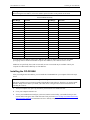
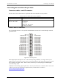
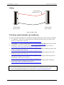
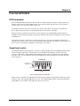
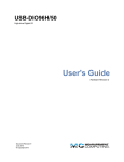
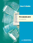
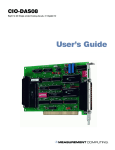
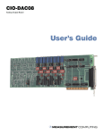
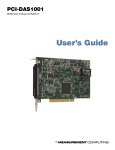
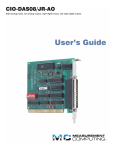
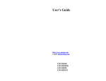
CIO-DIO48H Digital Input/Output Board User’s Guide Document Revision 1, December, 2006 © Copyright 2006, Measurement Computing Corporation Your new Measurement Computing product comes with a fantastic extra — Management committed to your satisfaction! Refer to www.mccdaq.com/execteam.html for the names, titles, and contact information of each key executive at Measurement Computing. Thank you for choosing a Measurement Computing product—and congratulations! You own the finest, and you can now enjoy the protection of the most comprehensive warranties and unmatched phone tech support. It’s the embodiment of our mission: To provide PC-based data acquisition hardware and software that will save time and save money. Simple installations minimize the time between setting up your system and actually making measurements. We offer quick and simple access to outstanding live FREE technical support to help integrate MCC products into a DAQ system. Lifetime warranty: Every hardware product manufactured by Measurement Computing Corporation is warranted against defects in materials or workmanship for the life of the product. Products found defective are repaired or replaced promptly. Lifetime Harsh Environment Warranty®: We will replace any product manufactured by Measurement Computing Corporation that is damaged (even due to misuse) for only 50% of the current list price. I/O boards face some tough operating conditions, some more severe than the boards are designed to withstand. When a board becomes damaged, just return the unit with an order for its replacement at only 50% of the current list price. We don’t need to profit from your misfortune. By the way, we honor this warranty for any manufacturer’s board that we have a replacement for. 30 Day Money Back Guarantee: You may return any Measurement Computing Corporation product within 30 days of purchase for a full refund of the price paid for the product being returned. If you are not satisfied, or chose the wrong product by mistake, you do not have to keep it. Please call for an RMA number first. No credits or returns accepted without a copy of the original invoice. Some software products are subject to a repackaging fee. These warranties are in lieu of all other warranties, expressed or implied, including any implied warranty of merchantability or fitness for a particular application. The remedies provided herein are the buyer’s sole and exclusive remedies. Neither Measurement Computing Corporation, nor its employees shall be liable for any direct or indirect, special, incidental or consequential damage arising from the use of its products, even if Measurement Computing Corporation has been notified in advance of the possibility of such damages. HM CIO-DIO48H.doc 3 Trademark and Copyright Information TracerDAQ, Universal Library, Harsh Environment Warranty, Measurement Computing Corporation, and the Measurement Computing logo are either trademarks or registered trademarks of Measurement Computing Corporation. Windows, Microsoft, and Visual Studio are either trademarks or registered trademarks of Microsoft Corporation LabVIEW is a trademark of National Instruments. CompactFlash is a registered trademark of SanDisk Corporation. XBee and XBee-PRO are trademarks of MaxStream, Inc. All other trademarks are the property of their respective owners. Information furnished by Measurement Computing Corporation is believed to be accurate and reliable. However, no responsibility is assumed by Measurement Computing Corporation neither for its use; nor for any infringements of patents or other rights of third parties, which may result from its use. No license is granted by implication or otherwise under any patent or copyrights of Measurement Computing Corporation. All rights reserved. No part of this publication may be reproduced, stored in a retrieval system, or transmitted, in any form by any means, electronic, mechanical, by photocopying, recording, or otherwise without the prior written permission of Measurement Computing Corporation. Notice Measurement Computing Corporation does not authorize any Measurement Computing Corporation product for use in life support systems and/or devices without prior written consent from Measurement Computing Corporation. Life support devices/systems are devices or systems which, a) are intended for surgical implantation into the body, or b) support or sustain life and whose failure to perform can be reasonably expected to result in injury. Measurement Computing Corporation products are not designed with the components required, and are not subject to the testing required to ensure a level of reliability suitable for the treatment and diagnosis of people. 4 Table of Contents Preface About this User's Guide .......................................................................................................................6 What you will learn from this user's guide .........................................................................................................6 Conventions in this user's guide .........................................................................................................................6 Where to find more information.........................................................................................................................6 Chapter 1 Introducing the CIO-DIO48H ................................................................................................................7 Overview: CIO-DIO48H features ......................................................................................................................7 Software features ................................................................................................................................................7 Chapter 2 Installing the CIO-DIO48H ....................................................................................................................8 What comes with your CIO-DIO48H shipment? ...............................................................................................8 Hardware .......................................................................................................................................................................... 8 Additional documentation................................................................................................................................................. 8 Optional components..........................................................................................................................................8 Unpacking the CIO-DIO48H .............................................................................................................................9 Installing the software ........................................................................................................................................9 Configuring the base address switch ..................................................................................................................9 Base address switch .......................................................................................................................................................... 9 Installing the CIO-DIO48H..............................................................................................................................10 Connecting the board for I/O operations ..........................................................................................................11 Connectors, cables – main I/O connector ........................................................................................................................11 Pinout – main I/O connector ............................................................................................................................................11 Cabling.............................................................................................................................................................................12 Field wiring, signal termination, and conditioning ..........................................................................................................12 Chapter 3 Functional Details ...............................................................................................................................13 82C55 emulation ..............................................................................................................................................13 Signal level control...........................................................................................................................................13 Digital I/O Isolation..........................................................................................................................................14 Chapter 4 Programming and Developing Applications ....................................................................................16 Programming languages ...................................................................................................................................16 Packaged applications programs ......................................................................................................................16 Register-level programming .............................................................................................................................16 Chapter 5 Specifications......................................................................................................................................17 Digital input/output ..........................................................................................................................................17 Power consumption ..........................................................................................................................................17 Environmental ..................................................................................................................................................17 Main connector and pin out..............................................................................................................................17 5 Preface About this User's Guide What you will learn from this user's guide This user's guide explains how to install, configure, and use the CIO-DIO48H board so that you get the most out of its analog output features. This user's guide also refers you to related documents available on our web site, and to technical support resources. Conventions in this user's guide The following conventions are used in this manual to convey special information: For more information on … Text presented in a box signifies additional information and helpful hints related to the subject matter you are reading. Caution! Shaded caution statements present information to help you avoid injuring yourself and others, damaging your hardware, or losing your data. <#:#> Angle brackets that enclose numbers separated by a colon signify a range of numbers, such as those assigned to registers, bit settings, etc. bold text Bold text is used for the names of objects on the screen, such as buttons, text boxes, and check boxes. For example: 1. Insert the disk or CD and click the OK button. italic text Italic text is used for the names of manuals and help topic titles, and to emphasize a word or phrase. For example: The InstaCal installation procedure is explained in the Quick Start Guide. Never touch the exposed pins or circuit connections on the board. Where to find more information The following electronic documents provide information relevant to the operation of the CIO-DIO48H. MCC's Specifications: CIO-DIO48H (the PDF version of the Specifications chapter in this guide) is available on our web site at www.mccdaq.com/pdfs/CIO-DIO48H.pdf. MCC's Quick Start Guide is available on our web site at www.mccdaq.com/PDFmanuals/DAQ-Software-Quick-Start.pdf. MCC's Guide to Signal Connections is available on our web site at www.mccdaq.com/signals/signals.pdf. MCC's Universal Library User's Guide is available on our web site at www.mccdaq.com/PDFmanuals/sm-ul-user-guide.pdf. MCC's Universal Library Function Reference is available on our web site at www.mccdaq.com/PDFmanuals/sm-ul-functions.pdf. MCC's Universal Library for LabVIEW™ User’s Guide is available on our web site at www.mccdaq.com/PDFmanuals/SM-UL-LabVIEW.pdf. CIO-DIO48H User's Guide (this document) is also available on our web site at www.mccdaq.com/PDFmanuals/CIO-DIO48H.pdf. 6 Chapter 1 Introducing the CIO-DIO48H Overview: CIO-DIO48H features The CIO-DIO48H provides 48-bits of digital I/O. The I/O is organized into two 24-bit groups based on an 82C55 mode 0 emulation. Each 24-bit group is divided into three eight-bit ports labeled An, Bn and Cn, where n is either "1" for FIRSTPORT or "2" for SECONDPORT. Port C can be split into two four-bit nibbles — Port C-HI and Port C-LO. Each of these ports may be individually programmed as input or output. All digital inputs are LSTTL. The output signals are buffered high output drive TTL. The digital output drivers are 74S244 chips that can sink 64 mA and source 15 mA. The input buffers are 74LS373 chips and have standard high input impedance of the 74LS series devices. On power up and reset, all I/O bits are set to input mode. If you are using the board to control items that must be OFF on reset, install pull-down resistors. The board is equipped with open locations where you can install SIP resistor networks for either pull-up or pull-down. All signals pass through a 50-pin connector. Software features For information on the features of InstaCal and the other software included with your CIO-DIO48H, refer to the Quick Start Guide that shipped with your device. The Quick Start Guide is also available in PDF at www.mccdaq.com/PDFmanuals/DAQ-Software-Quick-Start.pdf. Check www.mccdaq.com/download.htm for the latest software version. 7 Chapter 2 Installing the CIO-DIO48H What comes with your CIO-DIO48H shipment? The following items are shipped with the CIO-DIO48H. Hardware CIO-DIO48H Additional documentation In addition to this hardware user's guide, you should also receive the Quick Start Guide (available in PDF at www.mccdaq.com/PDFmanuals/DAQ-Software-Quick-Start.pdf). This booklet supplies a brief description of the software you received with your CIO-DIO48H and information regarding installation of that software. Please read this booklet completely before installing any software or hardware. Optional components C50FF-x cable Signal termination and conditioning accessories MCC provides signal conditioning and termination products for use with the CIO-DIO48H. Refer to Field wiring, signal termination, and conditioning on page 12 for a complete list of compatible accessory products. 8 CIO-DIO48H User's Guide Installing the CIO-DIO48H Unpacking the CIO-DIO48H As with any electronic device, you should take care while handling to avoid damage from static electricity. Before removing the CIO-DIO48H from its packaging, ground yourself using a wrist strap or by simply touching the computer chassis or other grounded object to eliminate any stored static charge. If any components are missing or damaged, notify Measurement Computing Corporation immediately by phone, fax, or e-mail: Phone: 508-946-5100 and follow the instructions for reaching Tech Support. Fax: 508-946-9500 to the attention of Tech Support Email: [email protected] Installing the software Refer to the Quick Start Guide for instructions on installing the software on the Measurement Computing Data Acquisition Software CD. This booklet is available in PDF at www.mccdaq.com/PDFmanuals/DAQ-SoftwareQuick-Start.pdf. Configuring the base address switch The CIO-DIO48H employs the PC bus for power, communications and data transfer. It draws power from the PC, monitors the address lines and control signals, responds to its I/O address, and receives and places data on the eight data lines. The CIO-DIO48H has one bank of base address-select switches. Verify their settings before installing the board in your computer. Base address switch The easiest way to set the base address is to let InstaCal show you the correct settings. However, if you are already familiar with setting ISA base addresses, you may use the base address switch description below to guide your base address selection. The base address is the starting location that software writes to when communicating with the CIO-DIO48H. A set of DIP switches is used to set the base address. By placing the switch down, the CIO-DIO48H address decode logic is instructed to respond to that address bit. A complete address is constructed by calculating the HEX or decimal number which corresponds to all the address bits the board has been instructed to respond to. The board is shipped with the base address set to 300 hex (see Figure 1). Unless there is already a board in your system that uses address 300 hex (768 decimal), leave the switches as they were set at the factory. 9 8 7 6 5 4 ADDRESS 3 SW A9 A8 A7 A6 A5 A4 A3 HEX 200 100 80 40 20 10 08 Figure 1. Base address switch In the default configuration, addresses 9 and 8 are down, and all others are up. Address 9 = 200 hex (512 decimal), and address 8 = 100 hex (256 decimal). When added together they equal 300 hex (768 decimal). 9 CIO-DIO48H User's Guide Installing the CIO-DIO48H Disregard the numbers printed on the switch When setting the base address, refer to the numbers printed in white on the printed circuit board. PC I/O Address Summary Hex Range Function Hex Range Function 000-00F 020-021 040-043 060-063 060-064 070-071 080-08F 0A0-0A1 0A0-0AF 0C0-0DF 0F0-0FF 1F0-1FF 200-20F 210-21F 238-23B 23C-23F 270-27F 2B0-2BF 8237 DMA #1 8259 PIC #1 8253 TIMER 8255 PPI (XT) 8742 CONTROLLER (AT) CMOS RAM & NMI MASK (AT) DMA PAGE REGISTERS 8259 PIC #2 (AT) NMI MASK (XT) 8237 #2 (AT) 80287 NUMERIC CO-P (AT) HARD DISK (AT) GAME CONTROL EXPANSION UNIT (XT) BUS MOUSE ALT BUS MOUSE PARALLEL PRINTER EGA 2C0-2CF 2D0-2DF 2E0-2E7 2E8-2EF 2F8-2FF 300-30F 310-31F 320-32F 378-37F 380-38F 3A0-3AF 3B0-3BB 3BC-3BF 3C0-3CF 3D0-3DF 3E8-3EF 3F0-3F7 3F8-3FF EGA EGA GPIB (AT) SERIAL PORT SERIAL PORT PROTOTYPE CARD PROTOTYPE CARD HARD DISK (XT) PARALLEL PRINTER SDLC SDLC MDA PARALLEL PRINTER EGA CGA SERIAL PORT FLOPPY DISK SERIAL PORT You can set the base address switch to any address in the range of 000-3F8. If you are not using IBM prototyping cards or another board which occupies these addresses, 300-31Fh are also free to use. Addresses not specifically listed, such as 390-39Fh, are not reserved and may be available. Check your computer for other boards which may use I/O addresses. Installing the CIO-DIO48H After you configure the base address, you can install the CIO-DIO48H into your computer. Follow the steps below. Install the MCC DAQ software before you install your board The driver needed to run your board is installed with the MCC DAQ software. Therefore, you need to install the MCC DAQ software before you install your board. Refer to the Quick Start Guide for instructions on installing the software. 1. Turn your computer off, open it up, and insert your board into an available ISA slot. 2. Close your computer and turn it on. 3. To test your installation and configure your board, run the InstaCal utility you installed in the previous section. Refer to the Quick Start Guide that came with your board www.mccdaq.com/PDFmanuals/DAQSoftware-Quick-Start.pdf for information on how to initially set up and load InstaCal. 10 CIO-DIO48H User's Guide Installing the CIO-DIO48H Connecting the board for I/O operations Connectors, cables – main I/O connector The table below lists the board connector, applicable cables, and compatible accessory products. Board connector, cables, and accessory equipment Connector type Compatible cables Compatible accessory products with the C50FF-x cable 50-pin shrouded male header C50FF-x CIO-TERM100 CIO-SPADE50 CIO-MINI50 SSR-RACK24, SSR-RACK48 CIO-ERB24, CIO-ERB48 Pinout – main I/O connector The CIO-DIO48H connector is a 50-pin male shrouded header connector that is accessible through the PC/AT expansion bracket. GND FIRSTPORTC Bit 0 FIRSTPORTC Bit 2 FIRSTPORTC Bit 4 FIRSTPORTC Bit 6 FIRSTPORTB Bit 0 FIRSTPORTB Bit 2 FIRSTPORTB Bit 4 FIRSTPORTB Bit 6 FIRSTPORTA Bit 0 FIRSTPORTA Bit 2 FIRSTPORTA Bit 4 FIRSTPORTA Bit 6 SECONDPORTC Bit 0 SECONDPORTC Bit 2 SECONDPORTC Bit 4 SECONDPORTC Bit 6 SECONDPORTB Bit 0 SECONDPORTB Bit 2 SECONDPORTB Bit 4 SECONDPORTB Bit 6 SECONDPORTA Bit 0 SECONDPORTA Bit 2 SECONDPORTA Bit 4 SECONDPORTA Bit 6 49 47 45 43 41 39 37 35 33 31 29 27 25 23 21 19 17 15 13 11 9 7 5 3 1 50 48 46 44 42 40 38 36 34 32 30 28 26 24 22 20 18 16 14 12 10 8 6 4 2 +5V FIRSTPORTC Bit 1 FIRSTPORTC Bit 3 FIRSTPORTC Bit 5 FIRSTPORTC Bit 7 FIRSTPORTB Bit 1 FIRSTPORTB Bit 3 FIRSTPORTB Bit 5 FIRSTPORTB Bit 7 FIRSTPORTA Bit 1 FIRSTPORTA Bit 3 FIRSTPORTA Bit 5 FIRSTPORTA Bit 7 SECONDPORTC Bit 1 SECONDPORTC Bit 3 SECONDPORTC Bit 5 SECONDPORTC Bit 7 SECONDPORTB Bit 1 SECONDPORTB Bit 3 SECONDPORTB Bit 5 SECONDPORTB Bit 7 SECONDPORTA Bit 1 SECONDPORTA Bit 3 SECONDPORTA Bit 5 SECONDPORTA Bit 7 Figure 2. I/O connector pin-out All the digital inputs and outputs are TTL. Under normal operating conditions, the voltages on the I/O pins range from near 0 volts for the low state, to near 5 volts for the high state. The voltages and currents of external devices usually exceed these values. Because of this, external relays are usually employed to handle higher current and voltage loads. In addition to load matching, digital signal sources often need to be filtered or "de-bounced". Refer to the Guide to Signal Connections for information on digital interfacing. This document is available at www.mccdaq.com/signals/signals.pdf 11 CIO-DIO48H User's Guide Installing the CIO-DIO48H Cabling 2 1 50 49 The red stripe identifies pin # 1 50-pin Female IDC Connector 2 1 50 49 50-pin Female IDC connector Figure 3. C50FF-x cable Field wiring, signal termination, and conditioning You can use the following cabling, screw termination, and signal conditioning products with the CIO-DIO48H. CIO-TERM100 – 100-pin screw terminal board (daisy-chained 50-pin IDC connectors). Details on this product are available on our web site at www.mccdaq.com/cbicatalog/cbiproduct.asp?dept_id=102&pf_id=281. CIO-SPADE50 – 16" X 4" termination panel which mates with both 37-pin and 50-pin connectors. Details on this product are available on our web site at www.mccdaq.com/pdfs/screw.pdf. CIO-MINI50 – 50-pin screw terminal board. Details on this product are available on our web site at www.mccdaq.com/cbicatalog/cbiproduct.asp?dept_id=102&pf_id=258. SSR-RACK24 – 24-channel, solid-state relay mounting rack for digital signal conditioning. Details on this product are available on our web site at www.mccdaq.com/cbicatalog/cbiproduct.asp?dept_id=122&pf_id=1193. SSR-RACK48 – 48-channel, solid-state relay mounting rack with quad-format modules. Details on this product are available on our web site at www.mccdaq.com/cbicatalog/cbiproduct.asp?dept_id=122&pf_id=622. CIO-ERB24 – 24 Form C relays, 6 Amp relay accessory board for digital signal conditioning. Details on this product are available on our web site at www.mccdaq.com/cbicatalog/cbiproduct.asp?dept_id=123&pf_id=241. CIO-ERB48 – 48 Form C relays, 6 Amp, relay, 50-pin accessory board for digital signal conditioning. Details on this product are available on our web site at www.mccdaq.com/cbicatalog/cbiproduct.asp?dept_id=123&pf_id=242. Information on signal connections General information regarding signal connection and configuration is available in the Guide to Signal Connections. This document is available on our web site at www.mccdaq.com/signals/signals.pdf. 12 Chapter 3 Functional Details 82C55 emulation The CIO-DIO48H emulates the 82C55 chip. The 82C55 emulation initializes all ports as inputs on power-up and reset. A TTL input is a high impedance input. If you connect another TTL input device to the output, it could be turned on or off every time the board is reset. To establish a consistent TTL level at power-up, use resistors tied to either +5V (pull-up) or ground (pulldown). There are open locations for pull-up and pull-down resistor packs on the board. Whenever an 82C55 emulation is powered on or reset, all pins are set to high-impedance input. Based on standard TTL functionality, these inputs will typically float high, and may have enough drive current to turn on external devices. Consequently, if you have output devices such as solid state relays, they may be switched on whenever the computer is powered on or reset. To prevent unwanted switching, and to drive all outputs to a known state after power on or reset, pull all pins either high or low through a 2.2 K resistor. Signal level control To safeguard against unwanted signal levels, the devices being controlled by the CIO-DIO48H board should be tied low or high as required by a 2.2K Ω resistor. In a 2.2K eight-resistor SIP pack, one side of all of the resistors is connected to a single common point and brought out to a pin. The common line, usually marked with a dot or line, is at one end of the SIP. The remaining resistor ends are brought out to the other eight pins (refer to Figure 4). 2.2KOhm SIP Dot indicates the common line (LO or HI) I/O Lines Figure 4. Eight-resistor SIP schematic Figure 5 shows a schematic of an SIP installed in both the pull-up and pull-down positions. Each port provides 10 holes in a line. The end labeled HI connects to +5V. The end marked LO connects to GND. The eight holes in the middle (n0 –n7) connect to the eight lines of the port (A, B or C). 13 CIO-DIO48H User's Guide Functional Details HI 2.2 K SIP COM n6 n6 n4 n3 n1 User Connector Digital I/O Lines n7 n2 n = A, B, or C HI n7 n5 Digital I/O Port +5 VDC Dot 2.2 K SIP User Connector Digital I/O Lines +5 VDC n5 Digital I/O Port n4 n3 n2 n = A, B, or C n0 n1 n0 LO (GND) LO (GND) 2.2 K SIP installed for pull-up COM Dot 2.2 K SIP installed for pull-down Figure 5. Pull-up and pull-down resistor SIPs schematic To pull-up lines, orient the SIP with the common pin (dot) toward the HI end; to pull-down, install the resistor with the common pin in the LO hole. When installing pull-up and pull-down resistor SIP packs, we recommend using 2.2K, eight-resistor Single Inline Packages (MCC part number SP-K2.29C). Use a different value only if necessary. Unconnected inputs float Unconnected inputs typically float high, but not reliably. If you are using a CIO-DIO48H for input and have unconnected inputs, ignore the data from those lines. You do not have to terminate input lines. Unconnected lines will not affect the performance of connected lines. Mask out any unconnected bits in software. Digital I/O Isolation To provide external signal conditioning and isolation, you can connect the CIO-DIO48H to a CIO-ERB24 or SSR-RACK24. The CIO-ERB24 provides 24 Form C electromechanical relays. The SSR-RACK24 is a mounting rack for 24 solid-state relays. The CIO-DIO48H provides digital I/O in groups of 48 bits. Many relay and solid-state relay (SSR) racks provide only 24-bits of digital I/O. You can configure the CIO-ERB24 relay output board and SSR-RACK24 I/O module rack in a daisy chain configuration to use all of the digital I/O bits provided by the CIO-DIO48H board. An example of the daisy chain configuration scheme for each board is shown on page 15. 14 CIO-DIO48H User's Guide Functional Details CIO-DIO48H IN CIO-ERB24 or SSR-RACK24 OUT IN CIO-ERB24 or SSR-RACK24 OUT Figure 6. CIO-DIO48H to CIO-ERB24 or SSR-RACK24 daisy chain The 24 digital I/O bits on pins 25 to 48 (base address +0 through +2) control the first relay board. The 24 digital I/O bits on pins 1 to 24 control the second relay/SSR board on the daisy chain. Use the C50FF-x cable for interconnections. You can also use SSR-RACK48 or the CIO-ERB48 series relay boards. 15 Chapter 4 Programming and Developing Applications After following the installation instructions in Chapter 2, your board should now be installed and ready for use. In general there may be no correspondence among registers for different boards. Software written at the register level for other models will not function correctly with your board. Programming languages Measurement Computing's Universal Library provides access to board functions from a variety of Windows programming languages. If you are planning to write programs, or would like to run the example programs for Visual Basic or any other language, refer to the Universal Library User's Guide (available on our web site at www.mccdaq.com/PDFmanuals/sm-ul-user-guide.pdf). Packaged applications programs Many packaged application programs now have drivers for your board. If the package you own does not have drivers for your board, please fax or e-mail the package name and the revision number from the install disks. We will research the package for you and advise how to obtain drivers. Some application drivers are included with the Universal Library package, but not with the application package. If you have purchased an application package directly from the software vendor, you may need to purchase our Universal Library and drivers. Please contact us by phone, fax or e-mail: Phone: 508-946-5100 and follow the instructions for reaching Tech Support. Fax: 508-946-9500 to the attention of Tech Support Email: [email protected] Register-level programming You should use the Universal Library or one of the packaged application programs mentioned above to control your board. Only experienced programmers should try register-level programming. If you need to program at the register level in your application, refer to the Register Map for the CIO-DIO48, CIO-DIO48H, CIO-DIO96, and CIO-DIO192. This document is available on our website at http://www.mccdaq.com/registermaps/RegMapCIO-DIO-Series.pdf. 16 Chapter 5 Specifications Typical for 25 °C unless otherwise specified. Specifications in italic text are guaranteed by design. Digital input/output Table 1. DIO specifications Digital type Configuration Number of channels Output high Output low Input high Input low Power-up / reset state Miscellaneous 8255 mode 0 emulation Output: 74S244 Input: 74LS373 4 banks of 8, 4 banks of 4, programmable by bank as input or output 48 I/O 2.4 volts min @ -15 mA 0.5 volts max @ 64 mA 2.0 volts min, 7 volts absolute max 0.8 volts max, -0.5 volts absolute min Input mode (high impedance) Locations provided for installation of pull-up or pull-down resistors. Power consumption Table 2. Power consumption specifications +5V 700 mA typical, 1200 mA max Environmental Table 3. Environmental specifications Operating temperature range Storage temperature range Humidity 0 to 50 °C -40 to +100 °C 0 to 90% non-condensing Main connector and pin out Table 4. Connector specifications Connector type Compatible cables Compatible accessory products with the C50FF-x 50-pin shrouded male header (P1) C50FF-x CIO-TERM100 CIO-SPADE50 CIO-MINI50 SSR-RACK24, SSR-RACK48 CIO-ERB24, CIO-ERB48 17 CIO-DIO48H User's Guide Specifications Table 5. Main connector pin out Pin 50 48 46 44 42 40 38 36 34 32 30 28 26 24 22 20 18 16 14 12 10 8 6 4 2 Signal name GND FIRSTPORTC Bit 0 FIRSTPORTC Bit 2 FIRSTPORTC Bit 4 FIRSTPORTC Bit 6 FIRSTPORTB Bit 0 FIRSTPORTB Bit 2 FIRSTPORTB Bit 4 FIRSTPORTB Bit 6 FIRSTPORTA Bit 0 FIRSTPORTA Bit 2 FIRSTPORTA Bit 4 FIRSTPORTA Bit 6 SECONDPORTC Bit 0 SECONDPORTC Bit 2 SECONDPORTC Bit 4 SECONDPORTC Bit 6 SECONDPORTB Bit 0 SECONDPORTB Bit 2 SECONDPORTB Bit 4 SECONDPORTB Bit 6 SECONDPORTA Bit 0 SECONDPORTA Bit 2 SECONDPORTA Bit 4 SECONDPORTA Bit 6 Pin 49 47 45 43 41 39 37 35 33 31 29 27 25 23 21 19 17 15 13 11 9 7 5 3 1 18 Signal name +5V FIRSTPORTC Bit 1 FIRSTPORTC Bit 3 FIRSTPORTC Bit 5 FIRSTPORTC Bit 7 FIRSTPORTB Bit 1 FIRSTPORTB Bit 3 FIRSTPORTB Bit 5 FIRSTPORTB Bit 7 FIRSTPORTA Bit 1 FIRSTPORTA Bit 3 FIRSTPORTA Bit 5 FIRSTPORTA Bit 7 SECONDPORTC Bit 1 SECONDPORTC Bit 3 SECONDPORTC Bit 5 SECONDPORTC Bit 7 SECONDPORTB Bit 1 SECONDPORTB Bit 3 SECONDPORTB Bit 5 SECONDPORTB Bit 7 SECONDPORTA Bit 1 SECONDPORTA Bit 3 SECONDPORTA Bit 5 SECONDPORTA Bit 7 Declaration of Conformity Manufacturer: Address: Category: Measurement Computing Corporation 10 Commerce Way Suite 1008 Norton, MA 02766 USA Electrical equipment for measurement, control and laboratory use. Measurement Computing Corporation declares under sole responsibility that the product CIO-DIO48H to which this declaration relates is in conformity with the relevant provisions of the following standards or other documents: EU EMC Directive 89/336/EEC: Electromagnetic Compatibility, EN55022 (1987), EN50082-1 Emissions: Group 1, Class B EN55022 (1987): Radiated and Conducted emissions. Immunity: EN50082-1 IEC 801-2 (1987): Electrostatic Discharge immunity, Criteria B. IEC 801-3 (1984): Radiated Electromagnetic Field immunity Criteria A. IEC 801-4 (1988): Electric Fast Transient Burst immunity Criteria B. Declaration of Conformity based on tests conducted by Chomerics Test Services, Woburn, MA 01801, USA in December, 1995. Test records are outlined in Chomerics Test Report #EMI0168B.95. We hereby declare that the equipment specified conforms to the above Directives and Standards. Carl Haapaoja, Director of Quality Assurance Measurement Computing Corporation 10 Commerce Way Suite 1008 Norton, Massachusetts 02766 (508) 946-5100 Fax: (508) 946-9500 E-mail: [email protected] www.mccdaq.com