1
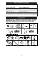
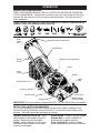
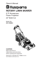
Owner’s Manual
ROTARY LAWN MOWER
6.75 Horsepower
Power-Propelled
22" Multi-Cut
Model No.
917.375810
CAUTION:
Read and follow all
Safety Rules and Instructions
before operating this equipment
Husqvarna, Charlotte, NC 28269 U.S.A.
Visit our website: www.husqvarna.com
TABLE OF CONTENTS
Warranty ...................................................2
Safety Rules ..........................................2-4
Product Specifications ..............................5
Assembly / Pre-Operation ........................6
Operation.............................................7-11
Maintenance Schedule ...........................11
Maintenance ......................................11-14
Service and Adjustments...................14-16
Storage ..............................................16-17
Troubleshooting .................................17-18
Repair Parts.......................................36-43
SAFETY RULES
IMPORTANT: This cutting machine is capable of amputating hands and feet and throwing objects. Failure to observe the following safety instructions could result in serious injury or death.
• Do not operate the mower when bareLook for this symbol to point out imfoot or wearing open sandals. Always
por tant safety precautions. It means
wear substantial foot wear.
CAUTION!!! BECOME ALERT!!!
•
Do
not pull mower backwards unless absoYOUR SAFETY IS INVOLVED.
lutely
necessary. Always look down and beWARNING: In order to prevent accidental
hind
before
and while moving backwards.
starting when setting up, transporting, ad•
Never
direct
discharged material toward
justing or making repairs, always disconnect
anyone.
Avoid
discharging material against
spark plug wire and place wire where it cannot
a
wall
or
obstruction.
Material may richocome in contact with plug.
chet
back
toward
the
operator. Stop the
WARNING: Engine exhaust, some of its
blade
when
crossing
gravel surfaces.
constituents, and certain vehicle compo•
Do
not
operate
the
mower
without
nents contain or emit chemicals known to
proper
guards,
plates,
grass
catcher or
the State of California to cause cancer and
oth
er
safety
protective
devices
in place.
birth defects or other reproductive harm.
•
See
manufacturer’s
instructions
for
WARNING: Battery posts, terminals and
proper
operation
and
installation
of
related accessories contain lead and lead
accessories.
Only
use
accessories
apcompounds, chemicals known to the State
proved
by
the
manufacturer.
of California to cause cancer and birth
• Stop the blade(s) when crossing gravel
defects or other reproductive harm. Wash
drives, walks, or roads.
hands after handling.
•
Stop the engine (motor) whenever you
CAUTION: Muffler and other engine
leave the equipment, before cleaning
parts become extremely
the mower or unclogging the chute.
hot during operation and
•
Shut the engine (motor) off and wait
remain hot after engine
until the blade comes to complete stop
has stopped. To avoid
before removing grass catcher.
severe burns on contact,
• Mow only in daylight or good artificial light.
stay away from these areas.
• Do not operate the machine while under
the influence of alcohol or drugs.
I. GENERAL OPERATION
•
Never operate machine in wet grass.
• Read, understand, and follow all
Always be sure of your footing: keep a
instructions on the machine and in the
firm hold on the handle; walk, never run.
manual(s) before starting. Be thoroughly
•
Disengage the self-propelled mechfamiliar with the controls and the proper
anism or drive clutch on mowers so
use of the machine before starting.
equipped before starting the engine.
• Do not put hands or feet near or under
•
If the equipment should start to vibrate
rotating parts. Keep clear of the disabnormally, stop the engine (motor) and
charge opening at all times.
check immediately for the cause. Vibra• Only allow responsible individuals, who
tion is generally a warning of trouble.
are familiar with the instructions, to
•
Always wear safety goggles or safety glassoperate the machine.
es with side shields when operating mower.
• Clear the area of objects such as rocks,
toys, wire, bones, sticks, etc., which
II. SLOPE OPERATION
could be picked up and thrown by blade. Slopes are a major factor related to slip &
• Be sure the area is clear of other people fall accidents which can result in severe
before mowing. Stop the machine if
injury. All slopes require extra caution. If
anyone enters the area.
2 you feel uneasy on a slope, do not mow it.
DO:
• Mow across the face of slopes: never
up and down. Exercise extreme caution
when changing direction on slopes.
• Remove obstacles such as rocks, tree
limbs, etc.
• Watch for holes, ruts, or bumps. Tall
grass can hide obstacles.
DO NOT:
• Do not trim near drop-offs, ditches or
embankments. The operator could lose
footing or balance.
• Do not trim excessively steep slopes.
• Do not mow on wet grass. Reduced
footing could cause slipping.
•
•
•
•
III. CHILDREN
Tragic accidents can occur if the operator is
not alert to the presence of children. Children
are often attracted to the machine and the
mowing activity. Never assume that children
will remain where you last saw them.
• Keep children out of the trimming area
and under the watchful care of another
responsible adult.
• Be alert and turn machine off if children
enter the area.
• Before and while walking backwards,
look behind and down for small children.
• Never allow children to operate machine.
• Use extra care when approaching blind
corners, shrubs, trees, or other objects
that may obscure vision.
a truck or trailer bed with a plastic liner.
Always place containers on the ground
away from your vehicle before filling.
Remove gas-powered equipment from
the truck or trailer and refuel it on the
ground. If this is not possible, then
refuel such equipment with a portable
container, rather than from a gasoline
dispenser nozzle.
Keep the nozzle in contact with the rim
of the fuel tank or container opening at
all times until fueling is complete. Do
not use a nozzle lock-open device.
If fuel is spilled on clothing, change
clothing immediately.
Never overfill fuel tank. Replace gas
cap and tighten securely.
V. GENERAL SERVICE
• Never run machine inside a closed area.
• Never make adjustments or repairs with
the engine (motor) running. Disconnect the
spark plug wire, and keep the wire away
from the plug to prevent accidental starting.
• Keep nuts and bolts, especially blade
attachment bolts, tight and keep equipment in good condition.
• Never tamper with safety devices. Check
their proper operation regularly.
• Keep machine free of grass, leaves, or
other debris build-up. Clean oil or fuel spillage. Allow machine to cool before storing.
• Stop and inspect the equipment if you
strike an object. Repair, if necessary,
before restarting.
• Never attempt to make wheel height
adjustments while the engine is running.
• Grass catcher components are subject to
wear, damage, and deterioration, which
could expose moving parts or allow objects
to be thrown. Frequently check components and replace with manufacturer’s
recommended parts, when necessary.
• Mower blades are sharp and can cut.
Wrap the blade(s) or wear gloves, and
use extra caution when ser vicing them.
• Do not change the engine governor setting or overspeed the engine.
• Maintain or replace safety and instruction labels, as necessary.
IV. SAFE HANDLING OF GASOLINE
Use extreme care in handling gasoline.
Gasoline is extremely flammable and the
vapors are explosive.
• Extinguish all cigarettes, cigars, pipes
and other sources of ignition.
• Use only an approved container.
• Never remove gas cap or add fuel with
the engine running. Allow engine to
cool before refueling.
• Never refuel the machine indoors.
• Never store the machine or fuel container where there is an open flame, spark
or pilot light such as a water heater or
on other appliances.
• Never fill containers inside a vehicle, on
WARNING: This lawn mower is equipped with an internal combustion engine and
should not be used on or near any unimproved forest-covered, brush-covered or
grass-covered land unless the engine’s exhaust system is equipped with a spark
arrester meeting applicable local or state laws (if any). If a spark arrester is used, it
should be maintained in effective working order by the operator.
In the state of California the above is required by law (Section 4442 of the California Public
Resources Code). Other states may have similar laws. Federal laws apply on federal
lands. A spark arrester for the muffler is available through your nearest Husqvarna or
other authorized service center (See the REPAIR PARTS section of this manual).
3
WARRANTY
SECTION 1: LIMITED WARRANTY
Husqvarna Forest & Garden Company (“Husqvarna”)
warrants Husqvarna product to the original purchaser
to be free from defects in material and workmanship
from the date of purchase for the “Warranty Period” of
the product as set forth below:
(4) Additional damage to parts or components due to
continued use occurring after any of the above.
REPAIR OR REPLACEMENT AS PROVIDED UNDER
THIS WARRANTY IS THE EXCLUSIVE REMEDY OF
THE PURCHASER. HUSQVARNA SHALL NOT BE
LIABLE FOR ANY INCIDENTAL OR CONSEQUENTIAL DAMAGES FOR BREACH OF ANY EXPRESS
OR IMPLIED WARRANTY ON THESE PRODUCTS
EXCEPT TO THE EXTENT PROHIBITED BY APPLICABLE LAW. ANY IMPLIED WARRANTY OF
MERCHANTABILITY OR FITNESS FOR A PARTICULAR PURPOSE ON THESE PRODUCTS IS LIMITED
IN DURATION TO THE WARRANTY PERIOD AS
DEFINED IN THE LIMITED WARRANTY STATEMENT.
HUSQVARNA RESERVES THE RIGHT TO CHANGE
OR IMPROVE THE DESIGN OF THE PRODUCT
WITHOUT NOTICE, AND DOES NOT ASSUME
OBLIGATION TO UPDATE PREVIOUSLY MANUFACTURED PRODUCTS.
2 YEAR NON-COMMERCIAL WARRANTY: Automatic
Mower, Riding lawn mowers, yard and garden tractors,
walk behind mowers, tillers, chain saws, trimmers,
brushcutters, clearing saws, snow blowers, handheld
blowers, backpack blowers, hedge trimmers, electrical products and power-assist collection systems for
noncommercial, nonprofessional, noninstitutional or
nonincome producing use, except as herein stated.
Emission control system components necessary to
comply with CARB-TIER-II and EPA regulations.
Husqvarna Safety Apparel carries a 90-day warranty
from the date of the customer’s original purchase for
defects in material and workmanship. Normal wear,
tear or abuse is not covered under warranty. Product
must be returned to Charlotte with a warranty claim
form. All care and maintenance instructions must be
followed as stated by the manufacturer on the care label. The fit of the protective apparel/boot is not covered
under warranty.
Some states do not allow the exclusion of incidental
or consequential damages, or limitations on how long
an implied warranty lasts, so the above limitations or
exclusions may not apply to you. This warranty gives
you specific legal rights, and you may also have other
rights which vary from state to state.
SECTION 5: CUSTOMER RESPONSIBILITIES
The product must exhibit reasonable care, maintenance, operation, storage and general upkeep as
written in the maintenance section of the Owner’s/
Operator’s manual. Should an operational problem
or failure occur, the product should not be used, but
delivered as is to an authorized Husqvarna dealer for
evaluation. Proof of purchase, as explained in section
6, rests solely with the customer.
SECTION 2: HUSQVARNA’S OBLIGATIONS UNDER
THE WARRANTY
Husqvarna will repair or replace defective components
without charge for parts or labor if a component fails
because of a defect in material or workmanship during
the warranty period.
SECTION 3: ITEMS NOT COVERED BY THIS WARRANTY
The following items are not covered by this warranty:
(1)Normal customer maintenance items which become
worn through normal regular use, including, but
not limited to, belts, blades, blade adapters, bulbs,
filters, guide bars, lubricants, rewind springs, saw
chain, spark plugs, starter ropes and tines;
(2) Natural discoloration of material due to ultraviolet
light;
(3) Lawn and garden attachments are covered by a
third party which gives a warranty, all claims for
warranty should be sent to the manufacturer; and
(4)Emission Control System components necessary
to which are manufactured by third party engine
manufacturer.
SECTION 6: PROCEDURE TO OBTAIN WARRANTY
CONSIDERATION
It is the Owner’s and Dealer’s responsibility to make
certain that the Warranty Registration Card is properly
filled out and mailed to Husqvarna Forest & Garden
Company. This card should be mailed within ten (10)
days from the date of purchase in order to confirm the
warranty and to facilitate post-sale service.
Proof of purchase must be presented to the authorized
Husqvarna dealer in order to obtain warranty service.
This proof must include date purchased, model number, serial number, and complete name and address of
the selling dealer.
SECTION 4: EXCEPTIONS AND LIMITATIONS
This warranty shall be inapplicable to defects resulting
from the following:
(1) Accident, abuse, misuse, negligence and neglect,
including stale fuel, dirt, abrasives, moisture, rust,
corrosion, or any adverse reaction due to incorrect
storage or use habits;
(2) Failure to operate or maintain the unit in accordance with the Owner’s/Operator’s manual or
instruction sheet furnished by Husqvarna;
(3) Alterations or modifications that change the
intended use of the product or affects the product’s
performance, operation, safety, or durability, or
causes the product to fail to comply with any applicable laws; or:
To obtain the benefit of this warranty, the product
believed to be defective must be delivered to an
authorized Husqvarna dealer in a timely manner, no
later than thirty (30) days from date of the operational
problem or failure. The product must be delivered at
the owner’s expense. Pick-up and delivery charges are
not covered by this warranty. An authorized Husqvarna
dealer can be normally located through the “Yellow
Pages” of the local telephone directory or by calling
1-800-HUSKY62 for a dealer in your area.
HUSQVARNA
7349 Statesville Road
Charlotte, NC 28269
531 83 81-23 2002
4
PRODUCT SPECIFICATIONS
Serial Number:
Date of Purchase:
Gasoline Capacity / Type:
1.6 Quarts (Unleaded Regular)
Oil Type (API SG–SL):
SAE 30 (above 32°F); SAE 5W-30 (below 32°F)
Oil Capacity:
20 Ounces
Spark Plug (Gap: .030")
Champion J19LM or RJ19LM
Blade Bolt Torque:
35-40 ft. lbs.
• The model and serial numbers will be found on a decal on the rear of the lawn mower
housing. Record both serial number and date of purchase in space provided above.
ACCESSORIES
These accessories were available when this lawn mower was produced. They are not
shipped with your mower. They are also available at most Husqvarna retailers and
service centers. Some of these accessories may not apply to your lawn mower.
5
ASSEMBLY / PRE-OPERATION
Read these instructions and this manual in its entirety before you attempt to assemble or
operate your new lawn mower.
IMPORTANT: This lawn mower is shipped WITHOUT OIL OR GASOLINE in the engine.
Your new lawn mower has been assembled at the factory with the exception of those parts
left unassembled for shipping pur poses. To ensure safe and proper operation of your lawn
mower, all parts and hardware you assemble must be tightened securely. Use the correct
tools as necessary to ensure proper tightness. All parts such as nuts, washers, bolts, etc.,
necessary to complete the assembly have been placed in the parts bag.
TO ASSEMBLE GRASS CATCHER
1. Put grass catcher frame into grass bag
with rigid part of bag on the bottom.
Make sure the frame handle is outside
of the bag top.
2. Slip vinyl bindings over frame.
NOTE: If vinyl bindings are too stiff, hold
them in warm water for a few minutes. If
bag gets wet, let it dry before using.
TO REMOVE MOWER FROM CARTON
1. Remove loose parts included with mower.
2. Cut down two end corners of carton
and lay end panel down flat.
3. Remove all packing materials except
padding between upper and lower
handle and padding holding operator
presence control bar to upper handle.
4. Roll lawn mower out of carton and
check carton thoroughly for additional
loose parts.
Frame
handle
HOW TO SET UP YOUR MOWER
TO UNFOLD HANDLE
IMPORTANT: Unfold handle carefully so
as not to pinch or damage control cables.
1. Raise handles until lower handle section locks into place in mowing position.
2. Remove protective padding, raise upper handle section into place on lower
handle and tighten both handle knobs.
3. Remove handle padding holding operator
presence control bar to upper handle.
Your lawn mower handle can be adjusted
for your mowing comfort. Refer to “ADJUST HANDLE” in the Service and Adjustments section of this manual.
Operator
presence
control bar
Vinyl
bindings
TO INSTALL ATTACHMENTS
Your lawn mower was shipped ready to be
used as a mulcher. To convert mower to
bagging or discharging, see “TO CONVERT MOWER” in the Operation section
of this manual.
MOWING
POSITION
LIFT
UP
LIFT
UP
Frame
opening
Upper
handle
Handle
knob
Lower handle
6
OPERATION
KNOW YOUR LAWN MOWER
READ THIS OWNER'S MANUAL AND ALL SAFETY RULES BEFORE OPERATING
YOUR LAWN MOWER. Compare the illustrations with your lawn mower to familiarize
yourself with the location of various controls and adjustments. Save this manual for
future reference.
These symbols may appear on your lawn mower or in literature supplied with the
product. Learn and understand their meaning.
Drive
control
lever
Operator presence control bar
Handle knob
Engine oil cap with dipstick
Starter
handle
Primer
Grass
catcher
Muffler
Spark
plug
Gasoline filler cap
Air filter
Drive cover
Mulcher door
Wheel adjuster
(on each wheel)
Housing
IMPORTANT: This lawn mower is shipped WITHOUT OIL OR GASOLINE in the engine.
MEETS CPSC SAFETY REQUIREMENTS
Our rotary walk-behind power lawn mowers conform to the safety standards of the
American National Standards Institute and the U.S. Consumer Product Safety Commission. The blade turns when the engine is running.
Operator presence control bar – must
be held down to the handle to start the
engine. Release to stop the engine.
Primer– pumps additional fuel from the
carburetor to the cylinder for use when
starting a cold engine.
Starter handle – used for starting engine.
Mulcher door – allows conversion to
discharging or bagging operation.
Drive control lever – used to engage
power-propelled forward motion of mower.
7
The operation of any lawn
mower can result in foreign
objects thrown into the eyes,
which can result in severe
eye damage. Always wear
safety glasses or eye shields while operating your lawn mower or performing any
adjustments or repairs. We recommend a
standard safety glasses or wide vision safety
mask worn over spectacles.
HOW TO USE YOUR LAWN MOWER
ENGINE SPEED
The engine speed was set at the factory
for optimum performance. Speed is not
adjustable.
ENGINE ZONE CONTROL
CAUTION: Federal regulations require
an engine control to be installed on this
lawn mower in order to minimize the
risk of blade contact injury. Do not under
any circumstances attempt to defeat the
function of the operator control. The blade
turns when the engine is running.
• Your lawn mower is equipped with an
operator presence control bar which
requires the operator to be positioned
behind the lawn mower handle to start
and operate the lawn mower.
DRIVE CONTROL
• Self-propelling is controlled by holding the operator presence control bar
down to the handle and pulling the drive
control lever rearward to the handle.
The farther toward the handle the lever
is pulled, the faster the unit will travel.
• Forward motion will stop when either
the operator presence control bar or
drive control lever are released. To stop
forward motion without stopping engine,
release the drive control lever only. Hold
operator presence control bar down
against handle to continue mowing
without self-propelling.
NOTE: If after releasing the drive control
the mower will not roll backwards, push
the mower forward slightly to disengage
drive wheels.
• To keep drive control engaged when
turning corners, push down on the
handle to lift the front wheels off the
ground while turning lawn mower.
DRIVE CONTROL ADJUSTMENT
Over time, the drive control system may
become “loose”, resulting in decreased
speed. There is a turnbuckle on the
underside of the drive control housing to
increase tension on the drive cable. Proceed as follows:
8
1. Turn unit off and disconnect spark plug
wire from spark plug.
2. Turn nut on underside of drive control
to increase drive speed.
3. Operate mower to test drive speed.
Readjust as required.
4. If condition fails to improve after the
above steps (forward speed remains
the same), your drive belt is worn and
should be replaced.
Operator presence control bar
TO
ENGAGE
Adjustment DRIVE
turnbuckle CONTROL
Drive
control
lever
DRIVE
CONTROL
DISENGAGED
TO ADJUST CUTTING HEIGHT
Raise wheels for low cut and lower wheels
for high cut, adjust cutting height to suit
your requirements. Medium position is
best for most lawns.
• To change cutting height, squeeze adjuster lever toward wheel. Move wheel
up or down to suit your requirements. Be
sure all wheels are in the same setting.
NOTE: Adjuster is properly positioned
when plate tab inserts into hole in lever.
Also, 9-position adjusters (if so equipped)
allow lever to be positioned between the
plate tabs.
LEVER BACKWARD
TO LOWER MOWER
Plate tab
LEVER FORWARD TO RAISE MOWER
Lever
TO CONVERT MOWER
Your lawn mower was shipped ready to be
used as a mulcher. To convert to bagging
or discharging:
REAR BAGGING
• Open rear door, remove mulcher plug.
Store mulcher plug in a safe place.
• You can now install the grass catcher or
optional clipping deflector.
• To convert to mulching or discharging
operation, install mulcher plug into rear
discharge opening of mower.
Discharge deflector
Mulcher plug
SIDE DISCHARGING
• Mulcher plug must be installed into rear
discharge opening of mower.
• Open mulcher door and install discharge deflector under door as shown.
• Mower is now ready for discharging
operation.
• To convert to mulching or bagging
operation, discharge deflector must be
removed and mulcher door closed.
SIMPLE STEPS TO REMEMBER WHEN
CONVERTING YOUR LAWN MOWER
FOR MULCHING 1. Rear mulcher plug installed.
2. Mulcher door closed.
FOR REAR BAGGING 1. Rear mulcher plug removed.
2. Grass catcher installed.
3. Mulcher door closed.
TO EMPTY
GRASS CATCHER
1. Lift up on grass catcher using the
frame handle.
2. Remove grass catcher with clippings
from under lawn mower handle.
3. Empty clippings from bag.
NOTE: Do not drag the bag when emptying; it will cause unnecessary wear.
Grass
catcher
frame
handle
FOR SIDE DISCHARGING 1. Rear mulcher plug installed.
2. Discharge deflector installed.
CAUTION: Do not run your lawn
mower without mulcher plug or approved
grass catcher in place. Never attempt to
operate the lawn mower with the rear door
removed or propped open.
BEFORE STARTING ENGINE
Open mulcher door
ADD OIL
Your lawnmower is shipped without oil in
the engine. For type and grade of oil to
use, see “ENGINE” in the Maintenance
section of this manual.
CAUTION: DO NOT overfill engine with
oil, or it will smoke heavily from the muffler
on startup.
1. Be sure lawnmower is level.
2. Remove oil dipstick from oil fill spout.
3. You receive a container of oil with the
unit. Slowly pour the entire container
down the oil fill spout into the engine.
9
NOTE: Initial oil fill requires only 18 oz.
due to residual oil in engine from the
manufacturers 100% quality testing. When
changing oil you may need 20 oz.
4. Insert and tighten dipstick.
IMPORTANT:
• Check oil level before each use. Add oil
if needed. Fill to full line on dipstick.
• Change the oil after every 25 hours of
operation or each season. You may
need to change the oil more often
under dusty, dirty conditions. See “TO
CHANGE ENGINE OIL” in the Maintenance section of this manual.
TO STOP ENGINE
• To stop engine, release operator presence control bar.
TO START ENGINE
Gasoline
filler cap
NOTE: Due to protective coatings on the
engine, a small amount of smoke may be
present during the initial use of the product and should be considered normal.
1. To start a cold engine, push primer
three (3) times before trying to start.
Use a firm push. This step is not
usually necessary when starting an
engine which has already run for a few
minutes.
2. Hold operator presence control bar
down to the handle and pull starter
handle quickly. Do not allow starter
rope to snap back.
NOTE: In cooler weather it may be
necessary to repeat priming steps. In
warmer weather over priming may cause
flooding and engine will not start. If you do
flood engine, wait a few minutes before
attempting to start and do not repeat
priming steps.
Primer
MOWING TIPS
ADD GASOLINE
• Fill fuel tank to bottom of tank filler neck.
Do not overfill. Use fresh, clean, regular
unleaded gasoline with a minimum of
87 octane. Do not mix oil with gasoline.
Purchase fuel in quantities that can be
used within 30 days to assure fuel freshness.
CAUTION: Wipe off any spilled oil or
fuel. Do not store, spill or use gasoline
near an open flame.
CAUTION: Alcohol blended fuels
(called gasohol or using ethanol or methanol) can attract moisture which leads to
separation and formation of acids during
storage. Acidic gas can damage the fuel
system of an engine while in storage. To
avoid engine problems, the fuel system
should be emptied before storage of 30
days or longer. Empty the gas tank, start
the engine and let it run until the fuel lines
and carburetor are empty. Use fresh fuel
next season. See Storage Instructions for
additional information. Never use engine
or carburetor cleaner products in the fuel
tank or permanent damage may occur.
CAUTION: Do not use de-thatcher
blade attachments on your mower. Such
attachments are hazardous, will damage
your mower and could void your warranty.
• Under certain conditions, such as very
tall grass, it may be necessary to raise
the height of cut to reduce pushing
effort and to keep from overloading the
engine and leaving clumps of grass clippings. It may also be necessary to reduce ground speed and/or run the lawn
mower over the area a second time.
• For extremely heavy cutting, reduce the
width of cut by overlapping previously
cut path and mow slowly.
• For better grass bagging and most cutting conditions, the engine speed should
be set in the FAST position.
• Pores in cloth grass catchers can become filled with dirt and dust with use
and catchers will collect less grass. To
prevent this, regularly hose catcher off
with water and let dry before using.
• Keep top of engine around starter clear
and clean of grass clippings and chaff.
This will help engine air flow and extend
engine life.
Engine
oil cap
10
cut to reduce pushing effort and to keep
from overloading the engine and leaving
clumps of mulched grass. For extremely
heavy grass, reduce your width of cut
by overlapping previously cut path and
mow slowly.
• Certain types of grass and grass
conditions may require that an area be
mulched a second time to completely
hide the clippings. When doing a second cut, mow across (perpendicular) to
the first cut path.
MULCHING MOWING TIPS
IMPORTANT: For best performance,
keep mower housing free of built-up
grass and trash. See “CLEANING” in the
Maintenance section of this manual.
• The special mulching blade will recut
the grass clippings many times and
reduce them in size so that as they fall
onto the lawn they will disperse into
the grass and not be noticed. Also, the
mulched grass will biodegrade quickly
to provide nutrients for the lawn. Always
mulch with your highest engine (blade)
speed as this will provide the best recutting action of the blades.
• Avoid cutting your lawn when it is wet.
Wet grass tends to form clumps and
interferes with the mulching action. The
best time to mow your lawn is the early
afternoon. At this time the grass has
dried, yet the newly cut area will not be
exposed to direct sunlight.
• For best results, adjust the lawn mower
cutting height so that the lawn mower
cuts off only the top one-third of the
grass blades. If the lawn is overgrown it
will be necessary to raise the height of
MAX 1/3
• Change your cutting pattern from week
to week. Mow north to south one week
then change to east to west the next
week. This will help prevent matting and
graining of the lawn.
MAINTENANCE
BEFORE
EACH
USE
AFTER
EACH
USE
EVERY
10
HOURS
EVERY
25 HOURS
OR SEASON
EVERY
100
HOURS
BEFORE
STORAGE
Check for Loose Fasteners
Clean / Inspect Grass Catcher *
Check Tires
Check Drive Wheels ***
Clean Lawn Mower ****
Clean under Drive Cover ***
Check Drive Belt / Pulleys ***
Check / Sharpen / Replace Blade
Lubrication
Clean and Recharge Battery **
Check Engine Oil level
Change Engine Oil
Clean Air Filter
Inspect Muffler
Replace Spark Plug
Replace Air Filter Paper Cartridge
Empty fuel system or add Stabilizer
* (if so equipped)
** Electric-Start mowers
*** Power-Propelled mowers
a scraper
**** Use
to clean under deck
1 - Change more often if operating under a heavy load or in high outdoor temperatures.
2 - Service more often if operating in dirty or dusty conditions.
3 - Replace blades more often when mowing in sandy soil.
4 - Charge 48 hours at end of season.
5 - And after each 5 hours of use.
11
GENERAL RECOMMENDATIONS
LAWN MOWER
The warranty on this lawn mower does not
cover items that have been subjected to
operator abuse or negligence. To receive
full value from the warranty, operator must
maintain unit as instructed in this manual.
Some adjustments will need to be made
periodically to properly maintain your unit.
At least once a season, check to see if
you should make any of the adjustments
described in the Service and Adjustments
section of this manual.
• At least once a year, replace the spark
plug, clean or replace air filter element
and check blade for wear. A new spark
plug and clean/new air filter element
assure proper air-fuel mixture and help
your engine run better and last longer.
• Follow the maintenance schedule in this
manual.
Always observe safety rules when performing any maintenance.
TIRES
• Keep tires free of gasoline, oil, or insect
control chemicals which can harm rubber.
• Avoid stumps, stones, deep ruts, sharp
objects and other hazards that may
cause tire damage.
DRIVE WHEELS
Check front drive wheels each time before
you mow to be sure they move freely.
The wheels not turning freely means trash,
grass cuttings, etc. are in the drive wheel area
and must be cleaned to free drive wheels.
If necessary to clean the drive wheels, be
sure to clean both front wheels.
1. Remove hubcaps, locknuts & washers.
2. Remove wheels from wheel adjusters.
3. Remove any trash or grass cuttings
from inside the dust cover, pinion and/
or drive wheel gear teeth.
4. Put wheels back in place.
NOTE: If after cleaning, the drive wheels
do not turn freely, contact a Husqvarna or
other qualified service center.
BLADE CARE
For best results, blade must be kept sharp.
Replace a bent or damaged blade.
CAUTION: Use only a replacement blade
approved by the manufacturer of your mower.
Using a blade not approved by the manufacturer of your mower is hazardous, could
damage your mower and void your warranty.
BEFORE EACH USE
• Check engine oil level.
• Check for loose fasteners.
LUBRICATION
Keep unit well lubricated
(See “LUBRICATION CHART”).
LUBRICATION CHART
➀ Wheel
adjuster (on
each wheel)
➁ Engine oil
➀ Mulcher
door hinge
pin
➀ Rear door
hinge
➀ Handle bracket mounting pins
➀ Spray lubricant
➁ See "ENGINE" in Maintenance section.
IMPORTANT: Do not oil or grease plastic
wheel bearings. Viscous lubricants will
attract dust and dirt that will shorten the life of
the self-lubricating bearings. If you feel they
must be lubricated, use only a dry, powdered
graphite type lubricant sparingly.
12
TO REMOVE BLADE
1. Disconnect spark plug wire from spark
plug and place wire where it cannot
come in contact with plug.
2. Turn lawn mower on its side. Make
sure air filter and carburetor are up.
3. Use a wood block between blade and
mower housing to prevent blade from
turning when removing blade bolt.
NOTE: Protect your hands with gloves
and/or wrap blade with heavy cloth.
4. Remove blade bolt by turning counterclockwise.
5. Remove blade & attaching hardware
(bolt, lock washer & hardened washer).
TO REPLACE BLADE
1. Position blade on the blade adapter
aligning the two (2) holes in the blade
with the raised lugs on the adapter.
2. Be sure the trailing edge of blade (opposite sharp edge) is up toward the engine.
3. Install the blade bolt with the lock
washer and hardened washer into
blade adapter and crankshaft.
4. Use block of wood between blade and
lawn mower housing and tighten the
blade bolt, turning clockwise.
• The recommended tightening torque is
35-40 ft. lbs.
IMPORTANT: Blade bolt is heat treated.
If bolt needs replacing, replace only with
approved bolt shown in the Repair Parts
section of this manual.
Blade adapter
Key
Crankshaft
keyway
LUBRICATION
Use only high quality detergent oil rated with
API service classification SG–SL. Select the
oil's SAE viscosity grade according to your
expected operating temperature.
SAE VISCOSITY GRADES
SAE 30
5W-30
-20
F
C
Lockwasher
-30
0
-20
30
-10
32
0
40
60
10
100
80
20
30
40
TEMPERATURE RANGE ANTICIPATED BEFORE NEXT OIL CHANGE
Blade
Blade
bolt Hardened
washer
ENGINE
Trailing edge
Crankshaft
NOTE: Although multi-viscosity oils
(5W30, 10W30 etc.) improve starting in
cold weather, these multi-viscosity oils will
result in increased oil consumption when
used above 32°F. Check your engine oil
level more frequently to avoid possible
engine damage from running low on oil.
Change the oil after every 25 hours of operation orat least once a year if the mower
is not used for 25 hours in one year.
Check the crankcase oil level before
starting the engine and after each five (5)
hours of continuous use. Tighten oil plug
securely each time you check the oil level.
TO SHARPEN BLADE
NOTE: We do not recommend sharpening
the blade - but if you do, be sure the blade
is balanced. Care should be taken to keep
the blade balanced. An unbalanced blade will
cause eventual damage to mower or engine.
• The blade can be sharpened with a file
TO CHANGE ENGINE OIL
or on a grinding wheel. Do not attempt
NOTE: Before tipping lawn mower to drain
to sharpen while on the mower.
• To check blade balance, drive a nail into oil, empty fuel tank by running engine until
fuel tank is empty.
a beam or wall. Leave about one inch of
1. Disconnect spark plug wire from spark
the straight nail exposed. Place center
plug and place wire where it cannot
hole of blade over the head of the nail.
come in contact with plug.
If blade is balanced, it should remain in
2. Remove engine oil cap; lay aside on a
a horizontal position. If either end of the
clean surface.
blade moves downward, sharpen the
3. Tip lawn mower on its side as shown
heavy end until the blade is balanced.
and drain oil into a suitable container.
GRASS CATCHER
Rock lawn mower back and forth to re• The grass catcher may be hosed with
move any oil trapped inside of engine.
water, but must be dry when used.
• Check your grass catcher often for damage or deterioration. Through normal
use it will wear. If catcher needs replacing, replace only with approved replacement catcher shown in the Repair Parts
section of this manual. Give the lawn
mower model number when ordering.
GEAR CASE
• To keep your drive system working
properly, the gear case and area around
Container
the drive should be kept clean and free
4. Wipe off any spilled oil from lawn
of trash build-up. Clean under the drive
mower or side of engine.
cover twice a season.
• The gear case is filled with lubricant to the 5. Slowly pour oil down the oil fill spout,
stopping every few ounces to check the
proper level at the factory. The only time
oil level with the dipstick.
the lubricant needs attention is if service
6. Stop adding oil when you reach the
has been performed on the gear case.
FULL mark on the dipstick. Wait a
• If lubricant is required, use only Elf Mul13 minute to allow oil to settle.
tis EP00. Do not substitute.
7. Continue adding small amounts of oil,
rechecking the dipstick until oil level
settles at FULL. DO NOT overfill, or
engine will smoke heavily from the muffler on startup.
8. Always be sure to retighten oil dipstick
before starting engine.
9. Reconnect spark plug wire to spark plug.
AIR FILTER
Your engine will not run properly and may
be damaged by using a dirty air filter.
Replace the air filter cartridge every 100
hours of operation or every season, whichever occurs first. Service air cleaner more
often under dusty conditions.
Lip
CLEANING
IMPORTANT: For best performance,
keep mower housing free of built-grass
and trash. Clean the underside of your
mower after each use.
CAUTION: Disconnect spark plug wire
from spark plug and place wire where it
cannot come in contact with plug.
• Clean the underside of your lawn
mower by scraping to remove build-up
of grass and trash.
• Clean engine often to keep trash from
accumulating. A clogged engine runs
hotter and shortens engine life.
• Keep finished surfaces and wheels free
of all gasoline, oil, etc.
• We do not recommend using a garden
hose to clean lawn mower unless the
electrical system, muffler, air filter and
carburetor are covered to keep water
out. Water in engine can result in shortened engine life.
CLEAN UNDER DRIVE COVER
Clean under drive cover at least twice a season. Scrape underside of cover with putty
knife or similar tool to remove any build-up
of trash or grass on underside of drive cover.
Back plate
Cartridge
Slot
Cover
4. Install cartridge, then replace cover.
Be sure tabs are aligned with slots in
the back plate. Fasten screw securely.
MUFFLER
Inspect and replace corroded muffler as it
could create a fire hazard and/or damage.
SPARK PLUG
Replace spark plug at the beginning of
each mowing season or after every 100
hours of operation, whichever occurs
first. Spark plug type and gap setting
are shown in the “PRODUCT SPECIFICATIONS” section of this manual.
Cover
tab
TO CLEAN AIR FILTER
1. Loosen screw and tilt cover to remove.
2. Carefully remove cartridge.
3. Clean by gently tapping on a flat surface. If very dirty, replace car tridge.
CAUTION: Petroleum solvents, such as
kerosene, are not to be used to clean cartridge. They may cause deterioration of the
cartridge. Do not oil car tridge. Do not use
pressurized air to clean or dry car tridge.
SERVICE AND ADJUSTMENTS
WARNING: To avoid serious injury, before performing any service and adjustments:
1. Release control bar and stop engine.
2. Make sure the blade and all moving parts have completely stopped.
3. Disconnect spark plug wire from spark plug and place wire where it cannot come in
contact with plug.
REAR DEFLECTOR
LAWN MOWER
The rear deflector, attached between the
TO ADJUST CUTTING HEIGHT
rear wheels of your mower, is provided to
See “TO ADJUST CUTTING HEIGHT” in
minimize the possibility that objects will
the Operation section of this manual.
be thrown out of the rear of the mower
into the operator mowing position. If the
deflector becomes damaged, it should be
replaced.
14
TO REMOVE DRIVE BELT
1. Remove drive cover and belt keeper.
2. Remove belt from gearcase pulley by
pushing down on pulley and rolling belt
off it.
3. Turn lawn mower on its side with air
filter and carburetor down.
4. Remove blade and debris shield.
5. Remove belt from engine pulley on
crankshaft.
TO REPLACE DRIVE BELT
1. Place new drive belt in the belt retainers of the debris shield.
2. Route the other end of the new drive
belt through hole in housing.
3. Reinstall debris shield and blade.
4. Return mower to upright position.
5. Install new belt on gearcase pulley.
6. Reinstall belt keeper and drive cover.
NOTE: Always use factory approved belt
to assure proper fit and long life.
TO ADJUST HANDLE
The handle can be mounted in a high or
low position. The mounting holes in the
bottom of lower handle are off center for
raising or lowering the handle.
1. Remove upper handle and wire tie(s)
securing cable(s) to lower handle.
2. Remove hairpin cotters from lower
handle bracket mounting pin.
3. Squeeze lower handle in to remove it
from mounting pins.
4. Turn lower handle over to raise or
lower handle.
5. Squeeze lower handle in and position holes
onto mounting pins on handle bracket.
6. Reassemble upper handle and all
parts removed from lower handle.
SQUEEZE
TO ADJUST
Lower handle
Drive
cover
Belt
keeper
Mounting pin
Handle
bracket
Hairpin cotter
Mowing
position
PUSH
DOWN
Mowing
position
Hairpin
Handle
cotter
bracket
Mounting
pin
LOW POSITION
HIGH POSITION
Belt
Belt retainers
Drive belt
Lower
handle
Debris shield
ROTATE
15
ENGINE
your lawn mower to a Husqvarna or other
qualified service center for repair and/or
adjustment.
IMPORTANT: Never tamper with the
engine governor, which is factory set for
proper engine speed. Overspeeding
the engine above the factory high speed
setting can be dangerous. If you think
the engine-governed high speed needs
adjusting, contact a Husqvarna or other
qualified service center, which has proper
equipment and experience to make any
necessary adjustments.
ENGINE SPEED
Your engine speed has been factory set.
Do not attempt to increase engine speed
or it may result in personal injury. If you
believe that engine is running too fast or
too slow, take your mower to a Husqvarna
or other qualified service center for repair
and adjustment.
CARBURETOR
Your carburetor is not adjustable. If your
engine does not operate properly due
to suspected carburetor problems, take
STORAGE
Immediately prepare your lawn mower for storage at the end of the season or if the unit
will not be used for 30 days or more.
LAWN MOWER
Operator
presence
control bar
When lawn mower is to be stored for a
period of time, clean it thoroughly, remove
all dirt, grease, leaves, etc. Store in a
clean, dry area.
1. Clean entire lawn mower (See
“CLEANING” in the Maintenance section of this manual).
2. Lubricate as shown in the Maintenance
section of this manual.
3. Be sure that all nuts, bolts, screws, and
pins are securely fastened. Inspect
moving parts for damage, breakage
and wear. Replace if necessary.
4. Touch up all rusted or chipped paint
surfaces; sand lightly before painting.
HANDLE
You can fold your mower handle for storage.
1. Squeeze the bottom ends of the lower
handle toward each other until the
lower handle clears the handle bracket,
then move handle forward.
2. Loosen upper handle mounting bolts
enough to allow upper handle to be
folded back.
IMPORTANT: When folding the handle
for storage or transportation, be sure to
fold the handle as shown or you may damage the control cables.
• When setting up your handle from the
storage position, the lower handle will
automatically lock into mowing position.
FOLD
FORWARD
FOR
STORAGE
MOWING
POSITION
Upper
handle
Handle
knob
Lower handle
ENGINE
FUEL SYSTEM
IMPORTANT: It is important to prevent
gum deposits from forming in essential
fuel system parts such as carburetor, fuel
filter, fuel hose, or tank during storage.
Alcohol blended fuels (called gasohol or
using ethanol or methanol) can attract
moisture which leads to separation and
formation of acids during storage. Acidic
gas can damage the fuel system of an
engine while in storage.
• Empty the fuel tank by starting the engine and letting it run until the fuel lines
and carburetor are empty.
• Never use engine or carburetor cleaner
products in the fuel tank or permanent
damage may occur.
• Use fresh fuel next season.
NOTE: Fuel stabilizer is an acceptable alternative in minimizing the formation of fuel
SQUEEZE
TO FOLD
Lower handle
16
gum deposits during storage. Add stabilizer
to gasoline in fuel tank or storage container.
Always follow the mix ratio found on stabilizer
container. Run engine at least 10 minutes
after adding stabilizer to allow the stabilizer to
reach the carburetor. Do not empty the gas
tank and carburetor if using fuel stabilizer.
ENGINE OIL
Drain oil (with engine warm) and replace
with clean engine oil. (See “ENGINE” in
the Maintenance section of this manual).
CYLINDER
1. Remove spark plug.
2. Pour one ounce (29 ml) of oil through
spark plug hole into cylinder.
3. Pull starter handle slowly a few times to
distribute oil.
4. Replace with new spark plug.
OTHER
• Do not store gasoline from one season
to another.
• Replace your gasoline can if your can
starts to rust. Rust and/or dirt in your
gasoline will cause problems.
• If possible, store your unit indoors and
cover it to protect it from dust and dirt.
• Cover your unit with a suitable protective cover that does not retain moisture.
Do not use plastic. Plastic cannot
breathe, which allows condensation to
form and will cause your unit to rust.
IMPORTANT: Never cover mower while
engine and exhaust areas are still warm.
CAUTION: Never store the lawn mower
with gasoline in the tank inside a building
where fumes may reach an open flame
or spark. Allow the engine to cool before
storing in any enclosure.
TROUBLESHOOTING - See appropriate section in manual unless directed
to a Husqvarna or other qualified service center.
PROBLEM
Does not start
CAUSE
CORRECTION
1. Dirty air filter.
2. Out of fuel.
3. Stale fuel.
4. Water in fuel.
5. Spark plug wire is
disconnected.
6. Bad spark plug.
7. Loose blade or broken
blade adapter.
8. Control bar in released
position.
9. Control bar defective.
10. Fuel valve lever (if so
equipped) in OFF position.
11. Weak battery (if equipped).
12. Disconnected battery
connector (if equipped).
17
1. Clean/replace air filter.
2. Fill fuel tank.
3. Empty fuel tank and refill tank
with fresh, clean gasoline.
4. Empty fuel tank and refill tank
with fresh, clean gasoline.
5. Connect wire to plug.
6. Replace spark plug.
7. Tighten blade bolt or
replace blade adapter.
8. Depress control bar to
handle.
9. Replace control bar.
10. Turn fuel valve lever
to the ON position.
11. Charge battery.
12. Connect battery to engine.
TROUBLESHOOTING - See appropriate section in manual unless directed
to a Husqvarna or other qualified service center.
PROBLEM
Loss of power
Poor cut –
uneven
CAUSE
CORRECTION
1. Rear of mower housing or
blade dragging in grass.
2. Cutting too much grass.
3. Dirty air filter.
4. Buildup of grass, leaves,
and trash under mower.
5. Too much oil in engine.
6. Walking speed too fast.
1. Worn, bent or loose blade.
2. Wheel heights uneven.
3. Buildup of grass, leaves
and trash under mower.
Excessive
vibration
1. Worn, bent or loose blade.
2. Bent engine crankshaft.
1. Raise cutting height.
2. Raise cutting height.
3. Clean/replace air filter.
4. Clean underside of mower
housing.
5. Check oil level.
6. Cut at slower walking speed.
1. Replace blade. Tighten
blade bolt.
2. Set all wheels at same
height.
3. Clean underside of
mower housing.
1. Replace blade. Tighten
blade bolt.
2. Contact a Husqvarna or
other qualified service center.
Starter rope
hard to pull
1. Engine flywheel brake is on 1. Depress control bar to
when control bar is released.
upper handle before
pulling the starter rope.
2. Bent engine crankshaft.
2. Contact a Husqvarna or
other qualified service center.
3. Blade adapter broken.
3. Replace blade adapter.
4. Blade dragging in grass.
4. Move lawn mower to cut
grass or to hard surface.
Grass catcher
not filling
(If so equipped)
1. Cutting height too low.
2. Lift on blade worn off.
3. Catcher not venting air.
1. Raise cutting height.
2. Replace blade.
3. Clean grass catcher.
Hard to push
1. Grass is too high or wheel
height is too low.
2. Rear of mower housing or
blade dragging in grass.
3. Grass catcher too full.
4. Handle height position not
right for you.
1. Raise cutting height.
Loss of drive
or slowing of
drive speed
1.
2.
3.
4.
Belt wear.
Belt off of pulley.
Drive cable worn or broken.
“Loose” drive control system.
18
2. Raise rear of mower housing
one (1) setting higher.
3. Empty grass catcher.
4. Adjust handle height to suit.
1.
2.
3.
4.
Check/replace drive belt.
Check/reinstall drive belt.
Replace drive cable.
Adjust drive control.
HUSQVARNA ROTARY LAWN MOWER - - MODEL NUMBER 917.375810
REPAIR PARTS
36
HUSQVARNA ROTARY LAWN MOWER - - MODEL NUMBER 917.375810
KEY
NO.
PART
NO.
1
196403
2
3
4
5
6
7
8
9
183567
850733X004
166649
66426
189713X418
750634
194580X422
193679
37
10
11
128415
150050
12
54583
14
15
16
17
18
19
20
21
24
25
26
27
195622X479
700365X479
176655X479
140661X479
132004
194788
189008
170938
170939
83923
184193
193909X460
DESCRIPTION
Upper Handle Assembly
(Includes Foam Grip)
Engine Zone Control Cable
Bracket, Upstop
Mulcher Plug
Wire Tie
Handle Knob
Screw
Control Bar
Rear Door Assembly
(Includes Springs)
Pop Rivet
Screw, Self-Tapping
#10-24 x 5/8
Screw, Hex Head,
Sems 1/4-20 x 1/2
Back Plate
Side Baffle
Discharge Baffle
Rear Baffle
Keps Locknut 1/4-20
Rope Guide
Rear Skirt
Spring, Rear Door, LH
Spring, Rear Door, RH
Nut, Hex, Flanged
Bolt, Rear Door
Wheel & Tire Assembly, Rear
KEY
NO.
28
29
30
31
32
33
34
35
36
37
38
39
40
41
42
43
44
45
46
47
48
49
50
51
52
PART
NO.
142748
62335
145935X007
196401
700331X004
189917X418
146630
133757X007
175735
150078
DESCRIPTION
Bolt, Shoulder 3/8-16 x 1
Washer, Belleville
Axle Arm Assembly
Selector Knob
Selector Spring
Mulcher Door
Spacer
Wheel Adjusting Bracket, RH
Hinge Bracket Assembly
Screw, Sems, Thread Cutting
5/16-18 x 3/4
402574X418 Discharge Deflector
195916X479 Handle Bracket Assembly, LH
195917X479 Handle Bracket Assembly, RH
150406
Bolt, Hex Head, Engine 3/8-16
193000
Spring, Torsion
73800400
Nut, Hex, Nylock
197556
Kit, Lawn Mower Housing
(Includes Key #14, 15 and 51)
175650
Rod, Hinge
194037
Blade Adapter / Pulley
141114
Blade, 22"
851074
Washer, Hardened
850263
Washer, Helical
851084
Screw, Machine, Hex Head
3/8-24 x 1-3/8 Grade 8
170031
Front Baffle
85463
Danger Decal
KEY
NO.
53
56
57
58
59
61
62
63
64
68
69
70
71
72
73
74
---
PART
NO.
DESCRIPTION
17600406
88652
51793
151590X498
191574
751592
199314
192325
---
Screw
Screw, Hinge 1/4-20 x 1-1/4
Hairpin Cotter
Lower Handle
Handle Bolt
Nut
Debris Shield
Screw, Debris Shield
Engine, Briggs & Stratton,
Model No. 125K02-0654-E1
(see Breakdown)
133759X007 Wheel Adjusting Bracket, LH
192770
Clip, Cable
182748
Foam Grip
188839X004 Mounting Bracket,
DebrisShield
182227
Screw #8
197162
Belt Keeper
182228
Nut, Hex
161058
Warning Decal (not shown)
402548
Owner’s Manual
Available accessories not included with mower:
- - 71 33623
Gas Can
(2.5 Gallon Container)
- - 71 33500
Fuel Stabilizer
- - 71 33000
SAE 30W Oil
(20 Ounce Bottle)
NOTE: All component dimensions given in U.S. inches. 1 inch = 25.4 mm.
IMPORTANT: Use only Original Equipment Manufacturer (O.E.M.) replacement parts. Failure to do so could be hazardous, damage your lawn mower and void your warranty.
HUSQVARNA ROTARY LAWN MOWER - - MODEL NUMBER 917.375810
38
HUSQVARNA ROTARY LAWN MOWER - - MODEL NUMBER 917.375810
KEY
NO.
39
1
2
3
4
5
6
7
8
9
10
11
12
13
14
15
16
17
18
25
26
27
28
29
32
33
35
PART
NO.
404142
195745
187353
190039
195744
181698
400235X479
197195
184987
189074
193912X460
12000058
750003
189403
191017
67725
191039
196401
197163X479
192325
175262
194407X418
83923
194018
196857
195110
DESCRIPTION
Drive Control Assembly (Includes Cable)
Cover, Drive Control, Top
Pulley
Lever, Drive Control
Cover, Drive Control, Bottom
Screw, Torx Head #8 x 5/8
Mounting Bracket, Drive Control
Cable, Drive Control
Cap, Drive Control, Bottom
Decal, Drive Control
Wheel & Tire Assembly
E-Ring
Gear, Pinion
Dust Cover
Pawl, Drive
Washer, Flat 3/8
Bearing, Wheel Adjuster
Selector Knob
Belt Guide Bracket
Screw
Pan Head Tapping Screw #10-24 x 2-3/4
Drive Cover
Locknut, Hex
Drive Pulley
V-Belt
Kit, Wheel Adjuster, LH
(Includes Knob and Bearing)
KEY
NO.
PART
NO.
36
38
40
41
191636
73800400
192849
195107
54
55
57
61
62
63
64
65
66
67
68
69
70
71
72
73
74
75
76
77
78
79
401189
86012
189680
196886
197057
183508
183511
183509
183514
183506
183499
196884
183505
196883
196882
183513
196881
196880
196879
196878
196877
183502
DESCRIPTION
Gearcase Assembly, Complete
Locknut, Hex 1/4-20
Spring
Kit, Wheel Adjuster, RH
(Includes Knob and Bearing)
Grassbag Assembly
Driveshaft Cover
Frame, Grassbag
Case, Upper
Shaft, Output
Seal, Output Shaft
Bushing
Washer
Seal, Worm Shaft
Bearing, Ball
Gear, 27 Teeth
Fixed Dog Clutch
Wireform
Movable Dog Clutch
Fork
Screw, Case
Case, Lower
Seal, Lever
Lever
Screw, Lever
Spring
Shaft, Worm
NOTE: All component dimensions given in U.S. inches. 1 inch = 25.4 mm.
IMPORTANT: Use only Original Equipment Manufacturer (O.E.M.) replacement parts. Failure to do so could be hazardous, damage your lawn mower and void your warranty.
BRIGGS & STRATTON 4-CYCLE ENGINE
584
MODEL NUMBER 125K02-0654-E1
684
1
54
847
287
523
2
50
3
51
842
585
869
383
525
870
337
524
7
635
871
718
5
11
45
868
13
306
40
16
45
35
40
34
36
24
33
25
27
307
8
29
741
32
9
32A
26
10
28
27
4
12
46
43
15
20
40
22
BRIGGS & STRATTON 4-CYCLE ENGINE
966
425
MODEL NUMBER 125K02-0654-E1
977 CARBURETOR
GASKET SET
222
443
621
968
163
137
529
163
668
633
617
188
976
365
445
121 CARBURETOR OVERHAUL KIT
134
125
134
97
633
163
133
104
617
137
104
163
633
127
276
975
137
227
333
334
562
851
127
745
276
130 95
617
505
117
276
118
276
356
615
404
923
922
621
209
616
202
358 ENGINE GASKET SET
3
20
12
842
524
668
7
163
585
51
617
41
48
BRIGGS & STRATTON 4-CYCLE ENGINE
MODEL NUMBER 125K02-0654-E1
969
300
921
564
304
78
604
37
81
613
363
305
187
1059
190
608
65
55
592
601
670
972
58
957
1211
459
689
60
1210
456
23
597
332
455
1058 OWNER’S MANUAL
1330 REPAIR MANUAL
KEY
NO.
1
2
3
4
5
7
8
9
10
11
12
13
15
16
20
22
23
24
25
PART
NO.
697322
399269
299819s
493279
691160
692249
695250
699472
691125
691781
692232
690912
691680
691450
399781s
691092
691987
222698s
790359
791326
26
790360
791324
•
•
•
•
1329 REPLACEMENT ENGINE
DESCRIPTION
Cylinder Assembly
Kit-Bushing/Seal
Seal-Oil (Magneto Side)
Sump-Engine
Head-Cylinder
Gasket-Cylinder Head
Breather Assembly
Gasket-Breather
Screw (Breather Assembly)
Tube-Breather
Gasket-Crankcase
Screw (Cylinder Head)
Plug-Oil Drain
Crankshaft
Seal-Oil (PTO Side)
Screw (Engine Sump)
Flywheel
Key-Flywheel
Piston Assembly (Std.)
Piston Assembly
(.020" Oversize)
Ring Set (Standard)
Ring Set (.020" Oversize)
KEY
NO.
27
28
29
32
32A
33
34
35
36
37
40
43
45
46
48
50
51
54
55
58
60
65
78
42
PART
NO.
691866
499423
499424
691664
695759
262651s
262652s
691270
691270
694086
692194
691997
690548
691449
498829
497465
272199s
691650
691421
697316
281434s
690837
691108
1036 EMISSIONS LABEL
DESCRIPTION
Lock-Piston Pin
Pin-Piston
Rod-Connecting
Screw (Connecting Rod)
Screw (Connecting Rod)
Valve-Exhaust
Valve-Intake
Spring-Valve (Intake)
Spring-Valve (Exhaust)
Guard-Flywheel
Retainer-Valve
Slinger-Governor/Oil
Tappet-Valve
Camshaft
Short Block
Manifold-Intake
• Gasket-Intake
Screw (Intake Manifold)
Housing-Rewind Starter
Rope-Starter (Cut to Fit)
Grip-Starter Rope
Screw (Rewind Starter)
Screw (Flywheel Guard)
BRIGGS & STRATTON 4-CYCLE ENGINE
KEY
NO.
81
95
97
104
117
118
121
125
127
130
133
134
137
163
187
188
190
202
209
222
227
276
287
300
304
305
306
307
332
333
334
337
356
358
363
365
383
404
425
443
445
455
456
459
505
523
524
525
529
562
564
584
585
PART
NO.
691740
691636
696565
691242
Ø
498978
494870
498260
498170
694468
Ø
696564
398187
398188
Ø
693981 ؇
272653s •Ø‡
791766
693399
690940
691829
699056
791128
690783
271716
Ø
690940
692038
695892
691108
690450
690345
690662
802574
691061
802592s
692390
497316
19069
692524
89838
690272
690670
692523
491588s
791960
692299
281505s
691251
499621
692296
•
495265
691923
691119
698589
697734
691879
•
DESCRIPTION
Lock-Muffler Screw
Screw (Throttle Valve)
Shaft-Throttle
Pin-Float Hinge
Jet-Main (Standard)
Jet-Main (High Altitude)
Kit-Carburetor Overhaul
Carburetor
Plug-Welch
Valve-Throttle
Float-Carburetor
Valve-Needle/Seat
Gasket-Float Bowl
Gasket-Air Cleaner
Line-Fuel (Cut to Fit)
Screw (Control Bracket)
Screw (Fuel Tank)
Link-Mechanical Governor
Spring-Governor
Bracket-Control
Control Lever-Governor
Sealing Washer
Screw (Dipstick Tube)
Muffler
Housing-Blower
Screw (Blower Housing)
Shield-Cylinder
Screw (Cylinder Shield)
Nut (Flywheel)
Armature-Magneto
Screw (Armature Magneto)
Spark Plug
Wire-Stop
Engine Gasket Set
Flywheel Puller
Screw (Carburetor)
Wrench-Spark Plug
Washer (Governor Crank)
Screw (Air Cleaner Cover)
Screw (Air Cleaner Base)
Filter-Air Cleaner Cartridge
Cup-Flywheel
Plate-Pawl Friction
Pawl-Ratchet
Nut (Gov. Control Lever)
Dipstick
Seal-Dipstick Tube
Tube-Dipstick
Grommet
Bolt (Gov. Control Lever)
Screw (Control Cover)
Cover-Breather Passage
Gasket-Breather Passage
MODEL NUMBER 125K02-0654-E1
KEY
NO.
592
597
601
604
608
613
615
616
617
621
633
635
668
670
684
689
718
741
745
842
847
851
868
869
870
871
921
922
923
957
966
968
969
972
975
976
977
1036
1058
1059
1210
1211
1329
1330
--
PART
NO.
DESCRIPTION
690800
Nut (Rewind Starter)
691696
Screw (Pawl Friction Plate)
791850
Clamp-Hose
698588
Cover-Control
497680
Starter-Rewind
691340
Screw (Muffler)
690340
Retainer-Governor Shaft
698801
Crank-Governor
270344s •Ø‡ Seal (Intake Manifold)
692310
Switch-Stop
691321 ؇ Seal-Throttle Shaft
66538
Boot-Spark Plug
493823
• Spacer (Includes 2)
692294
Spacer-Fuel Tank
690345
Screw (Breather Cover)
691855
Spring-Friction
690959
Pin-Locating
691830
Gear-Timing
691648
Screw (Brake)
691031
• Seal (Dipstick Tube)
692047
Assembly-Dipstick/Tube
493880s
Terminal-Spark Plug
697338
Seal-Valve
691155
Seat-Valve (Intake)
690380
Seat-Valve (Exhaust)
262001
Bushing-Guide (Exhaust)
63709
Bushing-Guide (Intake)
697343
Cover-Blower Housing
692135
Spring-Brake
695891
Brake
699985
Cap-Fuel Tank
792040
Base-Air Cleaner Primer
692298
Cover-Air Cleaner
690700
Screw (Blower Cover)
699374
Tank-Fuel
493640
Bowl-Float
496115
Primer-Carburetor
498261
Set-Carburetor Gasket
792156
Label-Emission
276171
Owner’s Manual
692311
Kit-Screw/Washer
498144
Pulley/Spring (Pulley)
498144
Pulley/Spring (Spring)
125K02-0025 Replacement Engine
272147
Repair Manual
398067
Spark Arrester
(available accessory)
• Included in Engine Gasket Set, Key No. 358
Ø Included in Carb. Overhaul Kit, Key No. 121
‡ Included in Carb. Gasket Set, Key No. 977
NOTE: All component dimensions given in U.S.
inches.
1 inch = 25.4 mm
43
SERVICE NOTES
Get it fixed, at your home or ours!
Your Home
For repair – in your home – of all major brand appliances,
lawn and garden equipment, or heating and cooling systems,
no matter who made it, no matter who sold it!
For the replacement parts, accessories and
owner’s manuals that you need to do-it-yourself.
For Sears professional installation of home appliances
and items like garage door openers and water heaters.
1-800-4-MY-HOME®
(1-800-469-4663)
www.sears.com
Anytime, day or night
(U.S.A. and Canada)
www.sears.ca
Our Home
For repair of carry-in products like vacuums, lawn equipment,
and electronics, call or go on-line for the nearest
Sears Parts and Repair Center.
1-800-488-1222 Anytime, day or night (U.S.A. only)
www.sears.com
To purchase a protection agreement (U.S.A.)
or maintenance agreement (Canada) on a product serviced by Sears:
1-800-827-6655 (U.S.A.)
Para pedir servicio de reparación
a domicilio, y para ordenar piezas:
1-888-SU-HOGAR®
(1-888-784-6427)
1-800-361-6665 (Canada)
Au Canada pour service en français:
1-800-LE-FOYERMC
(1-800-533-6937)
www.sears.ca
© Sears Brands, LLC
® Registered Trademark / TM Trademark / SM Service Mark of Sears Brands, LLC
® Marca Registrada / TM Marca de Fábrica / SM Marca de Servicio de Sears Brands, LLC
MC
Marque de commerce / MD Marque déposée de Sears Brands, LLC
402548 Rev. 4 05.16.06 BY
Printed in U.S.A.