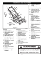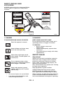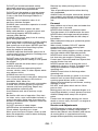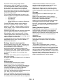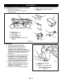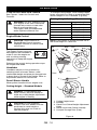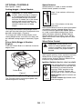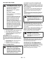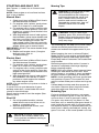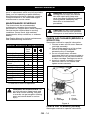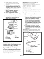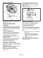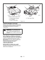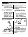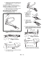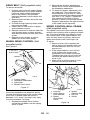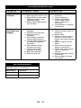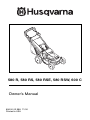
1
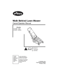
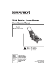
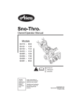
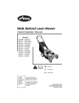
580 R, 580 RS, 580 RSE, 580 RSW, 600 C
Owner’s Manual
606 00 02 98A 11/00
Printed in USA
2
CONTROLS AND FEATURES
1
12
11. Poignée du démarreur
manuel
12. Commande de
l’entraînement des roues
(tondeuses autotractées)
13. Déflecteur à paillis Mulch
14. Commande des gaz
(modèle professionnel)
15. Trous de réglage du
guidon
16. Indicateur de vitesse
2
14
11
3
8
10
16
9
7
13
15
7
5
4
6
Figure 1
ENGLISH
1. Engine Control
2. Ignition Switch (Electric
Start Models)
3. Speed Selector (Selfpropelled)
4. Primer (Briggs Engine)
5. Side Discharge Cover
6. Side Discharge Deflector
7. Cutting Height Levers (2
Rear Wheel Adjusters, 2
Front Wheel Adjusters)
8. Rear Door
9. Adjustable and Folding
Handlebars
10. Grass Bag
11. Recoil Starter Handle
12. Wheel Drive Control
(Self-Propelled)
13. Mulch Plug
14. Throttle Control (Robin
Engines)
15. Handlebar Adjustment
Holes
16. Speed Indicator (Selfpropelled)
OM0033
FRANÇAIS
1. Commande moteur
2. Commutateur de contact
(Modèles à démarreur
électrique)
3. Sélecteur de vitesse
4. Poire d’amorçage
5. Plaque de fermeture
latétale
6. Déflecteur de décharge
latérale
7. Leviers de hauteur de
coupe (réglage par les
roues)
8. Trappe arrière
9. Guidon réglable et pliable
10. Sac à herbe
ESPAÑOL
1. Control del motor
2. Control del arranque
eléctrico (modelos de
arranque eléctrico)
3. Selector de velocidad
4. Cebador
5. Cubierta de la descarga
lateral
6. Deflector de la descarga
lateral
7. Palancas de la altura de
corte (ajustadores de la
rueda)
8. Puerta trasera
9. Manillares ajustables y
plegables
10. Bolsa de recolección del
césped
11. Manilla de arranque de
retroceso
12. Control de la transmisión
de la rueda
(autopropulsión)
13. Tapón Mulch
14. Control del acelerador
(profesional)
15. Agujeros para el ajuste
del manillar
16. Indicador de velocidad
WARNING
The engine exhaust from this product
contains chemicals known to the State
of California to cause cancer, birth
defects or other reproductive harm.
3
TABLE OF CONTENTS
Controls and Features . . . . . . . . . . . . . 3
Introduction . . . . . . . . . . . . . . . . . . . . . . 4
Safety . . . . . . . . . . . . . . . . . . . . . . . . . . . 5
Assembly . . . . . . . . . . . . . . . . . . . . . . . . 9
Operation . . . . . . . . . . . . . . . . . . . . . . . 10
Maintenance . . . . . . . . . . . . . . . . . . . . 14
Service and Adjustments . . . . . . . . . .
Storage . . . . . . . . . . . . . . . . . . . . . . . . .
Troubleshooting . . . . . . . . . . . . . . . . .
Accessories . . . . . . . . . . . . . . . . . . . . .
Specifications . . . . . . . . . . . . . . . . . . .
Warranty . . . . . . . . . . . . . . . . . . . . . . . .
18
21
22
22
23
24
INTRODUCTION
THE MANUAL
PRODUCT REGISTRATION
Before operation of unit, carefully and
completely read your manuals. The contents
will provide you with an understanding of
safety instructions and controls during normal
operation and maintenance.
All reference to left, right, front, or rear are
given from the operation position, facing the
direction of forward travel.
Please fill out and return the Warranty
Registration Card to Husqvarna. This card
activates the warranty. Claims meeting
requirements during limited warranty period
will be honored.
SERVICE AND REPLACEMENT
PARTS
When ordering replacement parts or making
service inquiries, know the Model and Serial
numbers of your unit and engine.
Numbers are located on the product
registration form in the unit literature package.
They are also printed on a serial number label,
located on the frame of your unit (Figure 2).
UNAUTHORIZED REPLACEMENT
PARTS
Use only Husqvarna replacement parts. The
replacement of any part on this vehicle with
anything other than a Husqvarna authorized
replacement part may adversely affect the
performance, durability, or safety of this unit
and may void the warranty. Husqvarna
disclaims liability for any claims or damages,
whether warranty, property damage, personal
injury or death arising out of the use of
unauthorized replacement parts.
DEALER DELIVERY
Serial Number
Label
Figure 2
OM0400
• Record Unit Model and Serial numbers here
• Record Engine Model & Serial numbers here
Dealer should:
1. Check to make sure all assembly and
adjustments have been properly
completed.
2. Fill out Original Purchaser Registration
Card and return the card to Husqvarna.
3. Explain Husqvarna Limited Warranty
Policy.
4. Explain recommended lubrication and
maintenance. Advise customer on
adjustments. Remind customer to
change oil in 4 cycle engine crankcase
after first two (2) hours of operation.
5. Instruct customer on controls and
operation of unit. Discuss and
emphasize the Safety Precautions.
Give customer Owner/Operator, Parts,
and Engine manuals. Advise customer
to thoroughly read and understand
them.
GB - 4
DISCLAIMER
Husqvarna reserves the right to discontinue,
make changes to, and add improvements
upon its products at any time without public
notice or obligation.The descriptions and
specifications contained in this manual were in
effect at printing. Equipment described within
this manual may be optional. Some
illustrations may not be applicable to your unit.
SAFETY
SAFETY ALERTS
PRACTICES AND LAWS
Look for these symbols to point out
important safety precautions. They
mean:
Attention!
Personal Safety Is Involved!
Become Alert!
Practice usual and customary safe working
precautions, for the benefit of yourself and
others. Understand and follow all safety
messages. Be alert to unsafe conditions and
the possibility of minor, moderate, or serious
injury or death. Learn applicable rules and
laws in your area.
REQUIRED OPERATOR TRAINING
Obey The Message!
Original purchaser of this unit was instructed
by the seller on safe and proper operation. If
unit is to be used by someone other than
original purchaser; loaned, rented or sold,
ALWAYS provide this manual and any needed
safety training before operation.
The safety alert symbols above and signal
words below are used on decals and in this
manual.
Read and understand all safety messages.
DANGER: IMMINENTLY
HAZARDOUS SITUATION! If not
avoided, WILL RESULT in death or
serious injury.
WARNING: POTENTIALLY
HAZARDOUS SITUATION! If not
avoided, COULD RESULT in death or
serious injury.
CAUTION: POTENTIALLY
HAZARDOUS SITUATION! If not
avoided, MAY RESULT in minor or
moderate injury. It may also be used
to alert against unsafe practices.
NOTATIONS
NOTE: General reference information for
proper operation and maintenance practices.
IMPORTANT: Specific procedures or
information required to prevent damage to unit
or attachment.
GB - 5
SAFETY DECALS AND
LOCATIONS
ALWAYS replace missing or damaged Safety
Decals. Refer to Figure 3 for Safety Decal
locations.
1
CAUTION
• BAG IS SUBJECT TO WEAR AND
DETERIORATION.
• CHECK BAG FEQUENTLY, REPLACE WHEN
NECESSARY.
• Read the operator's manual.
• Keep children and others away from unit while operating.
• Never direct discharge toward other people. Thrown
objects can cause injury.
• Do not operate mower unless guards are in operating
position or entire bagger is attached.
• Keep safety devices (guards, shields, switches, etc.) in
place and working.
• Go across slopes, not up and down.
• Look down and behind before and while moving backward.
• USE ORIGINAL BAG TO COMPLY WITH SAFETY
SPECIFICATIONS.
PRECAUCION
• LA BOLSA ESTA SUJETA A DESGASTE Y
DETERIORO.
• REVISAR LA BOLSA FREQUENTAMENTE,
POUR EVITER LES BLESSURES GRAVES OU LA MORT
• Lire le manuel de l'utilisation.
• Éloigner les enfants et toute autre personne pendant le
fonctionnement de la machine.
• Ne jamais décharger directement en direction de quelqu’un.
Des particules projetées peuvent provoquer des blessures.
• Ne pas utiliser la tondeuse sans garant et sans sac
totalement attaché.
• Maintenez toujours en place tous les elements de securite
(protecteurs, interupteurs, etc.).
• Tondez le long des pentes, jamais de haut en bas ou
inversement.
• Regardez derriere et sur les cotes lorsque vous reculez.
Y REEPLAZARLA SI ES NECESARIO.
• USAR BOLSAS ORIGINAL PARA CUMPLIR CON
LAS ESPECIFICACIONES DE SEGURIDAD.
ATTENTION
• LE SAC EST SOUMIS À L’USURE ET A LÀ
DÉTÉRIORATION.
• VÉRIFIER LE SAC FRÉQUEMMENT. LE
PARA EVITAR DAÑOS SERIOS O LA MUERTE
• Leer el manual del operador.
• Mantenga la unidad alejada de los niños u otras personas
cuando esté en funcionamiento.
• Nunca dirija la descarga hacia otras personas, a que los
objetos lanzados pueden provocar lesiones.
• No poner en funcionamiento la máquina a menos que las
guardas estén en posición de funcionamiento o la
embolsadora entera esté conectada.
• Mantenga artefactos de seguridad (defensas, protectores,
interruptores, etc.) en su lugar y trabajando.
• Transversa pendientes, no subir ni bajar.
• Mire hacia abajo y detras antes y durante retroceso.
REMPLACER AU BESOIN.
• UTILISER UN BAC D’ORIGINE CONFORME
AUX NORME DE SECURITE.
2
DANGER / PELIGRO
TO AVOID SERIOUS INJURY OR DEATH
Do not operate mower
unless guards are in
operating position or
bagger is attached.
DANGER
EL
OD
M
KEEP HANDS and FEET AWAY
D
IE
IF
RT RAM
CE PROG
BY
IN
DE
PE
SP
ND
ON
SO
EN
RED
T
BY
LA
OUTDOOR POWER EQUIPMENT INSTITUTE
BO
07742400B
3
RA
TO
RY
ANSI B71.1 - 1998 SAFETY STANDARDS
MEETS C.P.S.C. BLADE
SAFETY REQUIREMENTS
C
00
25
74
07
Figure 3
OM0434
1. DANGER
2. DANGER
TO AVOID SERIOUS INJURY OR DEATH
KEEP HANDS AND FEET AWAY
Do not operate mower unless guards are in
operating position or bagger is attached.
Read the operator’s manual.
3. CAUTION!
•
OL1801
Keep children and others away
from unit while operating.
•
•
OL4370
Never direct discharge toward
other people. Thrown objects can
cause injury.
OL0910
Do not operate mower unless
guards are in operating position or
entire bagger is attached.
OL4540
Keep safety devices (guards,
shields, switches, etc.) in place
and working.
OL3030
•
Go across slopes, not up and down.
•
Look down and behind before and
while moving backwards.
Bag is subject to wear and
deterioration.
Check bag frequently, replace when
necessary.
Use original bag to comply with safety
specifications.
SAFETY RULES
Operational
Inspect unit and work area before operation.
Clear work area of objects which might be
picked up and thrown. Remove all stones,
sticks, wires, and other foreign objects. Tall
grass can hide obstacles.
Only Trained Adults may operate unit. Training
includes actual operation.
Keep equipment in good condition.
ALWAYS keep discharge cover in place.
NEVER operate the engine with the Rear
Door open unless the Grass Bag is in place.
When mulching, the Side Discharge Opening
Cover must be installed and the Rear Door
fully closed whenever the engine is operating.
GB - 6
DO NOT pull mower backwards unless
absolutely necessary. Look down and back
before and while moving backwards.
DO NOT start the engine or operate mower
unless either the Side Discharge Opening
Cover or the Side Discharge Deflector is
installed.
Keep the area of operation clear of all
persons, children and pets.
ALWAYS clear area before operation to avoid
thrown objects.
Stop mower if anyone enters the area.
Keep safety devices or guards in place and
functioning properly. NEVER modify or
remove safety devices.
ALWAYS keep hands away from all rotating
parts during operation.
Do not put hands or feet near or under rotating
parts. Keep clear of the discharge opening
and mower pan at all times. NEVER open the
Rear Door without the Grass Bag in place
when the engine is operating.
ALWAYS keep feet and hands away from all
rotating parts during operation. Rotating parts
can cut off body parts.
DO NOT mow at too fast a rate. DO NOT
change engine governor setting or over-speed
the engine.
ALWAYS operate unit when there is good
visibility and light.
Use extra care when approaching blind
corners, shrubs, trees, or other objects which
may obscure vision.
ALWAYS be sure of your footing.
Do not operate mower in wet grass. Always be
sure of your footing. Keep a firm hold on
handlebar. Walk, never run.
If equipment vibrates abnormally, stop engine
at once, wait for moving parts to stop and
remove wire from spark plug. Repair any
damage before restarting unit.
Avoid uneven work areas and any rough
terrain.
Be familiar with area of operation. Stay alert
for holes, rocks, roots, and hidden hazards in
area of operation. Keep away from drop-offs,
ditches or embankments. Operator could lose
footing or balance.
DO NOT operate on steep slopes.
NEVER leave unit unattended on a slope.
Chock wheels if parking on a slope.
Mow across the face of slopes, never up and
down. Be especially cautious when changing
direction on slopes.
Remove key when parking (electric start
models).
Take all possible precautions when leaving
unit unattended.
ALWAYS shut off engine, remove key (electric
start models) and remove spark plug wire to
prevent accidental starting or unauthorized
use.
Personal
Keep children out of work area and under the
watchful care of an adult.
NEVER allow children to operate mower.
Turn the mower off if children enter the area.
NEVER direct discharge toward bystanders.
The operator is responsible for the safety of
bystanders.
Wear adequate safety gear, protective gloves
and footwear.
Wear sturdy footwear. DO NOT operate
mower barefoot or when wearing open
sandals or canvas shoes.
Always wear safety goggles or safety glasses
with side shields when operating mower.
NEVER wear loose clothing, jewelry or long
hair that may get caught in rotating parts.
Protect eyes, face and head from objects that
may be thrown from unit.
NEVER operate after or during the use of
medication, drugs or alcohol. Complete and
unimpaired attention is required when
operating unit.
ALWAYS stand clear of discharge when
operating unit.
Do not operate mower on gravel or on loose
material such as sand. Stop mower when
crossing gravel drives, walks, or roads.
Objects may be picked up and thrown, causing
damage or injury.
DO NOT touch parts which are hot. Allow
parts to cool.
Moving parts can cut or amputate fingers or a
hand. Wrap blade(s) or wear gloves to service.
ALWAYS keep hands away from all pinch
points.
Fumes from the engine exhaust can cause
death or serious injury. DO NOT run engine in
an enclosed area.
Service and Adjustments
NEVER attempt to make any adjustments to
unit while engine is running. Stop engine,
remove key (electric start models) and wait for
all moving parts to stop before servicing
(except where specifically recommended).
GB - 7
DO NOT make cutting height wheel
adjustments while the engine is running.
On self-propelled models, releasing wheel
drive control must stop mower’s forward
movement. If this feature fails to operate,
disconnect spark plug wire and repair before
using unit. Wheel drive must be disengaged
when starting engine.
Fuel is highly flammable and its vapors can
explode. ONLY use approved fuel containers.
• NO Smoking!
• NO Sparks!
• NO Flames!
• Allow engine to cool before filling fuel
tank.
Check fuel supply before starting engine.
DO NOT fill gasoline tank indoors, when
engine is running, or while engine is still hot.
Allow engine to cool several minutes before
removing fuel cap.
Replace gasoline tank cap securely and clean
up any spilled fuel before starting engine.
Stop engine, wait for moving parts to stop,
remove ignition wire and secure away from
spark plug before attempting to: unclog, repair,
adjust, inspect or clean unit.
To reduce fire hazard and overheating, keep
equipment free of grass, leaves, debris or
excessive lubricants.
ALWAYS block wheels and know all jack
stands are strong and secure and will hold
weight of unit during maintenance.
Check grass bag for wear, damage, and/or
deterioration. Replace only with Husqvarna
original equipment replacement part for safety.
Storage
Allow engine to cool before storing in any
enclosure.
Refer to Storage Section of this Owner’s
Manual for important instructions if unit is to
be stored for extended periods.
ALWAYS clean unit before extended storage.
See engine manual for proper storage.
DO NOT store unit inside a building with fuel in
the fuel tank where any ignition sources are
present.
Safety Interlock System
Engine/Blade Control feature on mower will
cause engine and blade to stop whenever
operator releases control on handlebar. If
feature fails to operate, disconnect spark plug
wire and adjust or have it repaired before
using unit.
Accessories
Use only accessories which have been
approved by Husqvarna and are properly
installed.
Battery (electric start models)
Spark Arrestor
Avoid Electric Shock. DO NOT remove wire
from spark plug while engine is running. Do
not put battery in fire or mutilate.
Explosive Gases! Poisonous battery fluid
contains sulfuric acid. Contact with skin, eyes
or clothing can cause severe chemical burns.
No flames, No sparks, No smoking, near
battery.
ALWAYS wear safety glasses and protective
gear near battery.
ALWAYS KEEP BATTERIES OUT OF REACH
of children.
This product is equipped with an internal
combustion engine. DO NOT use on or near
any unimproved, forest or brush covered land
unless the exhaust system is equipped with a
spark arrestor meeting applicable local, state
or federal laws. A spark arrestor, if used, must
be maintained in effective working order by the
operator. See your Husqvarna Dealer or
engine manufacturer’s service center.
Maintenance
Follow engine manufacturer’s safety
instructions when servicing engine.
Keep all nuts, bolts, and screws tight and be
sure equipment is in safe working condition.
Check all hardware at regular intervals,
especially blade attachment bolts.
Use only replacement parts designed for your
unit. See your Husqvarna Dealer.
Worn out mufflers are more than just a noise
nuisance and should be replaced immediately.
Continued use could result in fire or explosion.
GB - 8
ASSEMBLY
TO REMOVE UNIT FROM CARTON
1. Cut off top of carton.
2. Remove front and rear inserts and
literature pack.
3. Cut out back of carton and roll unit out.
4. Remove protective packaging
materials.
1
2
3
OM0340
5
Lit
er
Paatur
ck e
OM0320
OM0311
OM0350
1.
2.
3.
4.
5.
6.
Mower Unit
Discharge Chute
Grass Bag
Grass Bag Frame
Literature Pack
Battery Charger (electric start
models)
6
4
OM0560
OM0330
Figure 4
ASSEMBLY
1. Unfold and adjust handlebar.
2. Self propelled units: The Speed
Selector rod is shipped on the
handlebar with hardware in position.
Remove hair pin, insert bent end of rod
through hole in swivel of speed control
bell crank, and retain with hair pin
(Figure 5).
3. Assemble grass bag onto bag frame.
4. Configure mower for bagging, side
discharge or mulching. See Mower
Configurations in Operation Section.
5. Fully charge battery (electric start
models). See Service & Adjustments.
6. Check the Engine/Blade Control
feature. Engine and blade must stop
within 3 seconds whenever control
handlebar is released.
7. Fill fuel tank. See Operation Section.
1
3
2
OM0300
1. Speed Selector Rod
2. Hair pin
3. Speed Control Bell Crank
Self propelled units
Figure 5
GB - 9
OPERATION
CONTROLS AND FEATURES
To change cutting height, move cutting height
levers one notch at a time on each wheel until
desired height of cut is obtained. (Figure 6)
See Figures 1 and 6 for Controls and
Features.
Cutting Height Settings Chart
WARNING: DO NOT attempt to start
your engine at this time. Familiarize
yourself with controls to see what
they do and how they work.
Thoroughly read and understand
entire Operators Manual first.
Engine/Blade Control
Notch
LOW
2
3
4
5
HIGH
Cut grass length
1" (25 mm)
1-3/8" (35 mm)
1-3/4" (45 mm)
2-1/4" (57 mm)
2-3/4" (70 mm)
3-1/4" (83 mm)
NOTE: Each wheel on mower must be set at
the same height for a level cut.
CAUTION: Check function of
Engine/Blade Control regularly.
Improper function of control could
cause injury.
High
Low
The Engine Control must be
held against the handlebar in
order to start the engine as
OM0450
well as during mowing
operations to keep the engine
running.
Releasing the control during operation stops
the engine and blade.
Low
High
1
2
2
1
Handlebar
Handlebar adjusts to four positions by
selecting holes in braces. Select a safe,
comfortable height and place pin through hole
in brace that is closest to that height. Refer to
Adjustment Section for instructions.
OM0190
OM0160
Rear
Front
5
4
Recoil Starter Handle
When pulled, handle will turn engine over.
Cutting Height – Standard Models
3
DANGER: To avoid inadvertent
blade contact, NEVER attempt to
make any cutting height adjustment
while engine is running.
OM0180
Front Swivel
1. Cutting Height Lever
2. Notches
3. Clevis Pin & Swivel Height Adjustment
Holes
4. Swivel Lock Hole (Swivel Locked)
5. Linchpin Storage Hole (Free)
CAUTION: On self-propelled
models, both rear wheels must be
positioned at same height or
traction drive may not clutch or
operate properly.
Figure 6
GB - 10
OPTIONAL CONTROLS
Speed Selector
See Figures 1 and 6.
Speed Selector is used to select variable
forward travel speeds of mower.
Cutting Height – Swivel Models
CAUTION: On swivel wheel
models, when mowing on slopes it
is recommended that the linchpin
be positioned through the swivel
lock hole. If wheels are in the swivel
position and control handles are
released the mower may “free roll”
downhill. Never mow on steep
slopes.
To change front wheel cutting height, insert
clevis pin into the holes that correspond to the
desired cutting height. (Figure 6).
To change rear wheel cutting height, move
cutting height levers one notch at a time until
the desired cutting height is obtained. (Figure
6).
Primer Bulb (Briggs & Stratton
Engine)
High –Push selector all the way
forward.
Low –Pull selector all the way
rearward.
With Speed Selector set at a slow travel speed
and engine running, engage Wheel Drive
Control. Increase speed with Speed Selector
to a safe, comfortable walking pace. Once
speed has been selected, Speed Selector
should remain in this position. If not, adjust
speed control bell crank spring tension. (See
Adjustments).
OM0480
Wheel Drive Control
CAUTION: Holding Wheel Drive
control of self-propelled models
against handlebar, when attempting
to start mower, will propel mower
forward.
Push the Primer Bulb in to add fuel for easier
engine start.
With engine running, slowly squeeze and hold
Wheel Drive Control against handlebar to
propel mower forward. Release Wheel Drive
Control to stop forward motion.
Ignition Switch (electric start models)
1
Primer Bulb
Figure 7
OM0570
2
Throttle/Choke (Robin Engine)
The Throttle controls the engine speed and
chokes engine for starting.
OM1000
GB - 11
The Ignition Switch is operated by
a removable Key. To start the unit,
the switch is turned clockwise
from the "RUN" position to the
"START" position. The key will
spring back to the "RUN" position.
RUN Position (1): All controls are
operable.
START Position (2): Starter turns
over the engine.
FILLING FUEL TANK
WARNING: EXPLOSIVE VAPORS
and FLAMMABLE FUEL can result
in serious injury or death. Handle
fuel with care. ALWAYS use an
approved fuel container.
No Smoking! No Lighted
Materials!
No Open Flame!
Allow engine to cool before
maintenance.
Gasoline is highly flammable and
must be handled with care. Allow
engine to cool several minutes
before removing fuel tank cap.
Never fill tank when engine is
running or is hot from operation. DO
NOT allow open flame, matches, or
smoking in area. DO NOT overfill.
Allow about 1/4" of tank space for
fuel expansion. Wipe up any spills
and allow vapors to dissipate before
starting engine. Use approved
(Red) gasoline container.
To add fuel to Fuel Tank:
1. Put unit in open or well-ventilated area.
2. Stop engine and allow to cool.
3. Clean Fuel Cap and surrounding area
to prevent dust, dirt and debris from
entering Fuel Tank.
4. Remove Cap.
IMPORTANT: DO NOT use gasohol or
gasoline containing alcohol because alcohol
will cause internal parts to deteriorate. See
Engine Manual for correct type and grade of
fuel.
5. Fill fuel tank. (See Specifications for
tank capacity.)
6. Replace Fuel Cap and tighten.
7. ALWAYS clean up any spilled fuel.
Mower Configurations
CAUTION: DO NOT operate mower
unless either side discharge
opening cover or side discharge
deflector is installed. Objects may
be picked up and thrown causing
damage or personal injury. Never
operate engine with rear door open
unless grass bag is in place.
To configure your mower for bagging, side
discharge or mulching, proceed as follows:
Bagging: Lift rear door, place bar of grass bag
frame on lip of mounting flange and lower rear
door. If necessary, lift rear of grass bag frame
to lock in position.
Be sure there are no openings between bag
and mounting surface after installing bag. If
necessary clear bag mounting surface of
debris.
To remove grass bag, lift rear door. Then with
handle, lift bag up off mounting flange and
close rear door.
CAUTION: Objects may be thrown.
Check grass bag frequently for wear
or deterioration. Replace worn or
damaged bag with Husqvarna
original equipment replacement bag
only.
Side Discharge: With grass bag removed,
remove two lock nuts and washers that secure
side discharge opening cover to mower. Lift
cover to free tabs from slots and remove cover
from mower.
Position holes in side discharge deflector over
studs on mower. Place tab on rear edge of
deflector onto edge of discharge opening.
Secure deflector with cover hardware.
WARNING: NEVER direct
discharge of material toward
bystanders. Do not allow anyone
near equipment while unit is in
operation.
Mulching: Remove grass bag and install side
discharge opening cover. Open rear door and
insert plug with the beveled face to the left.
Rear door should close flush.
STOPPING IN AN EMERGENCY
To stop the mower in an emergency situation,
release both the engine/blade control bail and
the wheel drive control bail from the
handlebar. Allow all moving parts to stop
before leaving operator’s position.
GB - 12
STARTING AND SHUT OFF
Mowing Tips
See Figures 1, 4 and 6 for all Controls and
Features.
NOTE: Start engine on a hard level surface
that is free of debris.
CAUTION: On swivel wheel models,
when mowing on slopes it is
recommended that the linchpin be
positioned through the swivel lock
hole. If wheels are in the swivel
position and control handles are
released the mower may “free roll”
downhill. Never mow on steep
slopes.
Manual Start
1. Check each item in Before Each Use in
the Maintenance Schedule.
2. For engines with a primer, push primer
bulb 2 or 3 times for a cold engine.
3. For engines with a choke, place throttle
control in the choke position. Once the
engine has started, place throttle in the
high speed detent.
4. With engine/blade control held against
the handlebar, grasp starter handle and
pull rope out slowly until it pulls harder.
This is the compression stroke. Let
rope rewind slowly. Then pull rope with
rapid continuous full arm stroke to start
engine. Allow rope to rewind slowly.
IMPORTANT: DO NOT let starter handle snap
against engine.
5. Repeat until engine starts. (If engine
does not start, refer to
Troubleshooting.)
Electric Start
1. Check each item in Before Each Use in
the Maintenance Schedule.
2. For engines with a primer, push primer
bulb 2 or 3 times for a cold engine.
3. For engines with a choke, place throttle
control in the choke position. Once the
engine has started, place throttle in the
high speed position.
4. With engine/blade control held against
the handlebar, turn the key to “Start”
position to crank engine and release
key when engine starts.
NOTE: It is not necessary to prime or choke a
warm engine.
If starter will not cycle because of grass
buildup under deck, rotate blade with recoil
starter to clear blockage.
Recoil may be used to start the engine (See
Manual Start).
Shut Off
1. On self-propelled models, release
wheel drive control and allow unit to
come to a complete stop.
2. Release engine/blade control, and
allow engine to cool.
CAUTION: If clog or obstruction
prevents grass flow, release Engine/
Blade Control and disconnect spark
plug wire before attempting to clear
away any clogs.
The following tips will help you to mow safely,
achieve maximum performance from your
mower and maintain the appearance of your
lawn.
When bagging, be sure to release Engine/
Blade Control to stop engine and blade before
attempting to remove and empty grass bag.
Empty bag before it becomes overloaded and
clogs mower.
Restarting engine will be easier if mower is
allowed to completely discharge clippings
before stopping engine.
NOTE: Be sure to empty grass bag and clean
mower pan after each use. DO NOT allow
grass clumps or a coating of grass and debris
to collect inside of grass bag or mower pan.
NOTE: Avoid operating over bare ground with
only patches of grass. This causes dirt and
grass to collect under pan surface and in grass
bag.
Prevent debris buildup and allow proper air
circulation. Remove grass bag from mower,
wash bag with hose and allow to dry.
Mulching Tips
For best mulching performance, set mower
height to 3 inches. If grass is very tall, do not
cut more than 1 inch of grass per cutting.
Cut grass only when dry, not when it is wet
from dew, rain, or watering. Wet grass tends to
pack inside the mower pan. If cut grass does
not disperse evenly, it is probably because too
much grass is being removed per cutting, the
grass is too wet, or the travel speed is too fast.
CAUTION: ALWAYS remove key
(electric start models) when not in
use to prevent accidental starting or
unauthorized use.
GB - 13
MAINTENANCE
Husqvarna Dealers will provide any service,
parts or adjustments which may be required to
keep your unit operating at peak efficiency.
Should engine service be required, contact a
Husqvarna dealer or an authorized engine
manufacturer's service center.
WARNING: Stop engine, wait for
moving parts to stop, and remove
wire from spark plug (keep wire
away from plug to prevent accidental
starting) before attempting any
lubrication or maintenance
procedures.
MAINTENANCE SCHEDULE
The chart shows the recommended
maintenance schedule that should be
performed on a regular basis. More frequent
service may be required due to working
conditions (heavy loads, high ambient
temperatures, dusty conditions, or airborne
debris).
See Engine Manual for further maintenance
and troubleshooting information.
MAINTENANCE SCHEDULE
Service Performed
Check Air Cleaner
Check Engine Oil
Check Mower Blade
Check Drive Belt
Check Engine/Blade
Control
Change Engine Oil
Check Grass Bag
Check Drive Control
General Lubrication
Check Fasteners
Check Spark Plug
Check Engine
Cooling
Check Muffler
*
Before
Each
Use
•
•
•
•
•
•
*•
25
100
•
CAUTION: DO NOT touch engine
parts which are hot from operation.
Allow parts to cool before servicing.
CHECK AIR CLEANER (BRIGGS &
STRATTON)
See engine manual for specific information.
1. Loosen screws and lift cover. Remove
cartridge assembly.
2. Tap cartridge gently on a flat surface.
Do not oil cartridge. Replace if
extremely dirty or damaged.
3. Do not use petroleum solvents
(kerosene) which will cause cartridge to
deteriorate. Do not use pressurized air
to clean cartridge. Damage can result.
4. Install air cleaner assembly in base.
Reinstall cover on air cleaner and
tighten screws securely.
•
4
3
•
•
•
•
•
•
2
After first 2 Hours of operation
WARNING: ROTATING PARTS can
cut off body parts. Keep hands and
feet away. Loose clothing, long hair
or scarves can get caught in rotating
parts and cause death or serious
injury.
1
OM0580
1. Base
2. Cartridge
3. Cover
4. Screws
Figure 8
CHECK AIR CLEANER (ROBIN)
See engine manual for specific information.
GB - 14
1. Loosen wing bolt and lift cover.
Remove pre-cleaner and cartridge
assembly.
2. Wash pre-cleaner in liquid detergent
and water. Allow to dry thoroughly.
Saturate pre-cleaner in oil (SAE #30).
Squeeze to remove excess oil. Do not
wring. Replace if extremely dirty or
damaged.
3. Tap cartridge gently on a flat surface.
Do not oil cartridge. Replace if
extremely dirty or damaged.
4. Do not use petroleum solvents
(kerosene) which will cause cartridge to
deteriorate. Do not use pressurized air
to clean cartridge. Damage can result.
5. Place the pre-cleaner on the cartridge.
6. Install air cleaner assembly in base.
Reinstall cover on air cleaner and
tighten wing bolt securely.
7
6
5
4
3
2
1
IMPORTANT: DO NOT overfill. Be sure
engine is level when adding oil.
See Engine Manual for detailed instructions.
CHECK MOWER BLADE
See figures 10 and 11.
Check blade for wear.
Check blade mounting: blade must be secure
and cap screw torqued to 37.5 - 50 ft. lbs.
(lock washer should be fully compressed by
cap screw).
When blade needs sharpening:
1. Block blade to prevent rotation.
2. Remove cap screw, lock washer and
blade from shaft.
3. Sharpen both ends of blade at original
angle (25°), removing equal amounts of
material from each end to maintain
proper blade balance. New blades are
balanced to within 1.3 in. oz. at factory.
DO NOT grind around corner at tip of
blade. If cutting edge of blade cannot
be sharpened in a straight line to within
1/8 of an inch of its end, replace blade
with Husqvarna replacement blade
only.
4. Install blade, lock washer and cap
screw. Blade must be secure and cap
screw torqued to 37.5 - 50 ft. lbs. (lock
washer should be fully compressed by
cap screw).
IMPORTANT: If mower is used under sandy
soil conditions, replace blades when air lifts
become eroded.
5
4
OM0590
1.
2.
3.
4.
Base
Packing
Cartridge
Pre-cleaner
3
5. Cover
6. Grommet
7. Wing Bolt
Mulching
Blade
1
2
Figure 9
OM0230
4
CHECK ENGINE OIL
IMPORTANT: Change engine crankcase oil
after first two (2) hours of operation.
Thereafter, change oil every twenty five hours
of operation (more often in dusty, dirty
conditions). Refer to Engine Manual for oil
type and grade and detailed instructions.
Engine Oil Check and Change
The engine crankcase oil should be checked
before each use or every five (5) hours of
operation. Oil level MUST be maintained in
safe operating range on dipstick at all times or
engine damage will result.
GB - 15
3
OM0240
2
1.
2.
3.
4.
5.
1
Standard Blade
Cutting Edge
Square Corner
Air Lift Erosion
Air Lift
Reverse Lift
Figure 10
CHECK DRIVE BELT
When lubricating for the first time, clean all
components thoroughly before applying
grease. Reapply grease to the lube fittings
every 25 hours.
NOTE: Linchpin must be in the swivel lock
hole while lubricating.
1
2
2
1
4
3
OM0250
1. Blade
2. Cap Screw, Lock
Washer & Flat Washer
3. Drive Belt
4. Idler
1. Grease Fitting
2. Swivel Lock Hole
Figure 11
OM0180
Figure 12
Check drive belt for wear or damage. Replace
belt if worn or damaged. See Service and
Adjustments.
CHECK ENGINE/BLADE
CONTROL
The engine/blade control must stop the engine
and blade within 3 seconds after the bail is
released. If the engine or blade continues to
run, adjust or repair control immediately. See
Adjustments.
CHECK GRASS BAG
Check bag for wear or damage. Keep bag
clean and dry. Replace only with Husqvarna
original equipment replacement bag.
CHECK DRIVE CONTROL (Self
propelled units)
Check operation of drive control. The drive
must disengage completely when the bail
handle is released. Adjust bail travel if
necessary. See Adjustments.
CHECK FASTENERS
Check all fasteners for proper tightness. Pay
special attention to blade hardware and all
guards, shields and safety devices.
CHECK SPARK PLUG
Spark plug should be cleaned (or replaced) if
necessary and gap reset to .030" every 100
hours of operation or yearly, whichever comes
first.
To clean:
1. Remove debris from area around spark
plug base.
2. Remove spark plug from engine.
3. Scrape and wash spark plug with a
commercial solvent. DO NOT blast
clean.
4. Replace spark plug.
NOTE: Sparking can occur if wire terminal
does not fit firmly on spark plug. Replace
terminal if damaged.
GENERAL LUBRICATION
Mower does not require any lubrication. Wheel
assemblies are designed for long life without
additional lubrication.
NOTE: The 600C does have lube fittings on
drive mount for use in commercial
applications. Lubricate as needed.
Swivel Lubrication (swivel units)
See Figure 12.
GB - 16
1
1
4
4
2
2
3
OM0550
3
OM0570
Robin
Briggs & Stratton Intek OHV
1. Oil Fill Cap & Dipstick
2. Air Cleaner
3. Spark Plug & Wire
4. Fuel Cap & Tank
Figure 13
CHECK ENGINE COOLING
Engine is air cooled. Air must circulate freely
around engine from Air Intake to cooling fins
on cylinder head and block to prevent
overheating.
WARNING: HOT SURFACES can
cause death or serious injury. DO
NOT TOUCH parts which are hot
from operation. ALWAYS allow parts
to cool.
Every 100 hours of operation or yearly (more
often if conditions require) remove cooling
shrouds and clean cooling fins. Clean external
surfaces of engine of dust, dirt and oil deposits
which can contribute to improper cooling.
IMPORTANT: DO NOT operate engine with
blower housing removed or engine
overheating damage will result.
CHECK MUFFLER
Check muffler for cracks, wear, or other
damage. Worn out mufflers should be
replaced immediately. Continued use could
result in fire or explosion.
GB - 17
SERVICE AND ADJUSTMENTS
SERVICE POSITION
WARNING: ACCIDENTAL ENGINE
START UP can cause death or
serious injury. ALWAYS stop engine,
remove key (electric start models),
wait for moving parts to stop and
remove wire from spark plug before
adjusting or servicing.
Place unit on a flat level surface. ALWAYS
stop engine. Assure unit is secure and will not
tip over. Strap and clamp onto bench if
needed.
CAUTION: Before unit is tipped up,
remove enough fuel so that no spills
will occur. A piece of plastic bag
may be used to seal fuel tank
opening when tipping mower. To
seal, remove fuel tank cap, cover
fuel tank opening with plastic,
replace and tighten cap securely
before attempting to tip mower. Be
sure to remove plastic before
attempting to operate mower.
IMPORTANT: When tipping to service engine
or unit, use the following service positions for
the brand and type of engine on your mower:
Robin Engines: place handlebar into service
position and tip machine to the rear.
Briggs & Stratton Intek Engines: place
handlebar into handlebar service position and
tip the machine to the left, opposite the
discharge opening.
IMPORTANT: If engine becomes “flooded”
due to tipping, clean air cleaner (See
Maintenance) and remove spark plug, turn
engine over a few times and reinstall spark
plug.
HANDLEBAR
To adjust handlebar height (Figure 15):
1. Place a hole (1-4) at the bottom of the
braces over the pins. On professional
models, use the fasteners to attach one
of the holes at the top (1, 2) and one of
the holes at the bottom (3, 4).
2. For service position, remove braces
from pins, rotate handlebar forward and
place pins into holes of braces.
Professional Brace
1
A handlebar service position is provided for
tipping the unit for cleaning and service
(Figure 14). See Adjustments.
2
Brace
3
4
Storage
Position
Pin
OM0270
Figure 15
BATTERY (Electric Start Models)
To Charge Battery
OM0210
Figure 14
IMPORTANT: DO NOT attempt to “jump start”
mower.
1. Connect battery charger plug to mating
plug on battery (not engine).
2. Plug charger into 110 volt Alternating
Current (A.C.) outlet.
IMPORTANT: Battery charger supplied with
unit is for 110 volt Alternating Current (A.C.)
outlets only.
GB - 18
3. Charge for 24 to 48 hours (battery may
be charged for up to 72 hours with no
harmful effects).
An engine run time of at least 8 hours is
required to charge a fully discharged battery.
To Remove Battery from Unit
1. Remove wing nuts from battery U-bolt.
2. Disconnect battery from wiring.
ENGINE/BLADE CONTROL
No slack
To adjust engine/blade control:
1. Loosen cable nuts away from bracket.
4. Tighten lower
cable nut to 1/
8" (3mm)
below bracket.
Release zbend bracket.
1/8
(3mm”
)
5. Tighten upper
cable nut until
bracket is secure
between cable
nuts.
6. Engage engine/blade control. Measure
distance between middle of z-bend and
cable bracket. Measurement should be
as shown below.
1.325"-1.788"
(3.4 - 4.5 cm)
Figure 16
2. Squeeze z-bend bracket at engine end
of cable toward front of unit and hold in
place.
Briggs & Stratton
Robin
Briggs & Stratton
Robin
1.240" (3.15 cm)
7. If proper measurement cannot be
achieved, contact your local dealer.
3. Pull cable down from bracket until there
is no slack in cable.
GB - 19
DRIVE BELT (Self propelled units)
To remove drive belt:
1. Position right hand rear wheel Height
Adjustment lever in first notch and left
hand rear wheel Height Adjustment
lever in third notch. This provides
clearance between friction wheel and
drive disk.
2. Remove belt from idler, drive disk and
engine pulley.
3. Pull belt through opening under mower
pan and over blade.
4. Check idler for free rotation of pulley
and movement of pivot.
5. Reinstall drive belt in reverse order. Be
sure that belt seats in pulley grooves
with idler positioned on back (flat) side
of belt.
6. Reposition rear wheels so all four
wheels are at the same height.
WHEEL DRIVE CONTROL (Self
propelled units)
See Figure17.
1-1/2" to 2"
(3.8 to 5cm)
2
2. Measure the distance between the
Wheel Drive Control and handlebar at
the handlebar indentation.
3. To obtain the proper adjustment, turn
the cable nuts. Turn clockwise if the
measurement is more than 2" (5cm);
counterclockwise if the measurement is
less than 1-1/2" (3.8cm). Tighten the
nuts against the bracket to lock in
position. If there is not enough thread
length for adjustment, the opposite end
of the cable can be adjusted.
SPEED CONTROL BELL CRANK
(Self propelled units)
The speed control bell crank holds the speed
selector rod in position after a speed has been
set. The spring washers may become loose
with normal wear. If the speed selector rod
does not stay firmly in position, adjust the
speed control bell crank. See Figure 18.
To adjust:
1. Remove cover, fully compress the
helical spring lock washers with lock
nut and then back lock nut off, one
quarter turn.
2. If the speed selector rod is still too
loose, tighten lock nut by small
increments until it holds its position.
Tightening the lock nut too much will
not allow the speed selector rod to
move at all.
3. Align notch in left hand side of cover
with bolt and secure with knob.
4
1
3
2
1
OM0290
1.
2.
3.
4.
4
Traction Cable
Handlebar Indentation
Cable Nuts
Wheel Drive Control
3
5
Figure 17
When the Wheel Drive Control is squeezed
toward the handlebar the extension spring,
located at the bottom end of the traction cable,
must start to extend when the control is
between 1-1/2" and 2" (3.8 and 5 cm) away
from the handlebar. To check:
1. Squeeze the Wheel Drive Control
toward the handlebar until the spring
starts to open.
GB - 20
6
OM0300
1. Lock Nut
2. Helical Spring
Lock washers
3. Speed
Control Bell
Crank
Figure 18
4. Speed
Selector Rod
5. Hair Pin
6. Swivel
STORAGE
WARNING: FLAMMABLE FUEL
and its EXPLOSIVE VAPORS can
cause death or serious injury. DO
NOT store unit with fuel in the fuel
tank inside a building where any
ignition sources are present. Drain
fuel outdoors away from any ignition
source. Allow engine to cool before
storing in any enclosure. Only use
approved fuel containers.
IMPORTANT: NEVER spray unit with water or
store unit outdoors. Water can seep into
sealed bearings, which are sealed against dirt
and debris only, causing reduced component
life. Store mower in a cool, dry, protected
location.
Cleaning
Clean unit thoroughly. Brush dirt and debris off
with a brush. Apply paint or spray lubricant to
exposed metal joints and surfaces. Do not use
abrasives, solvents, or harsh cleaners.
Inspection
Inspect mower for signs of wear or damage.
Order any parts required and make necessary
repairs to avoid delays when beginning use
again.
Keep all nuts, bolts and screws tight and know
unit is in safe working condition. Check all
hardware at regular intervals.
Grass Bag
Remove Grass Bag and clean out all debris
before storage. Grass Bag may be stored in
position on mower. Keep Grass Bag dry during
storage.
Battery
Fully charge battery and store in a cool, dry
location. If the outdoor temperature is
expected to be below freezing for long periods
of time, remove battery from unit and store in a
cool, dry, protected place. Do not allow battery
to freeze. See Service and Adjustments.
Engine
When storing unit for extended periods of
time, remove all fuel from tank and carburetor
(run dry). Refer to Engine Manual.
GB - 21
TROUBLESHOOTING
PROBLEM
PROBABLE CAUSE
CORRECTION
Engine will
not start
1. Fuel tank empty or low.
2. Spark plug wire loose or off.
3. Engine/brake control cable
detached, broken, or not
adjusted properly.
4. Battery discharged (electric
start models).
1. Check fuel level. Fill tank if
necessary.
2. Check connection.
3. Check engine/brake
control cable. Adjust,
repair or replace as
necessary.
4. Charge battery or replace
if necessary.
Self-propelled
drive does not
engage.
1. Traction drive bail not
engaged.
2. Drive belt out of position.
3. Drive belt worn or
damaged.
4. Rear wheels in different
cutting height positions.
5. Friction wheel engagement
not adjusted properly or
damaged.
6. Idler and idler spring
installed incorrectly.
7. Traction drive cable
detached or broken.
8. Bearings damaged.
9. Debris in gear set.
1. Engage traction drive bail.
2. Check drive belt. Adjust as
necessary.
3. Replace belt.
4. Adjust rear wheel cutting
position so that cutting
height is the same on both
sides.
5. Adjust or replace friction
wheel.
6. Check idler and spring.
Adjust as necessary.
7. Check drive cable. Adjust,
repair or replace as
required.
8. Replace bearings.Contact
your Dealer.
9. Remove debris. Contact
your Dealer.
ACCESSORIES
See your authorized Husqvarna dealer to
add these optional accessories.
606 00 00 01
Dethatcher
606 00 00 02
Swivel Wheel
606 00 02 30
Battery Charger
GB - 22
SPECIFICATIONS
Model Number
601 10 00 24 601 10 00 20 601 10 00 21 601 10 00 22 601 10 00 23
Description
580 R
580 RS
580 RSE
580 RSW
600 C
Length - in (cm)
61.5 (156)
Height - in (cm)
38 (96,5)
Width - in (cm)
23 (58,4)
Actual Weight - lbs (kg)
81 (36,7)
97 (44,0)
102 (46,3)
105 (47,6)
118 (53.6)
Cutting Width
21 (53,3)
Cutting Height - in. (cm)
6 Positions: 1.00 - 3.25 (2,5 - 8,3)
Engine, 4 cycle
Briggs & Stratton Intek OHV
Robin
Engine Power Max - HP
4.37 (3,26)
5.3 (3,9)
(kw)
Max Rotation Speed
of Cutting Edge
3100
- RPM (min-1)
Governed RPM
Displacement Cu. In.
(cc)
Cylinder Bore
3000 +/- 100
11.57 (190)
Aluminum
Engine Oil Type
Crank Case Capacity Oz. (Liter)
Oil System
Engine Oil Filter
Spark Plug Gap - in
(mm)
Fuel Type
Fuel Tank Capacity - qt
(Liter)
Primer Bulb
Throttle/Choke Control
Air Cleaner
SAE 30
22 (0,65)
Splash
N/A
0.030 (0,76)
Unleaded
1.6 (1,5)
Standard
N/A
Paper Element
Starting
Differential
Variable Speeds - MPH
(km/hr)
Mower Deck
Adjustable Handlebar
Front Wheel Dia - in (cm)
Rear Wheel Dia - in (cm)
Recoil
Electric/
Recoil
Standard
0-4 (0-6,4)
N/A
N/A
14 Gauge - Stamped Steel
Four Position
7.5 (19,1)
10.5 (26,7)
GB - 23
11.16 (183)
Cast Iron
Sleeve
17 (0,50)
Pressurized
Spin-on
2.0 (1,9)
N/A
Standard
Dual
Element
Recoil
0-3.5 (0-5,6)
GB - 24
The following items are not covered by this warranty:
(1) Normal customer maintenance items which become worn through normal regular use, including, but
not limited to, belts, blades, blade adapters, bulbs, filters, guide bars, lubricants, rewind springs, saw
chain, spark plugs, starter ropes and tines;
(2) Natural discoloration of material due to ultraviolet light;
(3) Engine and drive systems not manufactured by Husqvarna; these items are covered by the respective
manufacturer’s warranty as provided in writing with the product information supplied at the time of pur
chase; all claims must be sent to the appropriate manufacturer;
(4) Lawn and garden attachments are covered by a third party which gives a warranty, all claims for warranty should be sent to the manufacturer; and
(5) Emission Control System components necessary to comply with CARB-95 and EPA regulations which
are manufactured by third party engine manufacturer.
(6) Batteries have a one-year prorated limited warranty with 100% replacement during the first 6 months.
SECTION 3: ITEMS NOT COVERED BY THIS WARRANTY
Husqvarna will repair or replace defective components without charge for parts or labor if a component
fails because of a defect in material or workmanship during the warranty period.
SECTION 2: HUSQVARNA’S OBLIGATIONS UNDER THE WARRANTY
30 Day Warranty: Husqvarna bow guide bars, replacement parts including bar and chains, product accessories, tools, display features and safety apparel.
90 Day Warranty: Chain saws, power cutters, stump grinders, trimmers, brushcutters, clearing saws, hovering trimmers, stick edgers, hedge trimmers, backpack blowers, hand held blowers, hydraulic pole saws,
hydraulic pole pruners, snow throwers or any Husqvarna product used for rental purposes or use except as
otherwise provided herein.
1 Year Warranty: Power cutters, stump grinder, hydraulic pole pruners and hydraulic pole saws for non-com mercial, non-professional, non-institutional or non-income producing use.
All trimmers, brushcutters, clearing saws, hovering trimmers, stick edgers, backpack blowers, hand held
blowers, hedge trimmers and model series 580 & 600 walk-behind mowers used for commercial, institution al, professional or income producing purposes or use.
Emission control system components necessary to comply with CARB-95 and EPA regulations, except for
those components which are part of engine systems manufactured by third party engine manufacturers for
which the purchaser has received a separate warranty with product information supplied at time of purchase.
2 Year Warranty: Riding lawn mowers, yard and garden tractors, walk behind mowers, tillers, chain saws,
trimmers, brushcutters, clearing saws, snow blowers, handheld blowers, backpack blowers, hedge trimmers,
and electrical products for noncommercial, nonprofessional, noninstitutional or nonincome producing use,
except as herein stated.
HUSQVARNA
9006 PERIMETER WOODS DRIVE
CHARLOTTE, NC 28216
531 83 81-23
11/99
To obtain the benefit of this warranty, the product believed to be defective must be delivered to an authorized Husqvarna dealer in a timely manner, no later than thirty (30) days from date of the operational problem or failure. The product must be delivered at the owner’s expense. Pick-up and delivery charges are not
covered by this warranty. An authorized Husqvarna dealer can be normally located through the “Yellow
Pages” of the local telephone directory or by calling 1-800-HUSKY62 for a dealer in your area.
Proof of purchase must be presented to the authorized Husqvarna dealer in order to obtain warranty service. This proof must include date purchased, model number, serial number, and complete name and address
of the selling dealer.
It is the Owner’s and Dealer’s responsibility to make certain that the Warranty Registration Card is properly filled out and mailed to Husqvarna Forest & Garden Company. This card should be mailed within ten (10)
days from the date of purchase in order to confirm the warranty and to facilitate post-sale service.
SECTION 6: PROCEDURE TO OBTAIN WARRANTY CONSIDERATION
The product must exhibit reasonable care, maintenance, operation, storage and general upkeep as written in the maintenance section of the Owner’s/Operator’s manual. Should an operational problem or failure
occur, the product should not be used, but delivered as is to an authorized Husqvarna dealer for evaluation.
Proof of purchase, as explained in section 6, rests solely with the customer.
SECTION 5: CUSTOMER RESPONSIBILITIES
Some states do not allow the exclusion of incidental or consequential damages, or limitations on how long
an implied warranty lasts, so the above limitations or exclusions may not apply to you. This warranty gives
you specific legal rights, and you may also have other rights which vary from state to state.
REPAIR OR REPLACEMENT AS PROVIDED UNDER THIS WARRANTY IS THE EXCLUSIVE REMEDY
OF THE PURCHASER. HUSQVARNA SHALL NOT BE LIABLE FOR ANY INCIDENTAL OR CONSEQUENTIAL DAMAGES FOR BREACH OF ANY EXPRESS OR IMPLIED WARRANTY ON THESE PRODUCTS EXCEPT TO THE EXTENT PROHIBITED BY APPLICABLE LAW. ANY IMPLIED WARRANTY OF
MERCHANTABILITY OR FITNESS FOR A PARTICULAR PURPOSE ON THESE PRODUCTS IS LIMITED IN DURATION TO THE WARRANTY PERIOD AS DEFINED IN THE LIMITED WARRANTY STATEMENT. HUSQVARNA RESERVES THE RIGHT TO CHANGE OR IMPROVE THE DESIGN OF THE
PRODUCT WITHOUT NOTICE, AND DOES NOT ASSUME OBLIGATION TO UPDATE PREVIOUSLY
MANUFACTURED PRODUCTS.
This warranty shall be inapplicable to defects resulting from the following:
(1) Accident, abuse, misuse, negligence and neglect, including stale fuel, dirt, abrasives, moisture, rust,
corrosion, or any adverse reaction due to incorrect storage or use habits;
(2) Failure to operate or maintain the unit in accordance with the Owner’s/Operator’s manual or instruction sheet furnished by Husqvarna;
(3) Alterations or modifications that change the intended use of the product or affects the product’s per
formance, operation, safety, or durability, or causes the product to fail to comply with any applicable
laws; or:
(4) Additional damage to parts or components due to continued use occurring after any of the above.
Husqvarna Forest & Garden Company (“Husqvarna”) warrants Husqvarna product to the original purchaser to be free from defects in material and workmanship from the date of purchase for the “Warranty
Period” of the product as set forth below:
Lifetime Warranty: All tiller tines, trimmer shafts, ignition coils and modules on hand held product.
SECTION 4: EXCEPTIONS AND LIMITATIONS
SECTION 1: LIMITED WARRANTY
WARRANTY STATEMENT
GB - 25
01194000A