1
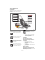
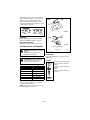
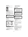
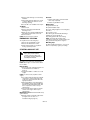
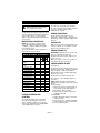
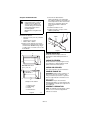
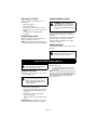
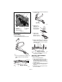
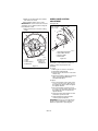
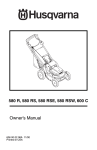
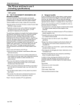
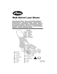
Walk Behind Lawn Mower
Owner/Operator Manual
Models
911530 - Pro 21 SCH
ENGLISH
FRANÇAIS
ESPAÑOL
Transfer
model &
serial number
label from
product
registration
here.
Coller l’autocollant du
modèle et du numéro de
série dans cet encadré.
Transferir aquí la etiqueta
del modelo y número de
serie del registro del
producto.
01239100A 3/03
Supercedes 01239100
Printed in USA
MODEL DECLARATION OF CONFORMITY ISSUED BY THE
MANUFACTURER
CERTIFICAT DE CONFORMITÉ DU MODÈLE DÉLIVRÉ PAR
LE FABRICANT
VOM HERSTELLER AUSGESTELLTE MODELLÜBEREINSTIMMUNGSERKLÄRUNG
MODELCERTIFICAAT VAN OVEREENSTEMMING
AFGEGEVEN DOOR DE FABRIKANT
DICHIARAZIONE DI CONFORMITÀ DEL PRODOTTO REALIZZATA DAL PRODUTTORE
MODELO DE DECLARACIÓN DE CONFORMIDAD EMITIDA POR EL FABRICANTE
MODEL KONFORMITETSERKLÆRING UDSTEDT AF FABRIKANTEN
MODELLENS SAMSVARSERKLÆRING UTFERDIGET AV PRODUSENTEN
FÖRSÄKRAN OM MODELLÖVERENSSTÄMMELSE, UTFÄRDAT AV TILLVERKAREN
Ariens Company
655 West Ryan Street
P.O. Box 157
Brillion, Wisconsin 54110-0157
USA
Telephone (920) 756-2141
Facsimile (920) 756-2407
We the undersigned, - Je soussigné, - Mit meiner Unterschrift - Wij de ondergetekenden, - Il sottoscritto, - El abajo
firmante - Undertegnede, - Undertecknaren av detta dokument, - Me, allekirjoittaneet,
ARIENS COMPANY, declare that the Lawn Mower- certifie que la tondeuse à gazon - erklärt, dass der
Rasenmäher - verklaart dat de maaitrekker - dichiara che il tosaerba - certifica que el cortacésped - erklærer,
at græsslåmaskinen - erklærer at plenklipperen - intygar att gräsklipparen:
Category:
Make and Trade Name:
Model:
Serial #Range:
Cutting Width (cm):
WALK BEHIND LAWN MOWER
GRAVELY
911530
000101 & up
52.1
conform to the specifications of directive 2000/14/EC, 98/37/EC, 89/336/EEC and their current amendments.
est conforme aux spécifications des directives 2000/14/CE, 98/37/CE et 89/336/CEE et à leurs modifications
actuelles.
den Spezifikationen der Richtlinie 2000/14/EC, 98/37/EC, 89/336/EEC und deren aktuellen Zusätzen entspricht.
voldoet aan de specificaties van richtlijn 2000/14/EG, 98/37/EG, 89/336/EEG en recente aanvullingen hierop.
è conforme alle specifiche contenute nelle direttive 2000/14/EC, 98/37/EC, 89/336/EEC e nei loro relativi
amendamenti.
cumple las especificaciones de la normativa 2000/14/EC, 98/37/EC, 89/336/EEC y sus enmiendas en curso.
opfylder specifikationerne i Direktiv 2000/14/EF, 98/37/EF, 89/336/EØF og gældende ændringer.
er i overensstemmelse med spesifikasjonene i direktiv 2000/14/EF, 98/37/EF, 89/336/EØF og de gjeldende
endringer.
överensstämmer med specifikationerna i direktiven 2000/14/EC, 98/37/EC, 89/336/EEC och deras nuvarande
tillägg.
Representative Measured Sound
Power Level
Niveau de puissance acoustique
représentatif
Repräsentativer gemessener
Geräuschpegel
Typisch gemeten
geluidssterkteniveau
Livello di potenza sonora
rappresentativo rilevato
Nivel de potencia acústica
representativo medido
Repræsentativt målt
lydstyrkeniveau
Representativt målt lydeffektnivå
Representativ uppmätt ljudnivå
Guaranteed Sound Power
Level
Niveau garanti de
puissance acoustique
Garantierter Geräuschpegel
Gegarandeerd
geluidssterkteniveau
Livello di potenza sonora
garantito
Nivel de potencia acústica
garantizado
Garanteret lydstyrkeniveau
Garantert lydeffektnivå
Garanterad ljudnivå
98 dBA
2
100 dBA
Stated Sound Power Levels are established following Annex VIII “Full Quality Assurance” of directive 2000/14/EC.
Les déclarations de niveau de puissance acoustique sont établies conformément à l’Article VIII « Assurance qualité
totale » de la directive 2000/14/CE.
Die angegebenen Geräuschpegel wurden gemäß Anhang VIII „Totales Qualitäts-Management“ der EU-Richtlinie
2000/14/EC.
Gespecificeerde geluidssterkteniveaus zijn vastgesteld aan de hand van Annex VIII “Full Quality Assurance”
(Volledige kwaliteitsborging) van richtlijn 2000/14/EG.
I livelli di potenza sonora dichiarati sono rilevati in base all’Appendice VIII del “Controllo qualità totale” della direttiva
CE/2000/14.
Los niveles de potencia acústica se establecen siguiendo el Anexo VIII “Garantía de calidad total” de la directiva
2000/14/EC.
De anførte lydstyrkeniveauer er fastlagte efter tillæg VIII “Fuld kvalitets sikring” i direktiv 2000/14/EF.
Lydeffektnivåene er fastsatt etter tillegg VIII ”Full kvalitetssikring” i direktivet 2000/14/EF.
Fastställda ljudnivåer har etablerats enligt bilaga VIII “Full kvalitetssäkring” i direktiv 2000/14/EC.
Notified Body –
Entité notifiée – Benachrichtigte
Körperschaft – Certificeringsinstantie
–Organismo notificato – Cuerpo
notificado – Bekendtgjort til –
Kunngjøring til – Underrättad
myndighet –
SNCH/TUV Rheinland
11, Route de Luxembourg
L-5230 Sandweiler
b
Keeper of Technical FileDépositaire du fichier technique - Verwalter der
technischen Dokumente - Houder technische
gegevens - Depositario del file tecnico Depositario del archivo técnico - Ansvarlig for
teknisk data - Ansvarlig for teknisk
dokumentasjon - Innehavare of teknisk fil -
Signature/
Unterschrift/
Handtekening
/Firma/
Underskrift/
Underskrift
Handlekening
/Underskrift/
Allekirjoitus
Barry Adamski
Product Team Leader
Chef d’équipe de produit - Produktteam-Leiter Teamleider Product - Capo team produttivo - Jefe del
equipo del producto - Produktansvarlig - Produktansvarlig
- Produktledare
Ariens Company
Gerald Johnson
Manager of Product Conformance/Position/Qualité/Functie/Qualifica/
Puesto/Stilling/Titel/Arvo
Ariens Company
9/24/02
Date/Datum/
Data/Fecha/
Dato/Päiväys
WARNING
The engine exhaust from this product
contains chemicals known to the State
of California to cause cancer, birth
defects or other reproductive harm.
3
CONTROLS AND FEATURES
1
2
9
8
3
4
7
6
5
10
1
5
10
11
12
13
13
5
16
18
19
6
15
4
17
6
14
Figure 1
ENGLISH
1. Engine/Blade Control
2. Throttle Control
3. Rear Door
4. Oil Fill/Dipstick
5. Cutting Height Levers
(2 Rear Wheel Adjusters,
2 Front Wheel Adjusters)
6. Tires
7. Fuel Tank and Cap
8. Recoil Starter Handle
9. Speed Control Rod
10. Adjustable and Folding
Handlebars
11. Wheel Drive Control
12. Grass Bag
13. Handlebar Adjustment
Holes
14. Oil Filter
15. Muffler and Muffler Guard
16. Primer
17. Side Discharge Deflector
18. Side Discharge Cover
19. Mulch Plug
FRANÇAIS
1. Commande moteur/lame
2. Commande des gaz
3. Trappe arrière
4. Tube de remplissage en
huile et jauge
5. Leviers de hauteur de
coupe (réglage par
les roues)
6. Pneus
7. Réservoir de carburant et
bouchon
8. Poignée du démarreur
manuel
9. Tige de command de
vitesse
10. Guidon réglable et pliable
11. Commande de
l’entraînement des roues
12. Sac à herbe
13. Trous de réglage du
guidon
14. Filtre à huile
15. Silencieux et Garant du
silencieux
16. Poire d’amorçage
17. Déflecteur latéral
d’évacuation
18. Plaque d’évacuation
latérale
19. Déflecteur à paillis Mulch
4
ESPAÑOL
1. Control del motor/cuchilla
2. Control del acelerado
3. Puerta trasera
4. Llenado de aceite y
varilla medidora
5. Palancas de la altura de
corte (ajustadores de la
rueda)
6. Neumáticos
7. Tapa y depósito de
combustible
8. Manilla de arranque de
retroceso
9. Varilla de control de
velocidad
10. Manillares ajustables y
plegables
11. Control de la transmisión
de la rueda
12. Bolsa de recolección del
césped
13. Agujeros para el ajuste
del manillar
14. Filtro del aceite
15. Silenciador y Protector
del silenciador
16. Cebador
17. Deflector de la descarga
lateral
18. Cubierta de la descarga
lateral
19. Tapón Mulch
TABLE OF CONTENTS
Controls and Features . . . . . . . . . . . . . 4
Safety . . . . . . . . . . . . . . . . . . . . . . . . . . . 6
Assembly . . . . . . . . . . . . . . . . . . . . . . . 10
Operation . . . . . . . . . . . . . . . . . . . . . . . 10
Maintenance . . . . . . . . . . . . . . . . . . . . 14
Service and Adjustments . . . . . . . . . . 16
Storage . . . . . . . . . . . . . . . . . . . . . . . . .
Troubleshooting . . . . . . . . . . . . . . . . .
Service Parts . . . . . . . . . . . . . . . . . . . .
Accessories . . . . . . . . . . . . . . . . . . . . .
Specifications . . . . . . . . . . . . . . . . . . .
Warranty . . . . . . . . . . . . . . . . . . . . . . . .
19
19
20
20
21
22
INTRODUCTION
THE MANUAL
PRODUCT REGISTRATION
Before using the unit, carefully and completely
read your manuals. The contents will give you
an understanding of safety instructions and
controls during normal operation and
maintenance.
All reference to left, right, front, or rear are
given from the operator’s position, facing the
direction of forward travel.
The Gravely dealer must register the product
at the time of purchase. Registering the
product will help the company process
warranty claims or contact you with the latest
service information. All claims meeting
requirements during the limited warranty
period will be honored, whether or not the
product registration card is returned. Keep a
proof of purchase if you do not register your
unit.
Customer Note: If the Dealer does not
register your product, please fill out, sign and
return the product registration card to Gravely.
SERVICE AND REPLACEMENT
PARTS
When ordering replacement parts or making
service inquiries, know the Model and Serial
numbers of your unit and engine.
Numbers are located on the product
registration form in the unit literature package.
They are also printed on a serial number label,
located on the frame of your unit (Figure 2).
Serial Number
Label
UNAUTHORIZED REPLACEMENT
PARTS
Use only Gravely replacement parts.
Replacing any part on this vehicle with
anything other than a Gravely authorized
replacement part may adversely affect the
performance, durability, or safety of this unit
and may void the warranty. Gravely disclaims
liability for any claims or damages, whether
warranty, property damage, personal injury or
death arising out of the use of unauthorized
replacement parts. To locate your nearest
Gravely Dealer, call 1-800-472-8359 or go to
www.gravely.com on the internet.
DEALER DELIVERY
Figure 2
OM1600
• Record Unit Model and Serial numbers here
• Record Engine Model & Serial numbers here
Dealer should:
1. Check that all assembly and adjustments
have been properly completed.
2. Fill out Original Purchaser Registration
Card and return the card to Gravely.
3. Explain Gravely Limited Warranty Policy.
4. Explain recommended lubrication and
maintenance. Advise customer on
adjustments. Remind customer to
change oil in 4 cycle engine crankcase
after first five (5) hours of operation.
GB - 5
© Copyright 2003 Ariens Company
5. Instruct customer on controls and
operation of unit. Discuss and emphasize
the Safety Rules. Give customer
Owner/Operator, Parts, and Engine
manuals. Advise customer to thoroughly
read and understand them.
DISCLAIMER
Gravely reserves the right to discontinue,
make changes to, and add improvements
upon its products at any time without public
notice or obligation.The descriptions and
specifications contained in this manual were in
effect at printing. Equipment described within
this manual may be optional. Some
illustrations may not apply to your unit.
SAFETY
WARNING: POTENTIALLY
HAZARDOUS SITUATION! If not
avoided, COULD RESULT in death or
serious injury.
WARNING: This cutting machine
is capable of amputating hands
and feet and throwing objects.
Failure to observe the safety
instructions in the manuals and on
decals could result in serious
injury or death.
Slopes are a major factor related
to slip and fall accidents.
Operation on all slopes requires
extra caution.
Tragic accidents can occur if the
operator is not alert to the
presence of children. Never
assume that children will remain
where you last saw them.
Gasoline is extremely flammable
and the vapors are explosive,
handle with care.
Stop unit and engine and allow
moving parts to stop before
leaving operator’s position.
CAUTION: POTENTIALLY
HAZARDOUS SITUATION! If not
avoided, MAY RESULT in minor or
moderate injury. It may also be used
to alert against unsafe practices.
NOTATIONS
NOTE: General reference information for
proper operation and maintenance practices.
IMPORTANT: Specific procedures or
information required to prevent damage to unit
or attachment.
PRACTICES AND LAWS
SAFETY ALERTS
Look for these symbols to point out
important safety precautions. They
mean:
Attention!
Personal Safety Is Involved!
Become Alert!
Obey The Message!
Practice usual and customary safe working
precautions, for the benefit of yourself and
others. Understand and follow all safety
messages. Be alert to unsafe conditions and
the possibility of minor, moderate, or serious
injury or death. Learn applicable rules and
laws in your area.
REQUIRED OPERATOR TRAINING
Original purchaser of this unit was instructed
by the seller on safe and proper operation. If
anyone other than the original purchaser will
use the unit, ALWAYS provide this manual and
any needed safety training before operation.
The safety alert symbols above and signal
words below are used on decals and in this
manual.
Read and understand all safety messages.
DANGER: IMMINENTLY
HAZARDOUS SITUATION! If not
avoided, WILL RESULT in death or
serious injury.
GB - 6
SAFETY DECALS AND
LOCATIONS
ALWAYS replace missing or damaged safety
decals. Refer to Figure 3 for safety decal
locations.
3
CAUTION
• BAG IS SUBJECT TO WEAR AND
DETERIORATION.
• CHECK BAG FEQUENTLY, REPLACE WHEN
DANGER / PELIGRO
NECESSARY.
• USE ORIGINAL BAG TO COMPLY WITH SAFETY
SPECIFICATIONS.
PRECAUCION
Y REEPLAZARLA SI ES NECESARIO.
• Read the operator's manual.
• Keep children and others away from unit while operating.
• Never direct discharge toward other people. Thrown
objects can cause injury.
• Keep safety devices (guards, shields, switches, etc.) in
place and working.
• Go across slopes, not up and down.
• Look down and behind before and while moving backward.
LAS ESPECIFICACIONES DE SEGURIDAD.
POUR EVITER LES BLESSURES GRAVES OU LA MORT
• LA BOLSA ESTA SUJETA A DESGASTE Y
DETERIORO.
• REVISAR LA BOLSA FREQUENTAMENTE,
• USAR BOLSAS ORIGINAL PARA CUMPLIR CON
REMPLACER AU BESOIN.
• Lire le manuel de l'utilisation.
• Éloigner les enfants et toute autre personne pendant le
fonctionnement de la machine.
• Ne jamais décharger directement en direction de quelqu’un.
Des particules projetées peuvent provoquer des blessures.
• Maintenir les dispositifs de sécurité (garants, protections,
commandes, etc.) en place et en bon état de
fonctionnement.
• Se déplacer en travers d’une pente et non pas de haut en
bas ou de bas en haut.
• Regarder derriere et sur les côtés lors d’une marche arrière.
AUX NORME DE SECURITE.
PARA EVITAR DAÑOS SERIOS O LA MUERTE
ATTENTION
• LE SAC EST SOUMIS À L’USURE ET A LÀ
DÉTÉRIORATION.
• VÉRIFIER LE SAC FRÉQUEMMENT. LE
• UTILISER UN BAC D’ORIGINE CONFORME
2
1
TO AVOID SERIOUS INJURY OR DEATH
• Leer el manual del operador.
• Mantener a los niños y a la gente en general alejada de la
unidad durante su operación.
• Nunca dirija la descarga hacia otras personas, a que los
objetos lanzados pueden provocar lesiones.
• Mantener los dispositivos de seguridad (guardas,
protectores, interruptores, etc.) en su lugar y en buen
estado de funcionamiento.
• En las pendientes, desplazarse transversalmente y no hacia
arriba y hacia abajo.
• Mirar siempre hacia abajo y dentrás antes de dar marcha
atrás.
07742400C
Do not operate mower
unless guards are in
operating position or
bagger is attached.
DANGER
ANGER
KEEP HANDS and FEET AWAY
08
08
83
00
MEETS C.P.S.C. BLADE
SAFETY REQUIREMENTS
Figure 3
OM1710
1. DANGER!
Keep safety devices (guards,
shields, switches, etc.) in place
and working.
TO AVOID SERIOUS INJURY OR DEATH
Read the operator’s manual.
OL3030
•
Go across slopes, not up and down.
•
Look down and behind before and
while moving backward.
OL1801
Keep children and others away
from unit while operating.
2. DANGER!
OL4370
Never direct discharge toward
other people. Thrown objects can
cause injury.
KEEP HANDS AND FEET AWAY
Do not operate mower unless guards are in
operating position or bagger is attached.
3. CAUTION!
•
OL0910
•
Do not operate mower unless
guards are in operating position
or entire bagger is attached.
OL4540
•
Bag is subject to wear and
deterioration.
Check bag frequently, replace when
necessary.
Use original bag to comply with safety
specifications.
SAFETY RULES
If unit is to be used by someone other than
original purchaser; loaned, rented or sold,
ALWAYS provide this manual and any needed
safety training before operation.
GB - 7
Read, understand and follow all safety
practices in Owner/Operator Manual before
beginning assembly. Failure to follow
instructions could result in personal injury
and/or damage to unit.
ALWAYS disconnect wire from spark plug
before assembly. Unintentional engine start up
can cause death or serious injury.
Complete a walk around inspection of unit and
work area to understand:
• work area
• your unit
• all safety decals.
Clear work area of stones, sticks, wire and
foreign objects which might be picked up and
thrown. Tall grass can hide obstacles.
Know the work area. Stay alert for holes,
rocks, rough terrain and hidden hazards.
Keep away from drop-offs, ditches, or
embankments that could cause operator to
lose footing or control of unit.
ALWAYS be aware of traffic when operating
along streets or curbs.
Keep work area clear of all persons, children
and pets.
Keep children out of the work area and under
the watchful care of a responsible adult.
ALWAYS operate unit when there is good
visibility and light.
DO NOT mow wet grass.
ALWAYS be sure of your footing. Keep a firm
hold on handlebar. Walk, NEVER run.
Engine/blade control feature on mower stops
engine and blade within 3 seconds whenever
operator releases handlebar. Check this
feature frequently. If feature fails to operate,
disconnect spark plug wire and adjust or have
it repaired before using unit.
Only trained adults may operate unit. Training
includes actual operation.
NEVER operate after or during the use of
medication, drugs or alcohol. Unit requires
complete and unimpaired attention.
NEVER allow children to use mower.
ALWAYS keep hands and feet away from
rotating parts. Rotating parts can cut off body
parts.
ALWAYS keep hands away from pinch points.
Fumes from engine exhaust can cause death
or serious injury. DO NOT run engine in an
enclosed area.
ALWAYS protect eyes, face, and body with
adequate safety gear and protective clothes.
Wear sturdy footwear, gloves and safety
goggles or safety glasses with side shields
while operating mower.
NEVER operate mower barefoot or when
wearing open sandals or canvas shoes.
NEVER wear loose clothes, long hair or
jewelry that may get caught in rotating parts.
ALWAYS stand clear of discharge when
operating unit.
NEVER direct discharge toward bystanders.
Operator is responsible for bystander safety.
DO NOT touch hot parts. Allow parts to cool.
Keep safety devices or guards in place and
functioning properly. NEVER modify or
remove safety devices.
Read, understand, and follow all instructions
in the manual and on the machine before
starting. Understand:
• How to operate all controls
• The functions of all controls
• How to STOP in an emergency.
DO NOT attempt to start your engine until you
know what the controls do and how they work.
DO NOT tilt mower when starting it.
Keep feet away when starting engine.
DO NOT start the engine or operate mower
without side discharge cover or side discharge
deflector installed.
Take all possible precautions when leaving
unit unattended.
ALWAYS shut off engine and disconnect spark
plug wire to prevent accidental starting or
unauthorized use.
Stop engine if anyone enters the work area.
NEVER attempt to make any adjustments to
unit while engine is running (except where
specifically recommended). Stop engine and
wait for all moving parts to stop before
servicing.
DO NOT make cutting height wheel
adjustments while the engine is running.
If you strike an object, or if equipment vibrates
abnormally, stop engine at once, wait for
moving parts to stop and disconnect wire from
spark plug. Repair any damage before
restarting unit.
Keep rear door closed when engine is running
unless the grass bag is in place.
Stop engine before removing and emptying
grass bag.
When mulching or bagging, ALWAYS install
discharge cover.
GB - 8
When side discharging, ALWAYS install side
discharge deflector.
ALWAYS shut off engine, allow blade to stop
and disconnect spark plug wire before clearing
clogs or cleaning unit.
Check grass bag for wear, damage, and/or
deterioration. Replace only with Gravely
original equipment replacement parts for
safety.
To reduce fire hazard and overheating, keep
equipment free of grass, leaves, debris or
excessive lubricants.
Use extra care when approaching blind
corners, shrubs, trees, or other objects which
may obscure vision.
DO NOT mow at too fast a rate. DO NOT
change engine governor setting or over-speed
the engine.
Do not operate mower on gravel or loose
material such as sand. Stop mower when
crossing drives, walks, or roads to prevent
damage or injury from thrown objects.
DO NOT pull mower backwards unless
absolutely necessary. Look down and back,
especially for small children, before and while
moving backwards.
Releasing wheel drive control must stop
mower’s forward movement. If this feature fails
to operate, disconnect spark plug wire and
repair before using unit.
Wheel drive must be disengaged when
starting engine.
DO NOT operate on steep slopes.
NEVER leave unit unattended on a slope.
Chock wheels if parking on a slope.
Mow across the face of slopes, never up and
down. Be especially cautious when changing
direction on slopes.
This product is equipped with an internal
combustion engine. DO NOT use on or near
any unimproved, forest or brush covered land
unless the exhaust system is equipped with a
spark arrestor meeting applicable local, state
or federal laws. A spark arrestor, if used, must
be maintained in effective working order by the
operator. See your Gravely Dealer or engine
manufacturer’s service center.
Fuel is highly flammable and its vapors can
explode. ONLY use approved fuel containers.
• NO Smoking!
• NO Sparks!
• NO Flames!
• Allow engine to cool before filling fuel
tank.
Never fill containers inside a vehicle or on a
truck or trailer bed with a plastic liner. Always
place containers on the ground away from
your vehicle before filling.
When practical, remove gas-powered
equipment from the truck or trailer and refuel it
on the ground. If this is not possible, then
refuel such equipment on a trailer with a
portable container, rather than from a gasoline
dispenser nozzle.
Keep the nozzle in contact with the rim of the
fuel tank or container opening at all times until
fueling is complete. Do not use a nozzle lockopen device.
Check fuel supply before starting engine.
DO NOT fill gasoline tank indoors, when
engine is running, or while engine is hot.
Allow engine to cool several minutes before
removing fuel cap.
DO NOT overfill. Allow about 1/4" (6 mm) of
tank space for fuel expansion.
Replace gasoline tank cap securely and clean
any spilled fuel before starting engine.
If fuel is spilled on clothing, change clothing
immediately.
NEVER store fuel inside where there is an
open flame, such as a water heater.
ALWAYS drain fuel outdoors away from
ignition sources.
Avoid Electric Shock. DO NOT disconnect wire
from spark plug while engine is running.
Accidental engine start up can cause death or
serious injury. Except where specifically
recommended, ALWAYS stop engine, wait for
moving parts to stop, allow parts to cool and
disconnect spark plug wire before inspecting,
servicing, adjusting or repairing unit.
Keep mower free of grass, leaves, or other
debris build-up.
Keep equipment in good condition.
Maintain or replace safety and instruction
labels, as necessary.
Follow engine manufacturer’s safety
instruction when servicing engine.
Check all hardware at regular intervals,
especially blade attachment bolts. Keep all
hardware properly tightened.
Before tipping unit, remove fuel.
Ensure all wheel blocks, jack stands and tie
downs will support unit during maintenance.
Replace worn-out mufflers immediately.
Continued use could result in fire or explosion.
Sharp edges can cut or amputate fingers or a
hand. Wrap blade or wear sturdy gloves to
service.
GB - 9
Use only replacement parts designed for your
unit. See your Gravely Dealer.
Allow engine to cool before storing in any
enclosure.
ALWAYS clean unit before extended storage.
See engine manual for proper storage.
DO NOT store unit inside a building with fuel in
the fuel tank where any ignition sources are
present.
Use only accessories which have been
approved by Gravely and are properly
installed.
Check attachments frequently and replace
worn or damaged components with
manufacturer’s recommended parts.
ASSEMBLY
ASSEMBLY
CAUTION: AVOID INJURY. Read
and understand the entire Safety
section before proceeding.
CARTON CONTENTS
1
6
2
3
5
4
1.
2.
3.
4.
5.
6.
OM1620
Mower Unit
Side Discharge Deflector
Mulch Plug
Literature Pack
Grass Bag
Grass Bag Frame
1. Unfold and adjust handlebar. See
Handlebar Height on page 16.
NOTE: DO NOT bend the speed control rod (if
equipped) when unfolding the handlebars.
2. Fill engine crankcase with oil. See engine
manual.
3. Assemble grass bag onto bag frame.
4. Set-up mower for bagging, side
discharge or mulching. See Mower SetUp on page 12.
5. Fill fuel tank. See Filling Fuel Tank on
page 12.
6. Connect spark plug wire.
7. Check the engine/blade control feature.
Try starting the engine without the
engine/blade control held against the
handlebar. Engine must not start. If
engine starts, stop engine and adjust or
repair engine/blade control. See
Engine/Blade Control Adjustment on
page 17.
Figure 4
OPERATION
CONTROLS AND FEATURES
Engine/Blade Control
See Figure 1 for locations.
WARNING: Improper operation can
lead to injury. Learn what the
controls do and how they work.
Thoroughly read and understand
entire Operator Manual.
CAUTION: Check function of
Engine/Blade Control regularly.
Improper function of control could
cause injury.
The engine/blade control must be held against
the handlebar to start the engine and blade.
CAUTION: AVOID INJURY. Read
and understand the entire Safety
section before proceeding.
GB - 10
Engine/blade control feature on mower stops
engine and blade within 3 seconds whenever
operator releases handlebar. Check this
feature frequently. If feature fails to operate,
disconnect spark plug wire and adjust or have
it repaired before using unit.
High
Low
1
Rear
STOP
START and RUN
1
OM1230
Handlebar
Low
Adjust handlebar to a safe and comfortable
height. See Handlebar Height on page 16.
High
Recoil Starter Handle
When pulled, handle will turn engine over.
Front
CUTTING HEIGHT ADJUSTMENT
1. Cutting Height Lever
Figure 5
DANGER: Avoid injury from rotating
blade.
ALWAYS shut off engine before
adjusting cutting height.
CONTROLS
Primer Bulb
Push the primer bulb in to add fuel for easier
engine start.
CAUTION: Both rear wheels must
be set at same height or traction
drive may not work properly.
Throttle
1
Cutting Height Settings Chart
Notch
LOW
2
3
4
5
HIGH
OM0165
Cut grass length
1" (25 mm)
1-3/8" (35 mm)
1-3/4" (45 mm)
2-1/4" (57 mm)
2-3/4" (70 mm)
3-1/4" (83 mm)
2
3
OL2074
To change cutting height, move cutting height
levers one notch at a time on each wheel to
set desired height (Figure 5).
NOTE: Each wheel on mower must be set at
the same height for a level cut.
GB - 11
The throttle controls the engine
speed and chokes engine for
starting.
1.Start - Push lever all the way
forward.
2.Fast.
3.Slow - Pull lever all the way
rearward.
Speed Control
5. Fill fuel tank. (see Specifications on
page 21 for tank capacity.)
6. Replace fuel cap and tighten.
7. ALWAYS clean any spilled fuel.
Speed control rod changes the mower’s
forward travel speeds.
MOWER SET-UP
High –Push rod all the way
forward.
CAUTION: DO NOT operate
mower unless either side discharge
cover or side discharge deflector is
installed. Thrown objects may
cause damage or injury. Never
operate unit with rear door open
unless grass bag is in place.
Low –Pull rod all the way
rearward.
Start mowing slowly and use speed control
rod to gradually increase speed to a safe,
comfortable walking pace.
Speed control rod should hold the desired
speed. If not, adjust speed control bell crank.
(See Speed Control Bell Crank on page 19.)
OM0480
CAUTION: If clog or obstruction
prevents grass flow, release
engine/blade control and disconnect
spark plug wire before attempting to
clear away any clogs.
Wheel Drive Control
CAUTION: Unit will move forward at
engine start if wheel drive control is
engaged. ALWAYS release wheel
drive control before starting unit.
NOTE: Engine must be running for wheel drive
to propel unit.
To drive forward:
Slowly squeeze and hold wheel drive control
against handlebar.
To stop:
Release wheel drive control.
To Bag
CAUTION: Check grass bag
frequently for wear or deterioration.
Replace worn or damaged bag with
Gravely original equipment
replacement bag only.
1. Shut off unit.
2. Install side discharge cover.
3. Lift rear door.
4. Hook grass bag frame on mounting
flange.
5. Lower rear door.
If necessary, lift rear of grass bag frame to lock
in position.
There should be no openings between bag
and mounting surface after installing bag. If
necessary, clear debris from bag mounting
surface.
Grass Bag Removal
STOP
GO
OM1240
FILLING FUEL TANK
To add fuel to fuel tank:
1. Put unit in open or well-ventilated area.
2. Stop engine and allow to cool.
3. Clean fuel cap and surrounding area.
4. Remove cap.
IMPORTANT: See engine manual for correct
type and grade of fuel.
1. Shut off unit.
2. Lift rear door.
3. Use handle to lift bag off mounting flange.
4. Close rear door.
NOTE: Empty grass bag and clean mower pan
after each use. DO NOT allow grass clumps or
a grass coating to collect inside of grass bag
or mower pan. Remove grass bag from
mower, wash bag with hose and allow to dry.
To Side Discharge
GB - 12
1. Shut off unit.
2. Install Mulchmaster plug (see below).
3. Remove grass bag.
4. Remove side discharge cover and keep
hardware.
5. Attach side discharge deflector to studs
on mower. Make sure deflector covers
discharge opening.
6. Secure with cover hardware from step 4.
To Mulch
1. Shut off unit.
2. Remove grass bag and install side
discharge cover.
3. Open rear door and insert Mulchmaster
plug with the beveled face to the left.
4. Close rear door.
NOTE: Rear door must close flush.
EMERGENCY STOPPING
To stop the mower in an emergency:
1. Release the engine/blade control.
2. Release the wheel drive control.
3. Allow all moving parts to stop before
leaving operator’s position.
Shut Off
1. Release wheel drive control and allow
unit to stop completely.
2. Release engine/blade control.
Mowing Tips
Cut grass when it is dry.
Keep mower blades sharp.
Do not set cutting height too low. For tall grass,
mow twice.
Do not mow too fast.
Mow with engine at full throttle. Discharge
clippings into areas already cut.
Vary cutting pattern with each mowing.
NOTE: To prevent dirt and grass from
collecting on mower pan, avoid operating over
bare ground with only patches of grass.
Mulching Tips
For best mulching performance, cut no more
than 1 inch (2.54 cm) of grass per cutting.
STARTING AND SHUT OFF
WARNING: Improper operation can
lead to injury. Learn what the
controls do and how they work.
Thoroughly read and understand
entire Operator Manual.
See Figure 1 for all Controls and Features.
NOTE: Start engine on a level surface that is
free of debris.
Manual Start
1. Check each item under Before Each Use
in the Maintenance Schedule on
page 14.
2. Push primer bulb 2 or 3 times for a cold
engine.
NOTE: It is unnecessary to prime a warm
engine.
3. For engines with a throttle, place throttle
control in the choke position. Once the
engine has started, place throttle in the
high speed detent.
4. With engine/blade control held against
the handlebar, grasp starter handle and
pull rope slowly until it pulls harder. This
is the compression stroke. Let rope
rewind slowly.
5. Pull rope with rapid continuous full arm
stroke to start engine. Allow rope to
rewind slowly.
IMPORTANT: DO NOT let starter handle snap
against bracket.
6. Repeat steps 4 and 5 until engine starts.
(If engine does not start, see
Troubleshooting on page 19.)
GB - 13
MAINTENANCE
CHECK WHEEL DRIVE CONTROL
CAUTION: AVOID INJURY. Read
and understand the entire Safety
section before proceeding.
Gravely Dealers will provide any service, parts
or adjustments which may be required to keep
your unit operating at peak efficiency. Should
engine require service, contact a Gravely
dealer or an authorized engine manufacturer's
service center.
MAINTENANCE SCHEDULE
Check Engine/Blade
Control
Check Wheel Drive
Control
Check Grass Bag
Clean Unit
Check Engine Oil
Check Mower Blade
Check Drive Belt
Check Fasteners
Check Air Cleaner
Change Engine Oil
General Lubrication
Replace Oil Filter
Check Spark Plug
Check Engine
Cooling
Check Muffler
*
25
Check grass bag frequently for wear or
deterioration. Replace worn or damaged bag
with Gravely original equipment replacement
bag only.
Before each use clean unit, muffler and engine
surfaces of debris, oil or fuel spills to ensure
proper cooling and prevent fires.
CHECK ENGINE OIL
MAINTENANCE SCHEDULE
Before
Each
Use
•
CHECK GRASS BAG
CLEAN UNIT
NOTE: Some working conditions (heavy
loads, high ambient temperatures, dusty
conditions, or airborne debris) may require
more frequent service.
See engine manual for further maintenance
and troubleshooting information.
Service Performed
The unit must stop quickly and completely
when the control is released. Adjust or repair if
necessary. See Wheel Drive Control
Adjustment on page 18.
100
IMPORTANT: Maintain proper oil level at all
times or engine damage will result.
Check the level of the engine crankcase oil
before each use.
Make sure engine is level when checking oil.
See engine manual for instructions.
CHECK MOWER BLADE
•
•
•
•
•
•
•
•
•
*•
•
•
•
•
After first 5 Hours of operation
CHECK ENGINE/BLADE
CONTROL
The engine and blade must stop within 3
seconds after releasing the control. If the
engine and blade continue to run, adjust or
repair control immediately. See Engine/Blade
Control Adjustment on page 17.
See Figure 6.
Check blade mounting: blade must be secure
and bolt torqued to 37.5 - 50 lbf-ft (51-68 N•m)
(bolt should fully compress lock washer).
Check blade for nicks and dull cutting edges.
Sharpen if necessary.
Check blade for rounded or broken ends,
thinned metal or other damage. Replace if
necessary.
NOTE: Blades should be sharpened and
balanced professionally. Contact your Gravely
Dealer.
To remove blade:
1. Stop engine, wait for all moving parts to
stop, and disconnect spark plug wire.
2. Block blade to prevent rotation.
3. Remove bolt, lock washer, flat washer
and blade from shaft.
To install blade:
1. Replace blade, flat washer, lock washer
and bolt on shaft.
2. Torque bolt to 37.5 - 50 lbf-ft (51-68 N•m)
(bolt should fully compress lock washer).
3. Connect spark plug wire.
GB - 14
Sharpen the Mower Blades
3. Check mower blade balance.
Slide mower blade on an unthreaded
bolt. A balanced blade should remain in a
horizontal position. If either end of mower
blade moves downward, sharpen the
heavy end until blade is balanced
(Figure 7).
4. Install mower blade on unit.
5. Tighten the bolts to a torque of 37.5 50 lbf-ft (51-68 N•m).
CAUTION: DO NOT sharpen
mower blades while on unit. An
unbalanced mower blade will
cause excessive vibration and
eventual damage to unit. Check
mower blade balance before
reinstalling blades.
NEVER weld or straighten bent
blades.
1. Remove mower blade from unit.
Discard mower blade if:
• More than 1/2 in. (1.27 cm) of metal is
removed.
• Air lifts become eroded.
• Blade is bent or broken.
2. Sharpen mower blade by removing an
equal amount of material from each end
of mower blade. DO NOT change angle
of cutting edge or round the corner of the
mower blade.
Blade
Bolt
Figure 7
DO NOT Sharpen to This Pattern
CHECK DRIVE BELT
2
1
OA0013
Check drive belt and replace if worn or
damaged. See Drive Belt Replacement on
page 17.
CHECK FASTENERS
3
Check all fasteners for proper tightness. Pay
special attention to blade hardware and all
guards, shields and safety devices.
DISCARD if More Than
1/2 in. (1.27 cm)
CHECK AIR CLEANER
2
See engine manual for specific information.
CHANGE ENGINE OIL
4
IMPORTANT: Change engine crankcase oil
after first five (5) hours of operation. Then
change oil after every 25 hours of operation.
Refer to engine manual for instructions and
proper oil type.
IMPORTANT: Proper oil level must be
maintained at all times or engine damage will
result. DO NOT overfill. Be sure engine is level
when adding oil.
3
Sharpen to This Pattern
1.
2.
3.
4.
Square Corner
Cutting Edge
Air Lift
Air Lift Erosion
Figure 6
GENERAL LUBRICATION
NOTE: The LM21SC has lube fittings on drive
mount for use in commercial applications.
Lubricate as needed.
OT0792
GB - 15
REPLACE OIL FILTER
CHECK ENGINE COOLING
Replace oil filter every 100 hours of use or
every season.
1. Change engine oil.
2. Clean around filter.
3. Turn filter counterclockwise to remove.
4. Apply a thin coat of oil onto seal of new
filter.
5. Install new filter and hand tighten
securely.
WARNING: HOT SURFACES can
cause death or serious injury. DO
NOT TOUCH parts which are hot
from operation. ALWAYS allow parts
to cool.
CHECK SPARK PLUG
Spark plug should be replaced every 100
hours of operation or each year.
NOTE: Loose spark plug wire terminals can
cause sparking. Replace terminal if damaged.
To prevent overheating, air must circulate
freely around the cooling fins, cylinder head
and block.
Every 100 hours of operation or yearly (more
often if conditions require) remove blower
housing and clean cooling fins. See engine
manual for instructions.
CHECK MUFFLER
Check muffler for debris, cracks, wear, or other
damage.
CAUTION: Replace worn-out
mufflers immediately. Continued use
could result in fire or explosion.
SERVICE AND ADJUSTMENTS
HANDLEBAR HEIGHT
CAUTION: AVOID INJURY. Read
and understand the entire Safety
section before proceeding.
SERVICE POSITION
Put unit into service position for easy access
to underneath the deck.
CAUTION: Avoid fuel spills. Follow
steps below to help prevent fuel
spills. If fuel leaks into air cleaner,
replace air cleaner. ALWAYS clean
up any spilled fuel.
To adjust (Figure 8):
1. Use the fasteners to attach one of the
holes at the top and one of the holes at
the bottom.
NOTE: To fold handlebars flat for storage, pull
the speed control rod (if equipped) all the way
back, disconnect braces from support bracket,
and fold handlebar forward. Do Not bend
speed control rod.
1. Place unit on a flat, level surface.
2. Disconnect spark plug wire.
3. Remove fuel cap, place a piece of plastic
bag over the opening and tighten cap
securely.
4. Tip unit onto left side, opposite the
discharge opening.
Make sure unit is secure and will not tip
over.
IMPORTANT: Remove plastic from fuel cap
after unit is upright and service is complete.
GB - 16
3. Pull cable down from bracket until there is
no slack in cable.
2
3
1
4
No slack
5
OM1061
4. Tighten lower
cable nut to 1/8"
(3 mm) below
bracket. Release
z-bend bracket.
2
4
1. Handlebar
2. Adjustment Hole
3. Support Bracket
OM1660
4. Fasteners
5. Brace
1/8
(3 m ”
m)
Figure 8
OM1020
ENGINE/BLADE CONTROL
ADJUSTMENT
5. Tighten upper
cable nut until
bracket is secure
between cable nuts.
To adjust engine/blade control:
1. Loosen cable nuts away from bracket.
OM1030
6. Engage engine/blade control. Measure
distance between middle of z-bend and
cable bracket. Measurement should be
as shown below.
1.325"-1.788"
(3.4 cm - 4.5 cm)
Briggs & Stratton
OM1051
7. If correct measurement cannot be set,
contact your local dealer.
OM1010
2. Squeeze z-bend bracket at engine end of
cable toward front of unit and hold in
place.
Briggs & Stratton
OM1040
DRIVE BELT REPLACEMENT
To remove drive belt:
1. Disconnect spark plug wire.
2. Set the right rear wheel to its lowest
cutting height, and the left rear wheel to
the third cutting height. This position
provides clearance between friction disc
and drive sheave.
3. Remove belt from the idler, then the drive
sheave, and finally, the engine pulley
(Figure 9).
4. Pull belt through opening under mower
pan and over blade.
GB - 17
5. Make sure the idler pulley turns and the
idler arm moves freely.
6. Reinstall drive belt in reverse order.
IMPORTANT: Be sure the belt seats in sheave
and pulley grooves with the idler touching the
back (flat) side of belt.
7. Adjust rear wheels to the same cutting
height.
WHEEL DRIVE CONTROL
ADJUSTMENT
See Figure 10.
2-1/4" to 2-3/4"
(5.7 to 7 cm)
2
1
6
5
1
4
3
2
OM0294
1.
2.
3.
4.
4
3
Handlebar Indentation
Wheel Drive Control
Traction Cable
Cable Nuts
OM1250
1.
2.
3.
4.
Blade
Idler
Drive Sheave
Drive Belt
5. Engine Pulley
6. Bolt, Lock
Washer &
Flat Washer
Figure 9
Figure 10
The wheel drive must start to engage when
wheel drive control is between 2-1/4" and
2-3/4" (5.7 and 7 cm) away from the
handlebar.
To check:
1. With engine off, select a slow speed.
2. Slowly pull unit backwards.
3. Slowly squeeze wheel drive control until
wheels stop.
4. Measure the distance between the wheel
drive control and handlebar at the
handlebar indentation.
To adjust:
1. If the measurement is more than 2-3/4"
(7 cm), loosen the lower cable nut and
then tighten the upper cable nut against
the adjuster bracket.
2. If the measurement is less than 2-1/4"
(5.7 cm), loosen the upper cable nut and
then tighten the lower nut against the
adjuster bracket.
3. Recheck measurement with the slowest
and fastest speeds selected.
4. Repeat adjustment until wheel drive
control is properly adjusted.
IMPORTANT: If there is not enough thread
length for proper adjustment, contact your
Dealer for repairs before operating unit.
GB - 18
SPEED CONTROL BELL CRANK
1
The speed control bell crank holds the speed
control rod in position after a speed has been
set. The spring washers may become loose
with normal wear. If the speed control rod
does not stay firmly in position, adjust the
speed control bell crank. See Figure 11.
To adjust:
1. Remove cover, fully compress the
helical spring lock washers with lock
nut and then back lock nut off, one
quarter turn.
2. If the speed control rod is still too loose,
tighten lock nut by small increments
until it holds its position. Tightening the
lock nut too much will not allow the
speed control rod to move at all.
3. Align notch in left hand side of cover
with bolt and secure with knob.
2
6
5
4
1. Lock Nut
2. Helical Spring
Lock Washers
3. Speed Control
Bell Crank
OM1670
3
4. Swivel
5. Hair Pin
6. Speed Control
Rod
Figure 11
STORAGE
Inspection
CAUTION: AVOID INJURY. Read
and understand the entire Safety
section before proceeding.
IMPORTANT: NEVER spray unit with high
pressure water or store unit outdoors. Store
mower in a cool, dry, protected location.
Inspect mower and repair or replace worn or
damaged parts to avoid delays when
beginning use again.
Regularly check all hardware and keep
fasteners tight. Know unit is in safe working
condition.
Cleaning
Grass Bag
Clean unit thoroughly with mild soap and low
pressure water. Brush off dirt and debris from
all surfaces. Touch-up all scratched surfaces
to prevent rust. Matching touch-up paint is
available from your Gravely Dealer. Do not use
abrasives, solvents, or harsh cleaners.
Wash out grass bag and allow to dry before
storage. Grass bag may be stored in position
on mower.
Engine
When storing unit for extended periods of
time, remove all fuel from tank and carburetor
(run dry). Refer to engine manual.
TROUBLESHOOTING
PROBLEM
PROBABLE CAUSE
Engine will not
start
1. Fuel tank empty or low.
Engine is
difficult to
restart
1. Mower clogged with grass.
2. Spark plug wire loose or off.
3. Engine/Blade control cable
detached, broken, or not
adjusted properly.
GB - 19
CORRECTION
1. Check fuel level. Fill tank if
necessary.
2. Check connection.
3. Check cable. Adjust, repair or
replace as necessary.
1. Clear clippings from under
mower. (Allow the mower to
clear clippings before shutting
off engine.)
PROBLEM
Cut is poor
PROBABLE CAUSE
CORRECTION
1. Worn blade.
1. Check blade (See
Maintenance).
2. Raise cutting height.
2. Too much grass is being
removed per cutting.
3. Grass is too wet.
4. Mowing speed is too fast.
3. Allow grass to dry.
4. Mow slower.
Grass does not
disperse
evenly
1. Too much grass is being
removed per cutting.
2. Grass is too wet.
3. Mowing speed is too fast.
1. Raise cutting height.
Mower does
not bag
clippings
1. Grass bag is overfilled.
1. Empty grass bag and do not
allow it to overfill.
2. Remove mulching plug.
Wheel drive
does not
engage.
1. Wheel drive control not
engaged.
2. Drive belt out of position.
2. Allow grass to dry.
3. Mow slower.
2. Mulching plug is installed.
1. Engage wheel drive control.
2. Check drive belt. Adjust as
necessary (See Service and
Adjustments).
3. Replace belt (See Service
and Adjustments).
4. Adjust rear wheels to same
cutting height (See
Operation).
5. Attach idler spring to notch on
idler arm. Contact your
Dealer.
6. Check wheel drive control
cable. Adjust or replace as
needed. See Service and
Adjustments.
7. Contact your Dealer.
3. Drive belt worn or damaged.
4. Rear wheels in different cutting
heights.
5. Idler spring detached.
6. Wheel drive control cable
detached or broken.
7. Friction disc not adjusted
properly or damaged.
8. Bearings damaged.
9. Debris in gear set.
8. Contact your Dealer.
9. Contact your Dealer.
ACCESSORIES
SERVICE PARTS
Always use genuine Gravely parts to keep
your mower running like new.
See your authorized Gravely dealer to add
these optional accessories.
Mower Model
71102400
Dethatcher
Mulchmaster Plug
911530
Air Filter
21535600
71102700
Oil Filter
08266101
71103000
Grass Bag
Spark Plug
21534100
71103200
Rear Discharge Chute
Blade
01137000 (Standard)
01182400 (Tungsten)
71103500
Mulchmaster Mulching Kit
71103700
Leaf Shredder
Drive Belt
07217100
71103900
Straight Axle Kit
Friction Disc
03240700
71104100
Front Swivel Wheel Kit
GB - 20
SPECIFICATIONS
Model Number
Description
Length - in (cm)
Height - in (cm)
Width - in (cm)
Actual Weight - lbs (kg)
Cutting Width
Cutting Height - in. (cm)
Engine, Briggs & Stratton 4 cycle
Model
Trim
Engine Power - HP (kW) @ Max.
Governed RPM
Max Rotation Speed
of Cutting Edge - RPM (min-1)
Governed RPM
Displacement Cu. In. (cc)
Cylinder Bore
Engine Oil Type
Crank Case Capacity - Oz. (Liter)
Oil System
Engine Oil Filter
Spark Plug Gap - in (mm)
Fuel Type
Fuel Tank Capacity - qt (Liter)
Primer Bulb
Throttle
Air Cleaner
Starting
Differential
Variable Speeds - MPH (km/hr)
Mower Deck
Front Wheel Dia - in (cm)
Rear Wheel Dia - in (cm)
Oper. Ear Sound Press. (Lpa) dBA
911530
PRO21SCH
61.5 (156)
38 (96.5)
23 (58.4)
110 (49.9)
21 (53.3)
6 Positions: 1.00-3.25
(2.5 - 8.3)
Intek Pro OHV
122672
0211E1
4.37 (3.26)
2900
2800 +/- 100
11.57 (190)
Cast Iron Sleeve
SAE 30
20 (0.59)
Pressurized
Spin-on
0.020 (0.51)
Unleaded
1.6 (1.5)
Standard
Standard
Paper Element
Recoil
Standard
0-4 (0-6.4)
14 Gauge - Stamped
Steel
7.5 (19.1)
10.5 (26.7)
87
VIBRATION MEASURE (m /s2) @ Operator hands
X axis
2.6
Y axis
7.7
Z axis
2.7
GB - 21
2-Year Limited Warranty
Gravely Division of Ariens Company
655 West Ryan Street
P.O. Box 157
Brillion, WI 54110-0157
920-756-2141
Fax 920-756-2407
www.gravely.com
GT and GLT Tractors, ZT Mower, PRO 21 Mower, String
Trimmer, and Gravely at Home products
Gravely Division of Ariens Company (Gravely) warrants to the original purchaser
that consumer products manufactured by Gravely will be free from defects in material
and workmanship for a period of two (2) years after the date of purchase. Gravely
will repair any defect in material or workmanship, and repair or replace any defective
part, subject to the exceptions, exclusions, conditions and limitations set forth herein.
The two-year duration of this warranty applies only if the product is put to ordinary,
reasonable, and usual personal, family, or household uses. If the product is put to
any business, commercial, or industrial use, such as, but not limited to, commercial
landscaping, mowing or snow removal services, or golf course or park maintenance,
or agricultural or farmstead use, then the duration of this warranty is ninety (90) days
after the date of purchase, or one (1) year after the date of purchase for the Pro 21
Mower. If any product is rented or leased, then the duration of this warranty is ninety
(90) days after date of purchase.
Genuine Gravely service parts and accessories not purchased with the product
covered by this warranty, but which are later purchased and used with that product,
are warranted to be free from defects in material and workmanship for a period of
ninety (90) days after date of purchase, and Gravely will repair or replace any such
part or accessory free of charge, except for labor, during that period.
This warranty is subject to the following exceptions, conditions, and limitations:
This warranty is valid only if the following conditions
are met:
• The purchaser must perform maintenance and minor
adjustments explained in the owner’s manual.
• The purchaser must promptly notify Gravely or an authorized
Gravely service representative of the need for warranty
service.
• Returning the product registration card to Gravely will
enable the company to contact the registrant with repair
or replacement part information.
This warranty is subject to the following limitations:
• The purchaser must transport the product to and from the
place of warranty repair.
• Warranty service must be performed by an authorized
Gravely service representative. (To find an authorized
Gravely service representative, contact Gravely at the
website, number or address above.)
• Batteries are warranted for a period of twelve (12) months
after date of purchase, on a prorated basis. For the first
ninety (90) days of the warranty period, a defective battery
will be replaced without charge. If the applicable warranty
period is more than ninety (90) days, Gravely will cover
the prorated cost of any defective battery, for up to twelve
(12) months after date of purchase.
The following items are not covered by this warranty:
• Engines and engine accessories are covered only by the
warranty made by the engine manufacturer, and are not
covered by this warranty.
• If the product is equipped with a Peerless gearbox and/or
transmission, the gearbox and/or transmission are covered
only by the warranty made by Peerless, and are not covered
by this warranty.
• If the product is equipped with a Hydro-Gear transmission
and/or Hydro-Gear drive components, the Hydro-Gear
transmission and/or drive components are covered only
by the warranty made by Hydro-Gear, and are not covered
by this warranty.
• Service work performed by, and parts installed by, someone
other than an authorized Gravely service representative
are not covered by this warranty.
• Parts that are not genuine Gravely service parts are not
covered by this warranty.
• Shoes, runners, scraper blades, shear bolts, mower blades,
mower vanes, trimmer line, headlights, light bulbs are not
covered by this warranty.
• Any defect which is the result of misuse, alteration, improper
assembly, improper adjustment, neglect, or accident is not
covered by this warranty.
• Products which were not purchased in the United States,
Puerto Rico, or Canada are not covered by this warranty.
In all other countries, contact place of purchase.
LIMITATION OF REMEDY AND DAMAGES
DISCLAIMER OF FURTHER WARRANTY
Gravely’s liability under this express warranty, and under any
implied warranty that may exist, is limited to repair or
replacement of any defective part. Gravely shall not be liable
for incidental, special, or consequential damages (including
lost profits). Some states do not allow the exclusion of
incidental or consequential damages, so the above limitation
or exclusion may not apply to you.
Gravely makes no warranty, express or implied,
other than what is expressly made in this
warranty. If the law of your state provides that
an implied warranty of merchantability, or an
implied warranty of fitness for particular
purpose, or any other implied warranty, applies
to Gravely, then any such implied warranty is
limited to the duration of this warranty. Some
states do not allow limitations on how long an
implied warranty lasts, so the above limitation
may not apply to you.
This warranty gives you specific legal rights, and you may also have other
rights which vary from state to state.
Form: GCLW2-122002
GB - 22
GRAVELY’
A Division of Ariens Company
655 West Ryan Street
P.O. Box 157
Brillion, WI 54110-0157
920-756-2141
Fax 920-756-2407
www.gravely.com