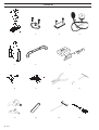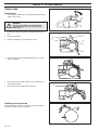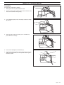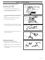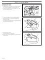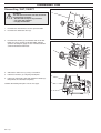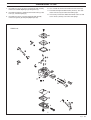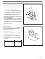
1
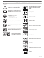
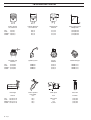
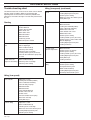
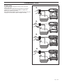
334T 338XPT
336 339XP
English
CONTENTS
Introduction .................................................... 3
Safety instructions ......................................... 4
Symbol explanation ....................................... 5
Technical Data ................................................ 6
Tools ................................................................ 8
Trouble shooting .......................................... 10
Service data 334T/338XPT ........................... 12
Service data 336/339XP ............................... 14
Safety equipment ......................................... 16
Starter............................................................ 23
Ignition system ............................................. 25
Centrifugal clutch ......................................... 27
Carburettor ................................................... 29
Tank unit ....................................................... 41
AV-System ..................................................... 46
Crankshaft, Piston and Cylinder................. 47
Bar bolt .......................................................... 51
Oil pump ........................................................ 52
2 – English
INTRODUCTION
General
Layout
This Workshop Manual provides a comprehensive description
of how to trouble shoot, repair and test the chain saw. A
description of different safety measures that should be taken
during repair work is also given.
This Workshop Manual can be used in two different ways:
Safety
Repair of a particular system
NOTE!
The section dealing with safety must be read and understood by all those carrying out repair work or service on
the chain saw.
• For the repair of a particular system on the chain saw.
• For dismantling and assembly of the entire chain saw.
When a particular system on the chain saw is to be repaired,
proceed as follows:
1.
Look up the page for the system in question.
2.
Carry out the sections:
• Dismantling
• Cleaning and Inspection
• Assembly
Warning symbols can be found in this Workshop Manual and on
the chain saw. See the chapter "Symbol explanation". A new
decal must be applied as soon as possible if a warning symbol
on the chain saw has been damaged or is missing so that the
greatest possible safety can be obtained when using the chain
saw.
Target group
When producing this Workshop Manual the assumption has
been made that personnel who use it have general knowledge
in the repair and service of small engines.
The Workshop Manual must be read and understood by
personnel who will carry out repair work and service on the
chain saw. The Manual is also suitable for use when training
new employees.
Modifications
Modifications will be successively introduced on the chain saw
during production. When these modifications affect the service
and/or spare parts, separate service information will be sent out
on each occasion. This means that in time this Workshop
manual will become out of date. In order to prevent this, the
Manual should be read together with all service information
concerning the chain saw in question.
Tools
Dismantling and assembly of the
entire chain saw
Proceed as follows when the entire chain saw is to be dismantled and assembled:
1.
Look up the chapter "Starter" which deals with the Starter
and carry out the instructions set out under Dismantling.
2.
Work forward in the Manual and carry out Dismantling in
the order set out in the sections.
3.
Go back to the chapter "Starter" and carry out the instructions under Cleaning and Inspection.
4.
Work forward in the Manual and carry out Cleaning and
Inspection in the order set out in the sections.
5.
Order or take out all requisite spare parts from the stores.
6.
Look up the chapter "Oil pump" which deals with the Oil
pump and carry out the instructions set out under Assembly.
7.
Work back towards the beginning of the Manual and carry
out Assembly in the order set out in the sections.
Some sections include a Description of the actual unit in order
to increase the basic understanding.
Special tools must be used during specific steps. All service
tools are listed in the Workshop Manual. Usage is evident from
respective sections.
Always use Husqvarna’s original:
• Spare parts
• Service tools
• Accessories
Numbering
Position references to components inside the figures are
designated A, B, etc.
The position references restart in each new section.
English –
3
SAFETY REGULATIONS
General instructions
Special instructions
The workshop where chain saw repairs are to be done must be
equipped with safety equipment as set out in local provisions.
The fuel used in the chain saw has the following hazardous
properties:
No one may repair the chain saw unless they have read and
understood the content of this Workshop Manual.
• The fluid and its vapour are poisonous.
• Can cause skin irritation.
• Is highly inflammable.
This Workshop Manual contains the following boxes in relevant
places. Warning boxes are positioned before the procedures
they refer to.
WARNING!
The warning box warns of the risk of personal
injury if the instructions are not followed.
The bar, chain and clutch cover (chain brake) must be fitted
before the saw is started otherwise the clutch can work loose
and cause personal injury.
Wear ear-muffs when test running.
Do not use the saw until it has been adjusted so that the chain
remains still when idling.
After test running, do not touch the muffler until it has cooled.
Risk for burns.
NOTE!
This box warns of material damage if the instructions are
not followed.
Insufficient chain lubrication can result in chain breakage, which
can cause serious, even life-threatening injury.
Ensure that the spring in the starter does not fly out and cause
personal injury.
If the spring tension is activated on the starter pulley when it is
to be taken up, the spring can fly out and cause personal injury.
Check that the brake is applied when removing the pressure
spring on the chain brake. Otherwise the pressure spring can fly
out and cause personal injury.
Do not direct the compressed air jet towards the body when
using compressed air. Air can penetrate in to the blood circulation, which means mortal danger.
4 – English
SYMBOL EXPLANATION
Symbols
WARNING! Chain saws can be dangerous!
Careless or incorrect usage can result in
serious injury even death to operator or
others.
Inspection and/or maintenance should be
carried out with the engine switched off,
and with the stop switch in the "STOP"
position.
Read through the Operator Guide carefully
and understand the content before using the
chain saw.
Operating mode
Always use:
• An approved safety helmet
• Approved ear-muffs
• Protective glasses or a visor
Choke, 334T, 338XPT
Always use both hands whenever possible
with all chain saw work.
Choke, 336, 339XP
Avoid contact between the tip of the bar and
objects.
Always wear approved protective gloves.
Contact with the tip of the bar can result in the
bar being suddenly thrown upwards and
backwards, which can result in serious injury.
Regular cleaning is required.
This saw is only intended for
persons especially trained in tree
conservation. See the Operator
Guide!
Visual inspection.
Protective glasses or visor must be worn.
Fuel refilling.
Oil refilling and adjustment of the oil flow.
Air purge
English –
5
TECHNICAL DATA
Stroke volume
cm3/cubic inch
Cylinder diameter
Ø mm/Ø inch
Stroke length
mm/inch
Max. output/speed
kW/hp/r/min
35,2/2,1
35,2/2,1
39,0/2,4
39,0/2,4
38/1,5
38/1,5
40/1,6
40/1,6
31/1,22
31/1,22
31/1,22
31/1,22
1,5/2,0/9 600
1,5/2,0/9 600
1,7/2,3/9 600
1,7/2,3/9 600
Electrode gap
mm/inch
Ignition system
Air gap
mm/inch
Carburettor type
0,7/0,028
0,7/0,028
0,7/0,028
0,7/0,028
SEM/CD
SEM/CD
SEM/CD
SEM/CD
0,3/0,01
0,3/0,01
0,3/0,01
0,3/0,01
ZAMA C1Q
ZAMA C1Q
ZAMA C1Q
ZAMA C1Q
Bar length
Chain speed at
max output
m/s
Chain pitch
Drive link
inch
mm/inch
18,3
18,3
18,3
18,3
3/8/0,0325
3/8
3/8
0,0325
1,3/0,050
1,3/0,050
1,3/0,050
1,3/0,050
336:
334T:
338XPT:
339XP:
336:
334T:
338XPT:
339XP:
cm/inch
336:
33-46/13-18
334T: 29-36/12-14
338XPT: 29-41/12-16
339XP: 33-46/13-18
6 – English
TECHNICAL DATA
Idling speed
r/min
Engage speed
r/min
Max. speed
r/min
Spark plug
336:
2 800
4 100
13 800
334T:
2 800
4 100
13 800
338XPT:
2 800
4 100
13 800
339XP:
2 800
4 100
13 800
Champion RCJ7Y
NGK BPMR 7A
Champion RCJ7Y
NGK BPMR 7A
Champion RCJ7Y
NGK BPMR 7A
Champion RCJ7Y
NGK BPMR 7A
Volume fuel tank
Litre/US pint
Capacity oil pump
cm3/min
Volume oil tank
Litre/US pint
Automatic oil pump
0,36/0,76
0,3/0,63
0,3/0,63
0,36/0,76
3-7
3-7
3-7
3-7
0,20/0,42
0,16/0,34
0,16/0,34
0,20/0,42
Yes
Yes
Yes
Yes
Weight without chain and bar
kg/lbs
Weight with chain and bar
kg/lbs
Handle heater
Watt/ r/min
4,5/9,8
4,0/8,8
4,0/8,8
3,8/8,4
-/-/-/-/-
336:
334T:
338XPT:
339XP:
336:
334T:
338XPT:
339XP:
3,8/8,4
3,4/7,5
3,4/7,5
3,8/8,4
English –
7
TOOLS
8 – English
1
2
3
4
5
6
8
9
10
11
12
13
14
15
7
TOOLS
The tools listed here are service tools intended for use on the
chain saw in question. In addition to these tools, a standard set
of hand tools is required.
Pos
Description
Used for
Order No.
1
2
3
4
5
Piston assembly set
Cover plate, inlet
Cover plate exhaust
Pressure tester
Puller
Assembling the piston
Sealing the inlet manifold
Sealing the exhaust port
Produce pressure when leakage testing
Removing bearings from the crankshaft
502 50 70-01
502 52 01-01
502 52 31-01
502 50 38-01
504 90 90-01
6
7
8
9
10
Piston stop
Tachometer
Test spark plug
Feeler gauges, air gap
Assembly bar
Locking the crankshaft
Adjusting the carburettor
Checking the ignition module
Adjustment of the ignition module
Assembly of the spark plug guard
502 54 15-01
502 71 14-01
502 71 13-01
502 51 34-02
502 50 06-01
11
12
13
14
14
Hook for fuel filter
Assembly fixture
Punch
Allen key, 3 mm
Allen key, 4 mm
Lifting out the fuel filter
Assembling the chain saw
Dismantling the flywheel
For M4 bolts
For M5 bolts
502 50 83-01
502 51 02-01
502 51 94-01
502 50 19-01
502 50 18-01
15
15
Hexagonal screwdriver, 3 mm
Hexagonal screwdriver, 4 mm
For M4 bolts
For M5 bolts
502 50 86-01
502 50 87-01
English –
9
TROUBLE SHOOTING
Trouble shooting chart
Idling (low speed) (continued)
The different faults that can occur on the chain saw are divided
into four groups as follows. Within each group possible
operating faults are listed to the left while the probable fault
alternatives are listed to the right. The most likely fault is listed
first, etc.
Idling with closed L
screw
Worn needle/needle tip
Leaking diaphragm/cover plate
Control system sticking
Worn lever arm in the control system
Faulty diffuser jet
Starting
Uneven idling
Blocked fuel filter
Blocked fuel line
Leaking inlet manifold (rubber)
Loose carburettor mounting
Worn throttle valve axle
Loose throttle valve screw
Worn throttle valve
Control system sticking
Leaking control system (air or fuel)
Control system’s centre knob is worn
Hole in diaphragm
Leaking diaphragm/cover plate
Leaking crankcase
L-screw needs
constant adjustment
Blocked fuel line
Control system set too high
Control system sticking
Leaking control system (air or fuel)
Leaking diaphragm/cover plate
Faulty diffuser jet
Leaking crankcase
Too much fuel while
idling
Control system set too high
Control system sticking
Damaged control system
Worn needle/needle tip
Leaking diaphragm/cover plate
Incorrectly fitted control system
Difficult to start
Adjust the L-screw
Air filter blocked
Choke does not work
Worn choke axle
Worn choke valve
Blocked fuel filter
Blocked fuel line
Piston ring seized
Blocked impulse channel
Carburettor leaks
fuel
Loose or faulty fuel pipe
Hole in diaphragm
Worn needle/needle tip
Control system sticking
Control system set too high
Leaking control system (air or fuel)
Cover on the carburettor’s pump side
is loose
Floods when the
engine is not running
Worn needle/needle tip
Control system set too high
Control system sticking
Idling (low speed)
Does not idle
Adjust the L-screw
Leaking inlet manifold (rubber)
Loose carburettor mounting
Loose or faulty fuel pipe
Blocked fuel filter
Blocked fuel line
Tank ventilator blocked
Throttle valve axle stiff
Throttle sticks
Defective throttle return spring
Bent valve axle stop
Faulty diffuser jet
Too rich idling
Adjust the L screw
Worn needle/needle tip
Control system set too high
Worn lever arm in the control system
Leaking diaphragm/cover plate
Control system sticking
10 – English
TROUBLE SHOOTING
High speed
Acceleration and retardation
Will not run at full
throttle
Adjust H-screw
Blocked air filter
Tank ventilator blocked
Blocked fuel filter
Blocked fuel line
Loose or faulty fuel pipe
Impulse channel leaking
Blocked impulse channel
Cover on the carburettor’s pump side
is loose
Faulty pump diaphragm
Leaking inlet manifold (rubber)
Loose carburettor mounting
Control system set too low
Damaged control system
Incorrectly fitted control system
Leaking diaphragm/cover plate
Control system sticking
Blocked muffler
Low power
Adjust H-screw
Tank ventilator blocked
Blocked fuel filter
Impulse channel leaking
Blocked impulse channel
Cover on the carburettor’s pump side
is loose
Faulty pump diaphragm
Blocked air filter
Control system sticking
Leaking control system (air or fuel)
Control system incorrectly assembled
Loose diaphragm
Hole in diaphragm
Leaking diaphragm/cover plate
Will not "four stroke"
Tank ventilator blocked
Blocked fuel filter
Blocked fuel line
Loose or faulty fuel pipe
Impulse channel leaking
Blocked impulse channel
Cover on the carburettor’s pump side
is loose
Faulty pump diaphragm
Leaking inlet manifold (rubber)
Loose carburettor mounting
Control system set too low
Leaking control system (air or fuel)
Control system incorrectly assembled
Loose diaphragm
Hole in diaphragm
Leaking diaphragm/cover plate
Does not accelerate
Adjust the L-screw
Adjust H-screw
Blocked air filter
Tank ventilator blocked
Blocked fuel filter
Blocked fuel line
Loose or faulty fuel pipe
Blocked impulse channel
Cover on the carburettor’s pump side
is loose
Faulty pump diaphragm
Leaking inlet manifold (rubber)
Loose carburettor mounting
Control system set too low
Incorrectly fitted control system
Control system sticking
Faulty diffuser jet
Blocked muffler
Engine stalls when
throttle is released
Adjust the L-screw
Adjust H-screw
Faulty pump diaphragm
Control system set too high
Control system sticking
Faulty diffuser jet
Too rich acceleration
Adjust the L screw
Adjust H-screw
Blocked air filter
Faulty pump diaphragm
Faulty diffuser jet
Trouble shooting methods
In addition to faults given in the above schematic, trouble
shooting can be carried out on a specific component or specific
chain saw system. The different procedures are described in
respective sections and are as follows:
1.
Pressure testing the carburettor. See the chapter
"Carburettor".
2.
Pressure testing the crankcase and cylinder. See the
chapter "Crankshaft, Piston and Cylinder".
English –
11
SERVICE DATA 334T/338XPT
2-3
15
20-26
Character key
The numbers by bolted components represent
the tightening torque in Nm.
▲
■
●
❑
❍
= Lubricate using two-stroke oil.
= Lubricate using engine oil.
= Lubricate using grease.
= Glued using 2 component adhesive.
= Sealed using silicone.
12 – English
8-10
8-10
SERVICE DATA 334T/338XPT
2,5-4
1-2
2-3
8-10
10-15
*
6-7
2-3
2-3
2,5-4
2,5-4
20-26
English –
13
SERVICE DATA 336/339XP
15
20-26
10-15
2-3
*
8-10
8-10
Character key
The numbers by bolted components represent
the tightening torque in Nm.
▲
■
●
❑
❍
= Lubricate using two-stroke oil.
= Lubricate using engine oil.
= Lubricate using grease.
= Glued using 2 component adhesive.
= Sealed using silicone.
14 – English
8-10
SERVICE DATA 336/339XP
STOP
2,5-4
6-7
2-3
2-3
2,5-4
2,5-4
20-26
English –
15
SAFETY EQUIPMENT
Chain brake
Dismantling
1.
Check that the chain brake is off and dismantle the bolt (A)
and the clutch cover.
A
WARNING!
Check that the brake is on. Otherwise the
pressure spring can fly out and cause personal injury.
2.
Remove the circlips (B) and (C) then push/knock out the
pins.
3.
Remove the handle.
B
4.
Undo the four bolts (D) and remove the cover.
C
D
D
D
D
5.
Remove the pressure spring by loosening the rear edge
with a screwdriver.
6.
Knock out the pin (E) and remove the knee joint with the
attached brake band.
7.
Unscrew the brake band from the knee joint.
Cleaning and inspection
Clean and inspect all parts. The thickness of the brake band
must not be under 0.8 mm at any point.
16 – English
E
SAFETY EQUIPMENT
Assembly
Assemble the chain brake as follows:
1.
Bolt together the knee joint and brake band.
2.
Grease the knee joint’s moving parts and assemble the unit
in the cover and knock in the pin (E).
3.
Fit the kickback guard, insert the two pins and fit the circlips
(B) and (C).
E
B
C
4.
Apply the brake and fit the spring. Use a screwdriver to
press down the rear edge.
5.
Fit the cover and tighten the four bolts (D).
6.
Release the brake and fit the clutch cover on the chain saw.
Adjust the chain tension, see the Operator Guide. Tighten
the nut to 15 Nm.
D
D
D
D
English –
17
SAFETY EQUIPMENT
Chain catcher
Dismantle the chain and bar. See the Operator Guide. Check
the spike (J), does not apply to 333, and the chain catcher (K).
Replace any components if damaged. The bolts should be
tightened to 4 Nm.
Assemble the chain and bar. See the Operator Guide.
Muffler
WARNING!
Do not touch the muffler until it has cooled.
Risk for burns.
Dismantling
Dismantle the muffler as follows:
1.
Dismantle the muffler guard by removing the two bolts (A).
2.
Turn the saw and undo the three bolts (B) holding the
muffler.
3.
Lift out the muffler to the side.
4.
Remove the gasket.
Cleaning and inspection
Clean all components and check the following:
1.
That the spark-arrester (C) is intact.
2.
That the muffler and its mountings are not cracked or
having any other defects.
3.
That the gasket (D) is undamaged.
D
C
Assembly
1.
Place the chain saw in the fixture (see service tools) or in a
vice so that the muffler’s seating on the cylinder is
horizontal.
2.
Place the gasket (D) in position on the cylinder.
3.
Carefully slide in the muffler without disturbing the gasket.
4.
Press the muffler down on the cylinder once the bolt holes
in the muffler, gasket and cylinder are aligned. The gasket
can be adjusted using a small screwdriver.
5.
Tighten the muffler bolts to 8-10 Nm.
6.
Fit the muffler guard.
18 – English
D
SAFETY EQUIPMENT
Throttle lock and stop function
Dismantling, 334T, 338XPT
Dismantle the throttle lock as follows:
1.
Dismantle the clutch cover and carburettor cover.
2.
Knock out the pins (B) and (C) from the left and undo the
bolt (D), now pull up the throttle lock (A).
3.
Disconnect the choke rod (G) from the carburettor using a
small screwdriver and dismantle the choke lever/stop
button.
4.
Using long-nose pliers dismantle the lock plate (E).
5.
Disconnect the throttle’s bearing (F).
A
B
C
D
E
F
G
6.
Remove the throttle (H). When the throttle is halfway out,
slide off the throttle rod (I) from its fastening in the throttle.
I
H
7.
Dismantle the electrical leads to the lock plate (E) and
choke lever/stop button (J).
J
E
Cleaning and inspection
Clean all components and check the following:
1.
That the throttle lock’s engagement mechanism (K) is not
worn.
2.
That the shoulder (L) on the choke lever/stop button is not
worn.
3.
Check that the groove (M) and spring (N) on the lock plate
are not damaged.
N
L
M
K
K
English –
19
SAFETY EQUIPMENT
Assembly 334T, 338XPT
Assemble the components as follows:
1.
Assemble the electrical leads to the lock plate (E) and
choke lever/start control (J).
J
2.
Slide in the throttle (H). At the same time, fit the throttle rod
(I) on the throttle. Do not hook on the bearing (F) yet.
E
I
H
3.
Using long-nose pliers assemble the lock plate (E). Bolt in
position using bolt (D).
4.
Slide up the choke lever/start control (J).
D
E
F
5.
Fit the pin from the right (C). Now press down the throttle
lock (A). Check that the lock’s locking arm enters the cutout in the throttle and fit the pin (B).
A
B
C
D
6.
Hook on the throttle’s bearing (F). Use a screwdriver to fit
the choke rod (G) on the carburettor.
7.
Fit the clutch cover and carburettor cover. Adjust the chain
tension, see the Operator Guide. Tighten the nuts on the
clutch cover to 15 Nm.
8.
Check the stop function by starting the chain saw and
establishing that it stops when the stop button is moved to
the stop position. See the Operator Guide.
20 – English
F
G
SAFETY EQUIPMENT
Dismantling 336, 339XP
1.
Remove the stop button (A) and both side covers (B) using
a small screwdriver.
2.
Tap out the pins (C) and (D) using a drift.
3.
Remove the throttle lock (E) together with the spring (F).
4.
Remove the throttle trigger (G) by pressing the front edge
upwards and the rear edge downwards at the same time.
5.
Disconnect the throttle wire (H) from the throttle trigger.
A
C
D
B
H
E
F
G
6.
Remove the carburettor cover and disconnect the throttle
wire (H) from the throttle valve (I).
7.
Attach a steel wire or the like to the throttle wire and then
pull out the throttle wire so that the steel wire is drawn
through the tank unit.
I
H
Leave the steel wire in place to facilitate assembly.
8.
Disconnect the leads from the stop button (A).
Cleaning and inspection
Clean the parts and check the following:
1.
That the throttle lock engagement mechanism (K) is not
worn.
2.
That the spring (F) is undamaged.
3.
That the throttle wire (H) is not worn
F
K
H
English –
21
SAFETY EQUIPMENT
Assembly 336, 339XP
I
Assemble the parts as follows:
1.
Attach the throttle wire (H) to the steel wire and pull back
the steel wire and throttle wire through the tank unit.
2.
Connect the throttle wire (H) to the throttle valve (I) and
then fit the carburettor cover.
3.
Connect the throttle wire (H) to the throttle trigger (G).
4.
Fit the throttle trigger (G) by pushing it upwards and
forwards at an angle.
5.
Fit the spring (F) and throttle lock (E). Engage the spring in
the slot in the throttle trigger (G).
H
H
E
F
G
6.
Fit the two pins (C and D).
7.
Press both side covers into place (B).
8.
Connect the leads to the stop button (A) and push it back
into the handle.
A
C
D
B
22 – English
STARTER
WARNING!
• The return spring is under tension when in its cassette
in the starter and can, with careless handing, fly out
and cause personal injury.
• Care must be exercised when replacing the recoil
spring or the starter cord. Wear protective glasses.
Dismantling
1.
Undo the four bolts holding the starter (A) and air conductor
(B) in position.
A
2.
Pull the cord out 20-30 cm and lift it into the cut-out on the
starter pulley’s outer edge. Release the tension on the
return spring by allowing the starter pulley to rotate slowly
backwards.
3.
Undo the centre bolt and take out the washer and starter
pulley.
4.
Carefully lift up the spring cassette so that the spring does
not fly out and cause personal injury.
5.
If the starter cord is to be replaced, cut it off and pull out the
pieces from the handle and starter pulley using a pair of
long nosed pliers.
B
English –
23
STARTER
Cleaning and inspection
Clean all components and check the following:
1. Starter cord.
2. The dogs on the starter pulley.
3. That the starter dogs on the flywheel are intact, spring back
towards the centre and run easily.
Assembly
1.
Lubricate the new return spring using thin oil without
removing it from the cassette.
2.
Carefully fit the spring cassette in the starter housing so
that the spring does not fly out and cause personal injury.
3.
Insert and secure a new starter cord in the starter pulley.
Wind approx. 3 turns of the starter cord on the starter pulley.
4.
Fit the starter pulley so that the end of the return spring
hooks into the starter pulley. Fit the bolt into the centre of
the starter pulley.
5.
Pull out the cord through its hole in the cover and fit the
handle, secure with a double knot.
6.
Lift the starter cord up into one of the starter pulley’s cutouts and turn the pulley about two turns.
Checking the cord tension:
A. Pull out the cord completely.
B. In this position it should be possible to pull out the cord a
further 1/2-3/4 of a turn by hand.
7.
Fit the starter in the chain saw. Pull gently on the starter
handle so that the starter dogs engage. Now fit the four
bolts and tighten to 2.5-4 Nm.
24 – English
IGNITION SYSTEM
Dismantling
1.
Dismantle the starter (A) and air conductor (B).
2.
Remove the spark plug and insert the piston stop (C) in the
spark plug hole. See service tools.
A
C
B
3.
Loosen the cable (D) from the ignition module. Undo the
two M4 bolts (E) and lift out the ignition module (F).
4.
If the ignition module is to be replaced, pull out the contact
spring from the spark plug guard and dismantle the parts.
5.
Use a 13 mm spanner to undo the nut (H) and counterbalance washer (I) from the flywheel.
D
E
E
H
F
I
6.
Fit the mandrel 502 51 94-01 on the shaft. Do not screw it
on too far, a space of 2-3 mm must remain.
7.
Grip the flywheel and lift the saw. Knock the mandrel using
a hammer until the flywheel releases.
8.
Dismantle the starter dogs by pressing out the dogs’
bearing pins using a suitable punch (ø 3 mm).
English –
25
IGNITION SYSTEM
Cleaning and inspection
Clean all parts, especially the tapers on the flywheel and shafts.
Check the flywheel for cracks or any other signs of damage.
Assembly
1.
Fit the piston stop fully.
2.
Fit the starter dogs (G).
3.
Fit the flywheel on the crankshaft. Rotate a little so that the
flywheel’s key fits in the keyway on the shaft.
4.
Fit the counterbalance washer (I) in the slot on the flywheel.
Use a 13 mm spanner and tighten the nut (H) to 20-26 Nm.
5.
Remove the piston stop, fit the spark plug and rotate the
flywheel so that its magnet comes opposite one of the
ignition module’s securing holes.
6.
Assemble the ignition module (F). Connect the cable (D) to
the ignition module.
D
F
G
G
H
I
NOTE!
When assembling the ignition module the gap should be
set between both upper arms.
7.
Insert as feeler gauge (0.3 mm) between the flywheel’s
magnet and the ignition module. See service tools. Tighten
the ignition module’s bolts to 2.5-4 Nm.
8.
Fit the air conductor (B) and starter (A).
0,3 mm
A
Assembly of the spark plug guard
1.
Insert the ignition lead through the spark plug guard.
2.
Make a hole in the ignition lead for the contact coil by using
the pliers 502 50 06-01.
3.
Fit the contact spring using the pliers.
NOTE!
It is important that the tip of the contact coil hits the
centre of the ignition lead to prevent sparking.
26 – English
B
CENTRIFUGAL CLUTCH
Dismantling
1.
Dismantle the clutch cover.
2.
Remove the spark plug and insert the piston stop (A) in the
spark plug hole. See service tools.
3.
Use a 19 mm spanner and dismantle the clutch hub. NOTE!
Left-hand thread.
4.
Remove the washer (B), clutch drum (C) and needle
bearing (D).
A
B
C
5.
D
If necessary, dismantle the clutch shoes as follows:
A. Place the clutch hub in a vice.
B. Using a screwdriver press out the shoe holder.
C. Dismantle the shoes and springs.
Cleaning and inspection
Clean all components and check the following:
1.
That the outer measurement of the clutch hub is not less
than 58 mm at the most worn position.
2.
Check that there is no play between the clutch shoe and
clutch holder.
3.
Both springs must always be replaced if just one spring is
damaged.
4.
A complete clutch or springs are available as spare parts.
5.
Wear to the chain drive sprocket.
6.
That the needle bearing is trouble free and that the journal
surface on the crankshaft is not damaged.
7.
That the clutch drum’s friction surface is intact and that the
journal surface is not damaged.
58 mm
English –
27
CENTRIFUGAL CLUTCH
Assembly
1.
When changing the springs assemble as follows:
A. Fit the two clutch shoes and the two springs and set up
the unit in a vice.
B. Tighten the vice so that the shoe holder can be pressed
down between the clutch shoes.
2.
Grease and fit the needle bearing (D), clutch drum (C) and
washer (B).
B
C
3.
Use a 19 mm spanner and fit the clutch hub.
NOTE! Left-hand thread.
4.
Remove the piston stop (A) and fit the spark plug. Tightening torque: 15 Nm.
5.
Fit the clutch cover. Adjust the chain tension, see the
Operator Guide. Tighten the nuts on the bar cover to 15 Nm.
28 – English
A
D
CARBURETTOR
Description
WARNING!
The fuel used in the chain saw has the following hazardous properties:
• The fluid and its vapour are poisonous.
• Can cause skin irritation.
• Is highly inflammable.
The drawings accompanying this description do not correspond
with the carburettor on the chain saw. They show purely the
principle for the design and function. The carburettor is based
on three sub-systems:
Metering unit
The needles and the fuel’s control functions are located in the
metering unit (A). Here the correct quantity of fuel is adjusted
for the actual speed and power output.
A
Mixing venturi
The mixing venturi (B) houses the choke, throttle valve and
diffuser jets. Here air is mixed with the fuel to give a fuel/air
mixture that can be ignited by the ignition spark.
B
Pump unit
In the pump unit (C), fuel is pumped from the fuel tank to the
metering unit. One side of the pump diaphragm is connected to
the crankcase and pulses in time with the pressure changes in
the crankcase. The other side of the diaphragm pumps the fuel.
C
English –
29
CARBURETTOR
Operation
The carburettor operates differently in the following modes:
Cold start mode
In the cold start mode the choke valve (D) is fully closed. This
increases the vacuum in the carburettor and fuel is easier to
suck from all the diffuser jets (E, F and G). The throttle valve (H)
is partly open.
Idling mode
In the idling mode (H) the throttle valve is closed. Air is sucked
in through an aperture in the throttle valve and a small amount
of fuel is supplied through the diffuser jet (F).
Part throttle mode
In the part throttle mode the throttle valve (H) is partially open.
Fuel is supplied through the diffuser jets (F and G).
Full throttle mode
In the full throttle mode both valves are open and fuel is supplied through all three diffuser jets (E, F and G).
30 – English
CARBURETTOR
Primer pump
The primer pump is designed to make it easier to start the
engine when cold.
The pump fills the carburettor with fuel before an attempt is
made to start. This also prevents bubbles of vapour from
blocking the narrow fuel channels.
If the pump does not work it must be replaced. Note the way the
fuel pipes are connected in order to simplify assembly.
1.
2.
3.
4.
English –
31
CARBURETTOR
Dismantling, 334T, 338XPT
WARNING!
The fuel used in the chain saw has the following hazardous properties:
• The fluid and its vapour are poisonous.
• Can cause skin irritation.
• Is highly inflammable.
1.
Dismantle the chain and bar. See the Operator Guide.
2.
Dismantle the carburettor cover (R).
3.
Dismantle the air filter (S), the two bolts and the air filter
holder (U). These versions of air filter holder and filter
(shown in the diagram) apply to saws manufactured from
serial number 8500309 onwards.
R
U
S
4.
Slide out the choke lever (Y) using a screwdriver.
5.
Pull off the fuel hose (V) using long nosed pliers.
6.
Pull out the carburettor a little and unhook the throttle (X).
Now pull out the carburettor completely.
Continue dismantling from point 7 on the next page.
X
Y
V
32 – English
CARBURETTOR
7.
Dismantle the cover (A) on the metering unit and carefully
remove the control diaphragm (B) with gasket (C).
8.
Dismantle the bolt (D) and lift out the needle valve (P) with
lever (E), shaft and spring (F).
9.
Dismantle the cover (J) on the pump unit and carefully
remove the gasket (K) and pump diaphragm (M).
10. Use a needle or the like and remove the fuel screen (N).
11. Dismantle the high and low needles (H and L). Use side
cutters if necessary to remove the locking caps.
12. If necessary remove the throttle and choke valves as well
as the shafts (I and Q), lever arms and springs.
ZAMA C1Q
English –
33
CARBURETTOR
Dismantling 336, 339XP
R
WARNING!
The fuel used in the chain saw has the following hazardous properties:
• The fluid and its vapour are poisonous.
• Can cause skin irritation.
• Is highly inflammable.
1.
Dismantle the chain and bar. See the Operator Guide.
2.
Dismantle the carburettor cover (R).
3.
Remove the air filter (S).
4.
Undo the two screws (V) that hold the air filter holder (U)
and carburettor.
S
5.
Free the choke control (X) from the tank unit and unhook it.
6.
Pull out the carburettor a little and unhook the throttle wire
(Y). Disconnect the fuel pipe (Z) from the carburettor using
a pair of thin-nosed pliers. Now pull out the carburettor fully.
Z
Continue dismantling from point 7 on the next page.
34 – English
V
V
X
U
Y
CARBURETTOR
7.
Dismantle the cover (A) on the metering unit and carefully
remove the control diaphragm (B) with gasket (C).
8.
Dismantle the bolt (D) and lift out the needle valve (P) with
lever (E), shaft and spring (F).
9.
Dismantle the cover (J) on the pump unit and carefully
remove the gasket (K) and pump diaphragm (M).
10. Use a needle or the like and remove the fuel screen (N).
11. Dismantle the high and low needles (H and L). Use side
cutters if necessary to remove the locking caps.
12. If necessary remove the throttle and choke valves as well
as the shafts (I and Q), lever arms and springs.
ZAMA C1Q
English –
35
CARBURETTOR
Cleaning and inspection of the carburettor
WARNING!
Fuel has the following hazardous properties:
• The fluid and its vapour are poisonous.
• Can cause skin irritation.
• Is highly inflammable.
Clean all units in clean petrol.
WARNING!
Never direct the compressed air jet towards
the body. Air can penetrate into the blood
circulation, which means mortal danger.
Use compressed air to dry the petrol on the components. Direct
the air through all channels in the carburettor housing and
ensure that they are not blocked.
Check the following:
1.
That gaskets, pump and control diaphragms are undamaged.
2.
That there is no play on the throttle and choke valve shafts.
3.
That the needle valve (P) and its lever (E) are not worn.
4.
That the fuel screen is undamaged.
5.
That the tips of the high (H) and low (L) speed needles are
not damaged.
6.
That the intake manifold is undamaged.
Assembly
Maintain a high level of cleanliness when assembling the
carburettor. The slightest contamination can result in downtime.
Please refer to the exploded view of the carburettor for letters
within brackets that are not shown in the adjacent diagrams.
1.
If the throttle and choke valves, shafts, lever arms and
springs have been dismantled these must be reassembled.
Lubricate the shaft bearings using a light oil.
2.
Fit the plug (G) as follows:
A. Place the plug in the hole with the convex side facing
upwards.
B. Expand the plug using a mandrel on the top side.
3.
Fit the "semi fixed jet" (O) in the carburettor using a mandrel.
4.
Fit the fuel screen (N) by using the handle of a small
screwdriver.
36 – English
CARBURETTOR
5.
Fit the high speed needle (H) as follows:
A. Screw in the new H-needle clockwise until it bottoms.
Then anticlockwise 3 1/2 turns.
B. Press a new locking cap onto the H-needle to the first
stop, i.e. the locking cap should not be fixed.
6.
Fit the low speed needle (L) as follows:
A. Screw in the new L-needle clockwise until it bottoms.
Then anticlockwise 1 3/4 turns.
B. Press a new locking cap onto the L-needle to the first
stop, i.e. the locking cap should not be fixed.
7.
Fit the pump diaphragm (M), gasket (K) and cover (J) on
the pump unit.
8.
Fit the needle valve (P) with lever arm (E), shaft and spring
as well as fitting the bolt (D).
9.
Check using a ruler or the like that the lever arm (E) is level
with the heels next to the lever arm. The lever arm can be
bent if necessary.
10. Fit the control diaphragm (B) with packing and cover (A) on
the metering unit.
11. Carry out a pressure test.
Pressure testing
Pressure testing should be carried out with the carburettor fully
assembled. Testing should always be carried out after the
carburettor has been repaired, but a test can also be made for
trouble shooting before dismantling.
Test the carburettor as follows:
1.
Connect pressure tester 502 50 38-01 to the carburettor’s
fuel intake.
2.
Lower the carburettor into a beaker of water.
3.
Pump up the pressure to 50 kPa (0.5 bar) and squeeze
together the pump tube.
4.
No leakage is permitted. If a leakage occurs refer to the
table below.
Leakage on
Fault with
Diffuser jets
Needle valve
Leakage in the impulse pipe
Pump diaphragm
Ventilation hole above
the metering unit
Control diaphragm
English –
37
CARBURETTOR
Assembly 334T, 338XPT (continued)
WARNING!
The fuel used in the chain saw has the following hazardous properties:
• The fluid and its vapour are poisonous.
• Can cause skin irritation.
• Is highly inflammable.
Once the carburettor has been pressure tested assembly
continues as follows:
1.
Insert the carburettor a little and fit the throttle (X). Now
insert the carburettor fully.
2.
Fit the fuel pipe (V) using pliers with smooth jaws. Take
care not to damage the pipe.
3.
Fit the choke lever (Y) using pliers.
4.
Fit the air filter holder (U), the two bolts and the air filter (S).
Tighten the bolts to1.5 Nm.
X
Y
V
U
5.
Fit the carburettor cover.
6.
Assemble the chain and bar. See the Operator Guide.
7.
The operation of the carburettor is also affected if the intake
manifold and the impulse hose are defective. These parts
should also be checked.
8.
To change the manifold pipe, see the chapter “AV-system”.
9.
To change the pulse tube, see the chapter “Tank unit”.
S
Basic adjustment of the high and low speed
needles
Important! The following must be done before any adjustments are made!
• Fit a bar and chain combination approved for this model. "See
the technical data in the Operator’s Guide".
• Tension the chain so that there is still around 0.2 tum/5 mm to
the underside of the bar.
• Fit a new air filter.
Done when the chain saw is assembled.
1.
Start the engine and adjust the idling speed using the Tscrew until the chain stops.
L
2.
Adjust the H-needle until the engine’s max. speed is 13,000
± 200 rpm. Use a screwdriver with a small blade.
H
3.
Let the engine run at 13,000 rpm until it is warm, about 1
minute.
T
4.
Adjust the H-needle until the engine’s speed is 13,400 rpm.
Turn the locking cap to its richest position. (Screw anticlockwise until it stops.)
5.
Carefully knock the locking cap in position using a suitable
punch (5 mm).
6.
Adjust the idling speed to 2,800 rpm.
7.
Adjust the L-needle until the highest idling speed has been
reached, now screw the L-needle anticlockwise a 1/2 turn.
Use a screwdriver with a small blade.
8.
Adjust the locking cap to its richest position. (Screw
anticlockwise until it stops.) Carefully knock the locking cap
in position using a suitable punch (5 mm).
38 – English
CARBURETTOR
Assembly 336, 339XP (continued)
X
Z
Y
WARNING!
The fuel used in the chain saw has the following hazardous properties:
• The fluid and its vapour are poisonous.
• Can cause skin irritation.
• Is highly inflammable.
Once the carburettor has been pressure tested assembly
continues as follows:
1.
Fit the fuel pipe (Z) using pliers with smooth jaws. Take
care not to damage the pipe.
2.
Insert the carburettor a little and fit the throttle wire (Y).
Then insert the carburettor fully.
3.
Fit the choke control (X) to the tank unit and carburettor.
4.
Fit the air filter holder (U) using the two screws (V) and
tighten the screws to 1.5 Nm. Fit the air filter (S).
5.
Fit the carburettor cover.
6.
Fit the chain and bar. See the Operator’s manual.
7.
The operation of the carburettor is also affected if the
manifold pipe or pulse tube is defective. Inspect these parts
too.
8.
To change the manifold pipe, see the chapter “AV-system”.
9.
To change the pulse tube, see the chapter “Tank unit”.
S
V
V
U
Basic adjustment of the high and low speed
needles
Important! The following must be done before any adjustments are made!
• Fit a bar and chain combination approved for this model. "See
the technical data in the Operator’s Guide".
• Tension the chain so that there is still around 0.2 tum/5 mm to
the underside of the bar.
• Fit a new air filter.
Done when the chain saw is assembled.
1.
Start the engine and adjust the idling speed using the Tscrew until the chain stops.
2.
Adjust the H-needle until the engine’s max. speed is 13,000
± 200 rpm. Use a screwdriver with a small blade.
3.
Let the engine run at 13,000 rpm until it is warm, about 1
minute.
4.
Adjust the H-needle until the engine’s speed is 13,400 rpm.
Turn the locking cap to its richest position. (Screw anticlockwise until it stops.)
5.
Carefully knock the locking cap in position using a suitable
punch (5 mm).
6.
Adjust the idling speed to 2,800 rpm.
7.
Adjust the L-needle until the highest idling speed has been
reached, now screw the L-needle anticlockwise a 1/2 turn.
Use a screwdriver with a small blade.
8.
Adjust the locking cap to its richest position. (Screw
anticlockwise until it stops.) Carefully knock the locking cap
in position using a suitable punch (5 mm).
L
H
T
English –
39
CARBURETTOR
Carburettor
Conditions
Your Husqvarna product has been designed and manufactured
according to specifications that reduce harmful gases.
When you engine has consumed 8-10 tanks of fuel the engine
has been "run-in". To ensure that it runs in the best possible
way and emits as few harmful gases as possible after the
running in period, let your dealer/service workshop that has a
tachometer, adjust your carburettor so that it gives optimal
performance.
Function, Basic setting, Fine tuning
WARNING! The bar, chain and clutch cover
(chain brake) must be fitted before the saw is
started otherwise the clutch can work loose
and cause personal injury.
• The air filter should be clean and the carburettor cover fitted
when adjustments are made. Adjusting the carburettor with a
dirty air filter will give a too lean fuel mixture the next time the
air filter is cleaned. This can result in serious damage to the
engine.
• Carefully turn the L and H-needles to the centre position
between fully screwed in and fully screwed out.
• Do not attempt to adjust the needles past the stop, as this
can result in damage.
• Start the saw according to the start instruction and run warm
for 10 minutes.
NOTE! If the chain rotates while idling the T-screw should
be turned anticlockwise until it stops.
• Place the saw on a flat surface so that the bar points away
from you and so that the chain and bar do not make contact
with the surface or any other objects.
Low speed needle L
Function
• The carburettor controls the speed of the engine via the
throttle. Air/fuel is mixed in the carburettor. This air/fuel
mixture is adjustable. The adjustment must be correct to utilise
the saw’s maximum power.
• Adjustment of the carburettor means that the engine is
adapted to local conditions, e.g. the climate, altitude, petrol
and the type of 2-stroke oil.
• The carburettor is fitted with
three adjustment possibilities:
H
L
L = Low speed needle
H = High speed needle
T = Adjuster screw for idling
T
• The fuel quantity in relation to the air flow permitted by the
throttle opening is adjusted by the L and H-needles. Turning
the needles clockwise gives a leaner fuel mixture (less fuel)
and turning them anticlockwise gives a richer fuel mixture
(more fuel). A lean mixture gives a higher speed while a richer
mixture gives a lower speed.
• The T-screw regulates the position of the throttle while the engine
is idling. Turning the screw clockwise gives a higher idling speed
while turning it anticlockwise gives a lower idling speed.
Basic setting and running-in
The carburettor is set to its basic setting when test run at the
factory. The basic setting is richer than the optimal setting and
should be kept during the engine’s first working hours. Thereafter the carburettor should be fine tuned. Fine tuning should be
done by a qualified mechanic.
NOTE! If the chain rotates while idling the T-screw should be
turned anticlockwise until it stops.
Recommended idling speed: 2,800 rpm
WARNING! Contact your service workshop if
the idling speed cannot be adjusted so that
the chain does not rotate. Do not use the saw
until it is adjusted correctly or repaired.
Fine adjustment
• Fine adjustment of the carburettor should be carried out once
the engine has been "run-in". Fine tuning should be done by
a qualified mechanic. First adjust the L-needle, then the
idling speed's T-screw and finally the H-needle.
40 – English
Screw the L-needle clockwise until it stops. If the engine has
bad acceleration or uneven idling turn the L-needle anticlockwise until good acceleration and idling are obtained.
NOTE! If the chain rotates while idling the T-screw should
be turned anticlockwise until it stops.
Fine tuning idling T
Adjustment of the idling speed is done with the screw marked T.
If adjustment is necessary, screw in (clockwise) the idling screw
T with the engine running until the chain starts to rotate. Now
open (anticlockwise) until the chain is at a standstill. A correctly
set idling speed is when the engine runs smoothly in all positions
with a good margin to the speed when the chain starts to rotate.
WARNING! Contact your service workshop if
the idling speed cannot be adjusted so that
the chain does not rotate. Do not use the saw
until it is adjusted correctly or repaired.
High speed needle H
The high speed needle H
affects the saw's power and
speed. A too lean high speed
needle setting (H-needle
screwed in too far) gives over
revving on the saw resulting in
damage to the engine. Turn the
H-needle anticlockwise until it
stops. If the engine runs
unevenly turn the H-needle
clockwise until the engine
xruns evenly.
H
The H-needle is set correctly when the saw "splatters" a little. If
the saw "screams" the setting is too lean. If the muffler smokes
heavily, at the same time as the saw splatters a great deal the
setting is too rich. Turn the H-needle clockwise until you find the
setting that sounds right.
NOTE! Use a mechanic with access to a tachometer to
make an optimal setting.
Correctly adjusted carburettor
A correctly adjusted carburettor means that the saw accelerates
without hesitation and that it 4-strokes a little at full throttle. In
addition the chain should not rotate when idling. An L-needle
adjusted too lean can cause starting difficulties and bad acceleration. An H-needle adjusted too lean gives the saw lower
power = "less strength", bad acceleration and/or damage to the
engine. A too rich setting of the L and H-needles gives acceleration problems or a too low working speed.
TANK UNIT
F
WARNING!
The fuel used in the chain saw has the following hazardous properties:
• The fluid and its vapour are poisonous.
• Can cause skin irritation.
• Is highly inflammable.
B
A
F
Dismantling
Dismantle the following parts:
1.
Bar and chain. See the Operator Guide.
2.
Centrifugal clutch. See the chapter "Centrifugal clutch".
3.
Muffler. See the chapter "Safety equipment".
4.
Carburettor. See the chapter "Carburettor".
5.
Starter. See the chapter "Starter".
6.
Ignition system and the spark plug. See the chapter
"Ignition system".
D
C
F
Continue to dismantle the tank unit according to the following
instructions:
1.
Drain off the oil and fuel.
C
Only 334T, 338XPT:
2.
Dismantle the bolt (A) and impulse hose (B).
3.
Dismantle the bolts (C) and (F) as well as the exhaust duct
plate (D).
Only 336, 339XP:
2.
Undo screws (F) to release the rear vibration damper and
exhaust guide plate from the tank unit. Also remove screws
(C).
3.
Press the tank unit upwards to remove screw (A).
This applies to both models of chain saw:
4.
Press down the intake manifold in the hole in the tank unit
at the same time as you move the engine unit out towards
the clutch side.
5.
Then loosen the oil hose (E).
Cleaning and inspection
Clean all parts and check that the fuel and oil hoses are intact.
English –
41
TANK UNIT
Changing the fuel hose and fuel filter
1.
Take out the fuel filter with the attached hose with the help
of a hook 502 50 83-01.
2.
Pull the hose out through the rubber grommet.
3.
Dismantle the rubber grommet.
4.
Fit a new rubber grommet on a new hose so that the hose
protrudes about 80 mm.
5.
Insert the hose from the outside and press in the rubber
grommet so that it is fastens in the hole.
6.
Pull the hose out of the tank using hook 502 50 83-01, cut
off the end 50 mm from the tank cap plane and fit the filter.
7.
Insert the other end of the hose through the hole on the
tank unit. Adjust so that the hose protrudes about 35 mm.
The hose may need to be shifted in the rubber grommet.
80 mm
L=35 mm
Replacing the tank ventilator valve, fuel tank
1.
Inset a screwdriver in the valve, rock and dismantle the
valve.
2.
Press in a new valve using the handle of a screwdriver.
Replacing the oil hose and screen
Pull the hose out through the oil tank.
3.
If necessary, dismantle the screen and clean it.
4.
Fit a new hose from the clutch side, through the hole in,
and inside the oil tank. Let the hose protrude 50 mm above
the flat surface.
6.
Pull the hose out of the tank using hook 502 50 83-01, cut
off the end 50 mm from the tank cap plane and fit the
screen.
3
2
1
42 – English
✂
2.
4
Take out the oil screen with the attached hose using a hook
502 50 83-01.
5
1.
L = 50 mm/2”
TANK UNIT
Replacing the tank vent valve, oil tank
334T, 338XPT:
1.
Pull out the valve’s rubber fastener using a pair of pliers.
2.
Fit a new pin, vyon plug and valve in a new rubber fastener,
place the unit in the hole in the tank from the outside.
3.
Pull in the valve with fitted vyon plug and pin using a pair of
long-nosed pliers from inside the tank.
1.
Pull out the vyon plug (G) by pushing in a screwdriver and
prising it out. Then pull out the plastic valve.
2.
Fit the plastic valve and vyon plug, using the shaft of a
screwdriver to press the vyon plug in place.
G
English –
43
TANK UNIT
Replacing the impulse hose
1.
Pull out the old impulse hose using pliers.
2.
Insert the new impulse hose from the carburettor side and
carefully pull it in from the engine side.
44 – English
TANK UNIT
WARNING!
The fuel used in the chain saw has the following hazardous properties:
• The fluid and its vapour are poisonous.
• Can cause skin irritation.
• Is highly inflammable.
Assembly
Assemble the following parts:
1.
Fit the engine unit from the clutch side and at the same
time move the oil hose (E).
2.
Grab the intake manifold through the hole in the tank unit
using flat pliers and carefully pull it up.
3.
Fit the chain catcher and the bolts (C).
D
C
F
C
4.
Fit the bolt (A), the bolts (F), the guard (D) and the impulse
hose (B).
F
Assemble the following parts:
5.
Fit the ignition system and the spark plug. See the chapter
"Ignition system".
6.
Fit the starter. See the chapter "Starter".
7.
Fit the carburettor. See the chapter "Carburettor".
8.
Fit the muffler. See the chapter "Safety equipment".
9.
Assemble the centrifugal clutch. See the chapter "Centrifugal clutch".
B
A
F
10. Assemble the chain and bar. See the Operator Guide.
After assembly is complete, refuel and test run the chain saw.
See the Operator Guide.
English –
45
AV-SYSTEM
Anti vibration system
WARNING!
The fuel used in the chain saw has the following hazardous properties:
• The fluid and its vapour are poisonous.
• Can cause skin irritation.
• Is highly inflammable.
Dismantling
Dismantle the following parts:
1.
Bar and chain. See the Operator Guide.
2.
Centrifugal clutch. See the chapter "Centrifugal clutch".
3.
Muffler. See the chapter "Safety equipment".
4.
Carburettor. See the chapter "Carburettor".
5.
Starter. See the chapter "Starter".
6.
Ignition system and the spark plug. See the chapter
"Ignition system".
7.
Tank unit. See the chapter "Tank unit".
Now dismantle the following:
8.
Dismantle the damper element using a 4 mm allen key.
Cleaning and inspection
Clean and inspect all parts.
Assembly
1. Fit the movement limiters on the two front damper elements.
2. Fit the damper element on the tank unit by using a 4 mm
allen key.
Assemble the following parts:
1.
Tank unit. See the chapter "Tank unit".
2.
Ignition system and the spark plug. See the chapter
"Ignition system".
3.
Starter. See the chapter "Starter".
4.
Carburettor. See the chapter "Carburettor".
5.
Muffler. See the chapter "Safety equipment".
6.
Centrifugal clutch. See the chapter "Centrifugal clutch".
7.
Bar and chain. See the Operator Guide.
46 – English
CRANKSHAFT, PISTON AND CYLINDER
Dismantling
Dismantle the following parts:
1.
Bar and chain. See the Operator Guide.
2.
Centrifugal clutch. See the chapter "Centrifugal clutch".
3.
Muffler. See the chapter "Safety equipment".
4.
Carburettor. See the chapter "Carburettor".
5.
Starter. See the chapter "Starter".
6.
Ignition system and the spark plug. See the chapter
"Ignition system".
7.
Tank unit. See the chapter "Tank unit".
NOTE!
Exercise care so that dirt and foreign particles do not
enter dismantled parts.
Continue to dismantle the piston and cylinder as follows:
8.
Undo the four bolts (A).
9.
Remove the cylinder.
10. Dismantle the crankshaft from the crankcase.
11. Remove one of the piston’s circlips, press out the gudgeon
pin and remove the piston.
12. Remove the needle bearing from the connecting rod little
end.
13. Dismantle the inlet manifold (B) from the cylinder.
14. Dismantle the bearing (C) using the puller 504 90 90-01.
English –
47
CRANKSHAFT, PISTON AND CYLINDER
Cleaning and inspection
Clean all parts, scrape off any sealant from the crankcase and
the cylinder’s contact surfaces. Remove carbon deposits from
the following areas:
1.
The piston crown.
2.
Top of the cylinder bore (inside).
3.
The cylinder exhaust port.
Check the following:
1.
That the cylinder’s surface coating is not worn. Especially
the upper part of the cylinder.
2.
That the cylinder is free of score marks.
3.
That the piston is free of score marks. Minor scratches can
be polished off using fine emery paper.
4.
That the piston ring is not burnt into its groove.
5.
Measure the piston ring wear by placing it in the bottom of
the cylinder bore and measuring the play. Play should not
exceed 1 mm.
6.
That the intake manifold is undamaged.
7.
That the bearings and their rubber seals are undamaged.
8.
That the big-end bearing does not have any radial play.
Axial play is permitted.
9.
That the big-end bearing does not have any score marks or
is discoloured on the sides.
10. That the bearing surfaces for the little-end does not have
any score marks or is discoloured.
11. Crankshaft cannot be reconditioned. In the event of damage the crankshaft must be replaced.
12. That the crankcase is not cracked.
Faults and causes
Score marks on the piston
1. Incorrect carburettor setting. Too high overspeed.
2. Too low octane fuel.
3. Too low or incorrect oil in the fuel.
Carbon build-up
1. Incorrect carburettor setting. Too low overspeed.
2. Too much or incorrect oil in the fuel.
Piston ring breakage
1. Excessive engine speed.
2. Piston ring worn out.
3. Oversized piston ring groove.
48 – English
CRANKSHAFT, PISTON AND CYLINDER
Assembly
Assembly of the piston and cylinder is carried out as follows:
NOTE!
Exercise care so that dirt and foreign particles do not
enter dismantled parts.
1.
Fit the bearing (C) using the a suitable mandrel.
2.
Fit the inlet manifold (B) from the cylinder. Check that the
inlet manifold is turned as illustrated.
B
3.
Lubricate the needle bearing and fit in the connecting rod
little-end.
4.
Replace the piston with the arrow facing the exhaust port.
Slide in the gudgeon pin and fit the circlip.
5.
Oil the piston and piston ring.
6.
Fit the crankshaft with the piston in the crankcase.
7.
Apply silicone rubber 504 98 26-01 to the crankcase halves'
contact surfaces.
8.
Compress the piston ring, either by hand or by using the
piston assembly tool 502 50 70-01. Carefully fit the cylinder.
9.
Insert the four bolts (A) and tighten crosswise. Finally
tighten to 8-10 Nm.
10. Pressure test the crankcase in accordance with the instructions on the next page.
Assemble the following parts:
11. Tank unit. See the chapter "Tank unit".
12. Ignition system and the spark plug. See the chapter
"Ignition system".
13. Starter. See the chapter "Starter".
14. Carburettor. See the chapter "Carburettor".
15. Muffler. See the chapter "Safety equipment".
16. Centrifugal clutch. See the chapter "Centrifugal clutch".
17. Bar and chain. See the Operator Guide.
English –
49
CRANKSHAFT, PISTON AND CYLINDER
Removing the decompression valve
Disconnect the pipe from the nipples (B and C). Use a ring
spanner (15 mm) to remove the valve from the cylinder. Check
that the valve can be pressed in easily and springs back out
again. If the valve is stiff it should be soaked in petrol for a while
to loosen the particles of soot. It can then be blown clean with
compressed air.
C
B
Use a pressure tester to check that the non-return valve is
working correctly. Air should only pass through in the direction
of the arrow, see diagram. If the non-return valve is defective,
replace it.
Fitting the decompression valve
Screw the valve into the cylinder using a ring spanner to a
torque of 12–14 Nm. Then use a spanner to turn the brass part
of the valve to roughly the position shown in the diagram, so
that the pipe can be connected in the correct position.
The brass part is not threaded and can therefore be turned in
either direction.
Pressure testing
The following parts must be removed to pressure test the
crankcase and cylinder:
•
Carburettor. See the chapter "Carburettor".
•
Muffler. See the chapter "Safety equipment".
•
Starter. See the chapter "Starter".
•
Flywheel. See the chapter "Ignition system".
Carry out pressure testing as follows:
1. Fit the cover plate 502 52 01-01 on the inlet manifold. Now
connect tool 502 50 38-01 to the cover plate.
2. Fit the cover plate 502 71 39-01 on the exhaust port.
3. Pull off the hose to the impulse channel and seal the nipple.
4. Pump up the pressure to 80 kPa (0.8 bar).
5. Wait 30 seconds.
6. The pressure must not fall below 60 kPa (0.6 bar).
7. Leakage can occur on the crankshaft’s sealing rings.
8. Dismantle the cover plates.
Assemble the following parts:
•
Flywheel. See the chapter "Ignition system".
•
Starter. See the chapter "Starter".
•
Carburettor. See the chapter "Carburettor".
•
Muffler. See the chapter "Safety equipment".
50 – English
OK
OK
BAR BOLT
Dismantling
Dismantle the following parts:
1.
Bar and chain. See the Operator Guide.
2.
Centrifugal clutch. See the chapter "Centrifugal clutch".
3.
Muffler. See the chapter "Safety equipment".
4.
Carburettor. See the chapter "Carburettor".
5.
Starter. See the chapter "Starter".
6.
Ignition system and the spark plug. See the chapter
"Ignition system".
7.
Tank unit. See the chapter "Tank unit".
Continue to dismantle as follows:
8.
Place the engine unit in a vice and knock out the bar bolt
(A) using a hammer.
Assembly
1.
Insert the new bar bolt (A) into its hole in the engine unit.
Make sure the square head of the bolt fits in the square
hole in the engine unit.
2.
Turn the bolt into the right position by using a socket and
nut.
Now assemble the following parts:
3.
Tank unit. See the chapter "Tank unit".
4.
Ignition system and the spark plug. See the chapter
"Ignition system".
5.
Starter. See the chapter "Starter".
6.
Carburettor. See the chapter "Carburettor".
7.
Muffler. See the chapter "Safety equipment".
8.
Centrifugal clutch. See the chapter "Centrifugal clutch".
9.
Bar and chain. See the Operator Guide.
English –
51
OIL PUMP
Dismantling
Dismantle the following parts:
1.
Bar and chain. See the Operator Guide.
2.
Centrifugal clutch. See the chapter "Centrifugal clutch".
3.
Muffler. See the chapter "Safety equipment".
4.
Carburettor. See the chapter "Carburettor".
5.
Starter. See the chapter "Starter".
6.
Ignition system and the spark plug. See the chapter
"Ignition system".
7.
Tank unit. See the chapter "Tank unit".
8.
Cylinder and crankshaft. See the chapter "Crankshaft,
Piston and Cylinder".
Continue to dismantle the oil pump as follows:
9.
Undo the adjust screw (A) with washer and dismantle the
pump piston (B), spring and washer.
A
F
B
10. Dismantle the cover plate (D).
C
11. Dismantle the guide (C).
D
Cleaning and inspection
Clean all components and check the following:
1.
That the oil pump drive’s worm gear (E) is undamaged.
2.
That the washer on the adjuster screw (A) does not show
signs of wear.
3.
That the guide (C) is undamaged.
4.
That the pump piston (B) is undamaged
5.
That the oil hose and screen are undamaged.
6.
Clean all channels.
7.
That the nipple (F) is not loose. Replace if this is the case.
52 – English
E
A
C
B
OIL PUMP
Assembly
A
Assemble as follows:
1.
Lubricate and fit the pump piston (B), spring and washer.
Press in the unit and at the same time screw in the adjuster
screw (A) with the spring and washer.
F
B
2.
Fit the guide (C) and cover plate (D).
C
D
Now assemble the following parts:
3.
Cylinder and crankshaft. See the chapter "Crankshaft,
Piston and Cylinder".
4.
Tank unit. See the chapter "Tank unit".
5.
Ignition system and the spark plug. See the chapter
"Ignition system".
6.
Starter. See the chapter "Starter".
7.
Carburettor. See the chapter "Carburettor".
8.
Muffler. See the chapter "Safety equipment".
9.
Centrifugal clutch. See the chapter "Centrifugal clutch".
10. Bar and chain. See the Operator Guide.
11. Test run the chain saw and check the oil flow. See the
Operator Guide.
English –
53
´®z+H.@¶6f¨
English –
55
114 01 43-26
´®z+H.@¶6f¨
2003W03
We hope you find the links below useful. For further gardening information visit
www.GardenResources.co.uk
Blower Vacs
Cultivators
Electric
chainsaws
Garden tractors
Hover mowers
Lawn scarifiers
Petrol hedge
cutters
Ryobi strimmers
Brush cutters
Cylinder lawn
mowers
Fertiliser
spreaders
Garden vacuums
Husqvarna
chainsaws
Lawn tractors
Ride on lawn
mowers
Scarifiers
Brushcutters
Cylinder mowers
Chainsaws
Echo chainsaws
Chain saws
Echo Strimmers
Garden blowers
Garden rollers
Garden shredders
Hayter lawn
mowers
Kawasaki brush
cutters
Leaf blowers
Ride on mowers
Hedge cutters
Hedgecutters
Kawasaki
strimmers
Leaf vacuums
Rotary mowers
Lawn mowers
Petrol chainsaws
Rotavators
Westwood lawn
tractors
Blower Vacs
Westwood ride on
mowers
Chain Saws
Strimmers
Westwood
tractors
Chainsaws
Brush Cutters
Brushcutters
Cultivators
Echo Chainsaws
Echo Strimmers
Electric
Chainsaws
Garden
Shredders
Hedgecutters
Fertiliser
Spreaders
Garden Tractors
Cylinder Lawn
Mowers
Garden Blowers
Garden Rollers
Lawn Rollers
Garden Vacuums
Hedge Cutters
Lawn Mowers
Petrol Chainsaws
Scarifiers
Petrol Hedge
Cutters
Ryobi Strimmers
Hayter Lawn
Mowers
Kawasaki Brush
Cutters
Leaf Blowers
Ride on Mowers
Rotovators
Patio Heaters
Gas Greenhouse
Heaters
Christmas
Gardening Gifts
Hover Mowers
Patio Heater
Covers
Stainless Steel
Patio Heaters
Garden Tractors
Husqvarna
Chainsaws
Lawn Tractors
Ride on Lawn
Mowers
Garden Patio
Heaters
Garden Heaters
Table Top Patio
Heaters
Ride on Lawn
Mowers
Outdoor Patio
Heaters
Greenhouse
Heaters
Patio Heaters UK
Ride on Mowers
Also See
Gardening Tools Direct, for lawn mowers, brush cutters, chainsaws
Gardening Supply for patio heaters, lawn mowers, chainsaws
Garden Tractor, for lawn tractors and ride on mowers
Kawasaki
Strimmers
Leaf Vacuums
Rotary Mowers
Gas Patio Heaters
Green House
Heaters
Patio Heaters with
Covers