1
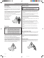
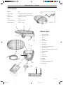
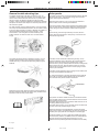
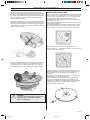
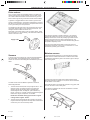
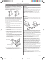
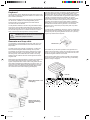
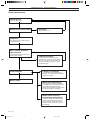
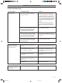
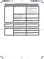
Solar Mower
Workshop Manual
101 88 90-26
Eng-SOL VERK front
1
98-01-15, 10.06
LIST OF CONTENTS
!
WARNING!
This tool can be dangerous if used incorrectly.
Warnings and safety instructions in this
Workshop Manual must be followed carefully
for the tool to be used safely and efficiently.
List of Contents
Safety instructions
User safety .......................................................................... 2
Tool safety ........................................................................... 2
Working safety ..................................................................... 2
Technical data
!
!
!
WARNING!
Keep hands and feet away from the rotating
blades.
Never place your hands or feet close to, or
under the cutting deck’s cover before you
have checked that the power switch is off and
that the motor has stopped.
WARNING!
Do not permit anyone who does not know how
the lawn mower works or behaves to carry out
repairs on the lawn mower.
WARNING!
Under no circumstances may the lawn mower’s original design be modified without the
permission of the manufacturer. Always use
genuine spare parts. Non authorised modifications and/or components can result in serious
disruptions and the risk of personal injury.
Technical data ..................................................................... 3
What is what? ...................................................................... 3
Trouble shooting
General trouble shooting tips .............................................. 4
Solar panels ........................................................................ 4
Motor and cutting disc ......................................................... 5
Drive motors ........................................................................ 6
Sensors ............................................................................... 6
Moisture sensor ................................................................... 6
Microswitches (Collision detectors) ..................................... 7
Cables ................................................................................. 7
Batteries .............................................................................. 7
Keyboard ............................................................................. 8
Generator and loop cable .................................................... 8
Circuitboard with CPU ......................................................... 9
Buzzer ................................................................................. 9
Main power switch ............................................................... 9
Magnetic switch ................................................................... 9
Start-up sequence ............................................................. 10
Trouble shooting chart ....................................................... 11
Circuit diagram
Circuit diagrams ................................................................ 13
IMPORTANT!
Read through the Workshop Manual carefully and understand the contents before
starting to carry out any repairs. Follow all
directions.
English –
Eng-SOL VERK
1
98-01-15, 10.07
1
SAFETY INSTRUCTIONS
User safety
Working safety
• Read carefully through this Workshop Manual to understand
all the repair directions.
• Check that there are no stones, twigs, tools or other objects,
which can damage the blades, on the lawn to be used as a
test surface.
• Those not familiar with how the lawn mower works or behaves
should not be allowed to repair the tool. They should not be
allowed to be within the vicinity of, or in the lawn mowers
working area when the mower is activated.
• Never permitted anyone to touch the lawn mower when in use.
!
WARNING! Always switch off the lawn mower
using the power switch before inspecting,
cleaning or carrying out repairs.
• Never move the lawn mower with the rear panels folded down.
Switch off the lawn mower using the power switch when
moving outside of the cutting area or if maintenance shall be
carried out.
• Always wait until the blades have stopped. Carry it by using
the handle and with the rear panels folded up.
• Never use the lawn mower
with damaged panels,
covers or cables.
• When moving over short distances the lawn mower can be
switched off by folding up the rear solar panel and waiting until
the blades have stopped. Carry it by using the handle and with
the rear panel folded up.
• Never use the lawn
mower if the power
switch does not work.
• Never use the lawn mower with defective covers, screws, nuts
or cables.
• Start the lawn mower according to the instructions. Keep
hands and feet away from the rotating blades. Never place
your hands or feet under the solar panels.
• Do not stand in front of the lawn mower when you start it, also
ensure than no one else is standing in front of the lawn
mower.
• Never lift up the lawn mower or carry it around when it is
running.
Tool safety
!
WARNING!
Always switch off the lawn mower using the
power switch before inspecting, cleaning or
carrying out repairs. The batteries should
always be disconnected when carrying out
maintenance or repairs to the lawn mower’s
internal components. The only exception is
when current or voltage needs to be measured. Extra care should then be exercised.
• Replace damaged parts. Check especially that the blades and
cutting disc are not damaged. Change all the blades at the
same time so that rotating parts are balanced.
• The lawn mower contains environmentally hazardous batteries. In accordance with applicable laws regarding spent
batteries: These must not be thrown in household waste or
mixed with industrial waste. Those who professionally sell
batteries or such equipment where such batteries are included, are obliged to accept spent batteries and thereafter
leave then to an approved authority for disposal.
• Always switch off the lawn mower using the power switch
before inspecting or cleaning the underside or carrying out
repairs.
Care and storage safety
• Store the lawn mower in an area that is dry but not too warm,
otherwise damage can be caused to the solar panels and
batteries.
• During the winter the lawn mower should be stored in a dry
place, preferably in the original packaging or parked on all four
wheels, with the power switch off and the batteries disconnected.
Transport safety
• Fold up the rear section of the solar panel and switch off the
power switch when transporting the lawn mower. Use the
original packaging when transporting the lawn mower over
longer distances.
2 – English
Eng-SOL VERK
2
98-01-15, 10.07
TECHNICAL DATA
Technical data
Batteries
NiCd
Cutting system
Cutting disc with three flexible blades
Wheels
Front wheels with stainless steel bearings
Height control
Variable, 30 - 60 mm
Weight
6.5 kg
Length/Width/Height
105cm/63cm/22cm
Working capacity
1200 m2 +- 20%
3
2
1
What is what?
7
5
4
8
10
9
1.
Front solar panel
2.
Rear solar panel
3.
Hinge
4.
Bumper
5.
Front wheels
6.
Cutting disc
7.
Drive wheel
8.
Handle and rear panel support
9.
Moisture sensor
10. Electronic controller with microprocessor
11. Protective plate
18
12. Frame
6
13. Keyboard
14. Power switch
15. Sensor
11
17
16. Generator
15
17. Operator’s Manual with code
12
16
18. Loop cable
13
14
English –
Eng-SOL VERK
3
98-01-15, 10.07
3
TROUBLE SHOOTING
General trouble shooting tips
Solar panels
The dealer should have a test lawn of a least 5 x 5 m, surrounded by a loop cable and generator. This test lawn can be
used in those cases where the customer has a problem with
the lawn mower not detecting signals from the loop cable.
Thereby making it possible to determine whether the operating
disruptions are due to metal objects or electrical power lines in
the customer's garden.
A number of solar panels connected together transform daylight
into electrical energy. This electrical energy drives the lawn
mower and charges the batteries.
So called “islands“ (see the diagram below), which are formed
with a loop around flowerbeds, fountains, etc. should be routed
in the loop cable’s direction and have a diameter of at least 2 m
(see the Operator’s Manual) to ensure its function. If the
commands F1-9 are changed to increase sensitivity then
smaller “islands“ can also be made, carry out tests before
burying the loop cable.
All trouble shooting should be preceded by at least 1 hour of
charging (with the switch in the off position) outdoors in the
middle of the day, to eliminate the fault being badly charged
batteries.
When the lawn mower is in the sun its rays are sufficient to
drive the lawn mower and charge the batteries.
The microprocessor is also used to measure the voltage levels
from the solar panels, and thereby determine whether the lawn
mower has gone into the shade or whether dusk is approaching.
In the evening, when the light intensity is too low, the lawn
mower stops and signals with 1 beep every 10 seconds. This
indicates the night mode.
If the lawn mower avoids the shade during the day, it is because the batteries at the present time do not have sufficient
capacity and to also ensure a long operating time. Large
amounts of sun (sunny weather) allow the mower to charge fully
before it starts to move, while small amounts of sun (cloudy)
means that it charges a little and then moves hoping to find a
sunnier part of the lawn.
If the lawn mower frequently stops to charge in the shadow, this
is a sign that the batteries are deficient.
To check the operation of the solar panels the jointing sleeves
535 03 86-01 should be dismantled and the current from the
front and rear solar panels should be measured.
535 03 86-01
Read through the entire Workshop Manual and the Operator’s
Manual to determine whether the fault is easily rectified via the
keyboard or with the main power switch.
The panel's connection cables should be connected as follows:
The red cable from the box to the red cable from the front of the
body (suitable length 85 mm).
The black cable from the box to the black cable from the rear of
the body (suitable length 55 mm).
The black cable from the front of the body to the red cable from
the rear of the body (suitable length 70 mm).
When the panels are connected together (in series) the cable
runs to the box and is connected to the connector X1 at terminals
6 (black) and 7 (red). See the circuit diagram on the last page.
As the light intensity can vary a great deal it is difficult to specify
an exact current, however, if a different current is measured from
the front and rear solar panels at the same time, you may
presume that the panel that generates the lowest current is faulty.
4 – English
Eng-SOL VERK
4
98-01-15, 10.07
TROUBLE SHOOTING
The panel can still work despite one of the segments being
damaged, but then gives a lower capacity. This can mean that
the machine frequently stands still and charges, even on very
sunny days. Or the lawn mower can stand still and beep once
every 10 seconds, which is the night mode signal, despite it
being the middle of the day.
No objects should be placed on top the panels for these to give
maximum electrical energy. Panels should be cleaned using a
damp sponge and a soap solution/hand washing up detergent
when surfaces are dusty or dirty and during the pollen season
or with similar daily soiling.
Motor and cutting disc
A 12V AC motor with controlled speed (max 2500 r/min) is used
as the cutting motor. The cables from the motor are connected
to connector X1 on the terminals 1-5 on the circuitboard in the
box. Registration of the motor speed is made by using a
tachometer which sends signals to the microprocessor on the
circuitboard in the box.
The speed measurement is made to “measure“ the length of the
grass (mowing resistance).
If the mowing resistance momentary exceeds the mean value
for the last few minutes the lawn mower can move in a spiral
pattern, to mow areas that have longer grass than average.
When the lower mower senses a drastic reduction in the
mowing resistance, or if an obstacle comes in its way, it returns
to its normal movement pattern.
Great care should be exercised when handling the panels due
to their low weight and fragility. This is especially important
when the lawn mower is turned upside down, e.g. when the
cutting height needs to be adjusted (see the diagram below).
The cutting height can be adjusted variably between 30-60 mm.
Adjust the height by loosening the orange coloured knob and
move the entire cutting unit upwards or downwards in its
mountings.
The cutting disc is bolted to the cutting motor’s shaft and holds
3 blades thrown out by centrifugal force.
These blades are mounted in blade holders (coloured red) to
allow them to be easily attached to or dismantled from the
cutting disc. The design of the blade holders ensures that the
blades are well secured if a collision with small objects, e.g.
twigs on the lawn, should occur.
!
WARNING!
The blades are extremely sharp. Always wear
protective gloves when working with the
blades or cutting disc.
English –
Eng-SOL VERK
5
98-01-15, 10.07
5
TROUBLE SHOOTING
Drive motors
Two, 12 V DC motors with reversible direction of rotation are
used to drive the lawn mower forwards. The two drive motors
can rotate in different directions at the same time to give the
lawn mower a tight turning circle and increase manoeuvrability.
A gearbox is engaged after the drive motors to give the lawn
mower increased traction. The speed is registered by a tachometer which is connected to the motors. The speed of the motors
is then governed by the microprocessor.
The cables from the drive motors are connected to the connector X9 (left) and X8 (right) on the circuitboard in the box. The
voltage to the drive motors should be 12 V.
Red cable (+) and black cable (-) are the supply cables. These
can be fed with 12 V for test driving. The other three cables are
used to control the motor.
The sensor is sensitive to moisture and dirt. If, for example,
grass sticks between the sensor's pins this will cause signal
leakage and the lawn mower will possibly signal that it cannot
sense a signal from the loop cable (3 beeps/second). The
unused (smaller) pin can be cut off and insulated using silicon if
the problem frequently recurs.
Supply cable
The part of the cable harness that runs from the sensor is
connected to terminals 15 and 16 on the connector X1 on the
circuitboard. (Arbitrary pole reversal.)
Moisture sensor
Sensors
A sensor (coil) is mounted on top of the front bracket between
the front wheels, see the diagram below, so that the lawn
mower can sense the electromagnetic field emitted by the loop
cable.
Using the keyboard (press C0) you can activate the moisture
sensor which is located under the box so that the lawn mower
can determine whether the grass is too moist to give an acceptable mowing result.
Sensor
The lawn mower uses two different systems to sense the
electromagnetic field:
1.
The lawn mower should, with a loop length of 300 m – at a
distance of max. 35 meters from the loop cable (see
diagram) sense that the loop cable is generating an
electromagnetic field, see diagram, (with a 500m loop
length - max 25 m). If it does not sense the electromagnetic
field an error signal, 3 beeps/sec. is sounded.
A copper rivet and a zinc plate form a galvanic element that
when wet generates a voltage of 0.7V, which can be measured
on the cables on the inside.
The moisture sensor only measures moisture in long grass, that
is, it will not react to short, moist grass.
The cables connected to the rivet are connected to connector
X5 on the circuitboard.
NOTE! The maximum cutting area to achieve a good
cutting result is approx. 1200m2.
2.
The lawn mower should sense the increase in the electromagnetic field as it approaches the loop cable and because
of this turns just in front of the loop cable.
Cable
6 – English
Eng-SOL VERK
6
98-01-15, 10.07
TROUBLE SHOOTING
Microswitches (Collision detectors)
Cables
The front panel’s rear edge is suspended in two, spring-loaded
aluminium levers.
These levers in turn activate two microswitches which are
integrated in the “housings“ (see the diagram below) that
connect the front panel with the box.
The cables are used to connect all the electrical components on
the lawn mower that concern, propulsion, charging, communication and mowing.
The microswitches are activated when the bumper on the front
of the lawn mower hits an obstacle. These give a signal to the
microprocessor that tells the lawn mower to back away. The
lawn mower determines whether to reverse straight back and
then turn to the left or right depending on whether the righthand, left-hand or both microswitches are activated.
When checking whether a cable break has occurred all connections must be removed before each individual cable is resistance measured using a multimeter.
For operations to be good, bearing in mind the short cable
lengths in question, the resistance in the cables should be 0
ohm.
Batteries
Two, series connected 6V Nickel-Cadmium batteries are used
in the lawn mower. One, 2.4V Nickel-Cadmium battery is used
in the generator.
If you wish to check whether the microswitches are functioning
proceed as follows:
1.
Check that the microswitches ”click” when the levers are
pressed back.
2.
Dismantle the black cover plates on the sides of the
microswitches.
3.
Check that the levers (535 03 29-01) are not bent and that
they run parallel to the side of the microswitch housing.
4.
Check that the microswitch’s arm can move freely in the
hole against lever.
5.
Measure the voltage (the main power switch in position “1“)
between the earth (the box) and one of the cables on the
microswitch. The voltage should be 5.0-5.1 V on one pin
and 0 V on the other.
The batteries are used in the lawn mower to power the “computer“, i.e. the circuitboard with microprocessor, even at night to
ensure that the theft alarm works. The batteries also act as a
buffer when the lawn mower is mowing in the shade or during a
cloudy or a partially sunny day. This is why the lawn mower can
still mow for short periods on cloudy days.
Press the lever backwards, the voltage should be between
5.0 - 5.1 V between the earth and the connected cables. If
a voltage value lower than 5 V is obtained then the
microswitch is defective and should be replaced (presupposes charged batteries).
In the generator, the battery ensures that the loop is generating
an electromagnetic field even when the sun is not shining
sufficiently to power the generator. It is important that the
generator is placed where it is well lit.
If the lawn mower requires long charging times on very sunny
days and, despite this, only has a short operating time, it’s
reasonable to suspect that the batteries need to be replaced.
The batteries in the lawn mower should be changed in pairs to
guarantee operations, as a new battery with a relatively old
battery will reduce capacity and in some cases completely
destroy the new battery. If changing the batteries does not help,
check whether the solar panels are functioning correctly.
Microswitch
Another sign that the batteries are discharged is when the lawn
mover frequently stops in the shade to charge.
535 03 29-01
6.
Also check that the cables from the microswitch are
correctly made in terminals 8-11 on connector X1 on the
circuitboard. Right 8 (+) 9 (-) and left 10 (+) 11(-).
If the lawn mower has difficulties in sensing the electromagnetic
field from the loop cable when it’s cloudy, at daybreak or dusk,
the battery in the generator may need to be replaced, see page
2. Thereafter check that the cables outside and inside the
generator are in working order, and that there are no loose
connections.
The lawn mower stands in the charging mode (2 beeps/10
seconds) for a maximum of 40 minutes, irrespective of whether
the batteries are fully charged or not.
English –
Eng-SOL VERK
7
98-01-15, 10.07
7
TROUBLE SHOOTING
Keyboard
The keyboard is used to deactivate the theft alarm and to enter
the security code and to change limit values for a number of the
lawn mower’s parameters.
If the keyboard ceases to beep when the keys are pressed this
can be due to, in addition to a discharged battery and/or
insufficient light, bad contact between the cables and the
connectors on the circuitboard.
The keyboard is attached to the box using self-adhesive tape,
which is why care should be exercised when the keyboard is
replaced and must be removed. All remaining adhesive should
be removed using acetone or a similar solvent but not white
spirit, to ensure the new keyboard is correctly attached.
!
If the loop cable is correctly connected a signal should be given
when the momentary switch on the generator makes. If the
generator does not give a signal, start by bridging the generator
using a piece of cable and make the generator's switch again. If
a signal is now heard then the loop cable is not correctly
connected or there is a break in the loop cable. Start by checking the cable's connection to the generator. If the cable is
corroded, cut and strip it so that a good contact is obtained.
Measurement of the loop cable's resistance is carried out with
the cable disconnected from the generator. The resistance
should be max. 2 ohm/100m per loop cable (max. loop cable
length is 500 m).
If a cable break is established, (R=infinity), start by checking the
joints and the transition between ground and air. (For damp and
oxide-proof joints use jointing sleeves 535 04 43-01.) Use only
original loop cables from Husqvarna.
WARNING! The box must not be washed while
electronic equipment is fitted.
Generator and loop cable
The generator is used together with the loop cable to form an
electromagnetic enclosure that the lawn mower senses and
keeps within.
The lawn mower gives a signal of 3 beeps/sec. if it does not
sense the electromagnetic field emitted by the loop cable.
The problem can be due to the sensor under the front of the
lawn mower being faulty, or the generator and/or loop cable
also being faulty. If the cable has been routed in the wrong
direction around "islands" then this will extinguish the electromagnetic field.
Metal objects and electrical cables on the lawn can weaken the
loop cable's electromagnetic field. If the lawn mower only
signals 3 beeps/second in certain areas of the garden this can
mean that it's experiencing a disturbance in just this area. Try
moving the loop cable. Sharp bends (90 degrees) in the loop
cable bring about a weakened electromagnetic field and this
can result in the lawn mower escaping (see diagram).
535 04 43-01
The easiest way to check the operation of the generator is to
measure the current flow in series with a functioning loop cable.
There is a risk, with a measurement value under 7mA AC, that
the electromagnetic field will be too weak.
Check that the cables and connections inside of the generator
are correct. Another quick check is to test using a new battery
(allow to charge in daylight).
A
Sharp cable bends = risk
of escaping.
Gentle bends give a
stronger electromagnetic field.
8 – English
Eng-SOL VERK
8
98-01-15, 10.07
> 7mA AC
TROUBLE SHOOTING
Circuitboard with CPU
Main power switch
The circuitboard together with the CPU (microprocessor) are
the lawn mower’s “brain“ and handle all functions, commands
and path selections the lawn mower decides on, based on the
input data provided by the keyboard, sensors, solar panels,
microswitches (collision detectors) and the batteries charge
status.
The main power switch ensures that the lawn mower does not
start when it is switched off. The code must be entered in the
lawn mower every time the main power switch has been
switched off, even some commands are reset (see the Operator's Manual). Note that the switch does not cut the voltage from
the batteries and solar cells. Accordingly, the batteries' connection cables should be disconnected when working inside the
box and during the winter storage period.
To check whether an operating disruption is due to an error in
the microprocessor start by resetting it 3 times (preceded by
charging in daylight for at least 1 hour). That is, remove and
reconnect one of the batteries connectors 3 times, allowing 5
seconds to elapse in between.
The main power switch can be checked by measuring its
resistance. The resistance should be 0 ohm respective infinite
resistance depending on the position of the switch.
Also check that the fuses on the circuitboard have not blown
and that they make good contact in the fuse holders. Replace
fuses carefully.
The voltage between the fuses and the earth can also be
measured and should be the same as the actual battery
voltage. (The main power switch in position “1“.)
If this does not solve the problem you can try replacing the
microprocessor with a microprocessor that you know functions
correctly. The processor must be lifted out using the processor
tool, otherwise there is a large risk of damaging the processor
pins.
NOTE! All work on or in connection with the circuitboard
must take place with the batteries disconnected to avoid
short circuiting. Static electricity can also damage the
microprocessor.
Magnetic switch
The magnetic switch is located by the hinge between the front
and rear solar panel halves and ensures that the lawn mower
does not start until the rear solar panel has been lowered.
The magnetic switch can be checked by putting the power
switch in the “on” position and then lowering the rear solar
panel. When this is done a click should be heard from the relay
on the circuit board and the machine indicates “start-up” (1
beep/second) for 10 seconds. If you hear this the magnetic
switch functions correctly.
If the “start-up” does not start, temporarily strap the connection
screws on the magnetic switch. If the “start-up” now starts the
magnetic switch is defective.
For information on how to replace the magnetic switch refer to
service notice tab 5, 96.016.
When trouble shooting, a microprocessor with the article
number 535 04 90-01 can be used, all have the code “A 00000
B“. This microprocessor shall only be used for trouble shooting
and repair work.
All other trouble shooting (in addition to replacing the
circuitboard) consists of checking that connectors and cables
are connected correctly on the circuitboard, even dampness
and dust can result in faults, which is why cleaning with a dry
brush and drying indoors can solve basic problems with short
circuiting. Ocular inspection can also reveal the reason for a
fault.
Buzzer
The lawn mower has a buzzer on the outside of the box that
generates a beep, which the machine uses to interact with the
user. The buzzer's volume can be adjusted using B0 - B9,
where B9 gives a louder signal and B0 mutes the buzzer. If
these setting have no effect on the volume, try replacing the
buzzer. Connect 12 V DC to the buzzer to check whether it
functions; it should sound.
There is also a buzzer on the circuit board, which has a fixed
volume. If you wish the machine to be completely silent this
must be blocked. This is done by pressing silicon into the hole
on the top of the buzzer. Note this will also mute the beep heard
when pressing the keys.
English –
Eng-SOL VERK
9
98-01-15, 10.07
9
TROUBLE SHOOTING
Start-up sequence
Charge 60 min
Switch in "off" position.
Switch on the power switch
No sound
Battery level too low.
Long beep
The batteries have enough power to
run the electronics.
Wait 1 minute and then
enter the code
A short beep should be heard when
pressing every button.
Code not accepted
A long beep when pressing "B" indicates that the mower has not registered
the code, but will run for 2 minutes and
then stop, probably signalling "no code"
(2 beeps/second).
2 beeps / 10 seconds
Code accepted
This indicates that the batteries are
charging. The mower will start automatically when charged.
Mower starts
Mower starts backwards
When stopping it will signal "trapped"
(1 beep/second). This indicates that the
microswitches are jammed. Other
failures when signalling "trapped" might
be blocked wheels or cutting disc.
Mower starts and then
stops almost immediately
The mower will signal 2 beeps/second.
There is not enough power to run the
mower properly. Charge another 60
minutes. If this is not enough, replace
the batteries.
10 – English
Eng-SOL VERK
10
98-01-15, 10.07
TROUBLE SHOOTING
Trouble shooting chart
Observation
Possible cause
Action
3 beep/second
The lawn mower does not sense the
signal from the loop.
Check that the cable is not broken (by
using the operating test on the generator).
Check the sensor, wipe off any grass or
moisture on the cable connections. Ensure
the cover is fitted. If the problem frequently
recurs cut off the unused pin and insulate
using silicon (see service notice tab 5,
96.018).
Measure the current in the loop cable.
There is a risk that the electromagnetic
field is too weak with values under 7 mA
AC.
The lawn mower jerks
forwards and backwards
and swings quickly.
The lawn mower stops
frequently to charge when
in the shade.
If this occurs in isolated areas it can be
caused by disturbances from metal
objects (fencing, reinforcement) or by
underground cables in the vicinity.
Try moving the loop cable.
If it occurs in the vicinity of an “island”, it
can be due to the loop cable be routed in
the wrong direction around the “island”
and thereby extinguishing the signal.
Check that the loop cable has been laid
according to the instructions in the Installation guide.
If it only occurs in the morning it can be
caused by the battery in the generator
being discharged.
Replace the generator battery.
The electronics were started at too low
voltage.
Reset the processor by disconnecting and
reconnecting one of the batteries 3 times.
The microswitches switch too easily,
e.g. at corners or over bumps.
Check that the microswitches do not
switch before a tractive force of approx.
10N is applied.
Play on the drive motors' contact
connections.
Check the drive motors' circuit board
connection.
Faulty gearbox on a drive motor or
faulty tachometer (hall element) on a
drive motor.
Try by replacing one drive motor at a time.
Electronic fault.
Replace the circuit board.
The batteries have discharged.
Replace the batteries.
English –
Eng-SOL VERK
11
98-01-15, 10.07
11
TROUBLE SHOOTING
The lawn mower
escapes.
The signal from the loop is not strong
enough.
Check the sensor, wipe off any grass or
moisture on the cable connections.
Ensure the cover is fitted. If the problem
frequently recurs cut off the unused lug
and insulate using silicon (see service
notice tab 5, 96.018).
Measure the current in the loop cable.
There is a risk that the electromagnetic field
is too weak with values under 7 mA AC.
If this occurs in isolated areas it can be
caused by disturbances from metal
objects (fencing, reinforcement) or by
underground cables in the vicinity.
Try moving the loop cable.
The loop cable is bent sharply
(90 degrees).
Lay the loop cable so that the bend is
gradual.
Loop cable is too deep.
Move the loop cable.
The code must be
enter frequently.
The electronics have temporarily lost its
voltage, and interprets this as if the lawn
mower has been switched off.
Check the battery connection the circuit
board.
1 beep/second
The cutting disc is blocked.
Check that the disc can rotate freely.
The drive wheel is blocked.
Check whether something is blocking the
drive wheel.
The lawn mower starts to reverse when
it is switched on.
A microswitch has jammed. Check and
rectify.
12 – English
Eng-SOL VERK
12
98-01-15, 10.07
Magnetic switch
Eng-SOL VERK
13
Cutting motor
Black
Red
Black
Black
Red
Red
Rear body
Front body
CIRCUIT DIAGRAM
English –
98-01-15, 10.07
13
We hope you find the links below useful. For further gardening information visit
www.GardenResources.co.uk
Blower Vacs
Cultivators
Electric
chainsaws
Garden tractors
Hover mowers
Lawn scarifiers
Petrol hedge
cutters
Ryobi strimmers
Brush cutters
Cylinder lawn
mowers
Fertiliser
spreaders
Garden vacuums
Husqvarna
chainsaws
Lawn tractors
Ride on lawn
mowers
Scarifiers
Brushcutters
Cylinder mowers
Chainsaws
Echo chainsaws
Chain saws
Echo Strimmers
Garden blowers
Garden rollers
Garden shredders
Hayter lawn
mowers
Kawasaki brush
cutters
Leaf blowers
Ride on mowers
Hedge cutters
Hedgecutters
Kawasaki
strimmers
Leaf vacuums
Rotary mowers
Lawn mowers
Petrol chainsaws
Rotavators
Westwood lawn
tractors
Blower Vacs
Westwood ride on
mowers
Chain Saws
Strimmers
Westwood
tractors
Chainsaws
Brush Cutters
Brushcutters
Cultivators
Echo Chainsaws
Echo Strimmers
Electric
Chainsaws
Garden
Shredders
Hedgecutters
Fertiliser
Spreaders
Garden Tractors
Cylinder Lawn
Mowers
Garden Blowers
Garden Rollers
Lawn Rollers
Garden Vacuums
Hedge Cutters
Lawn Mowers
Petrol Chainsaws
Scarifiers
Petrol Hedge
Cutters
Ryobi Strimmers
Hayter Lawn
Mowers
Kawasaki Brush
Cutters
Leaf Blowers
Ride on Mowers
Rotovators
Patio Heaters
Gas Greenhouse
Heaters
Christmas
Gardening Gifts
Hover Mowers
Patio Heater
Covers
Stainless Steel
Patio Heaters
Garden Tractors
Husqvarna
Chainsaws
Lawn Tractors
Ride on Lawn
Mowers
Garden Patio
Heaters
Garden Heaters
Table Top Patio
Heaters
Ride on Lawn
Mowers
Outdoor Patio
Heaters
Greenhouse
Heaters
Patio Heaters UK
Ride on Mowers
Also See
Gardening Tools Direct, for lawn mowers, brush cutters, chainsaws
Gardening Supply for patio heaters, lawn mowers, chainsaws
Garden Tractor, for lawn tractors and ride on mowers
Kawasaki
Strimmers
Leaf Vacuums
Rotary Mowers
Gas Patio Heaters
Green House
Heaters
Patio Heaters with
Covers