1
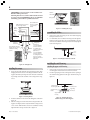
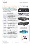
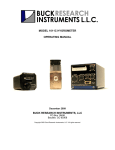
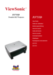
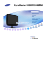
1
© 2005 Hunter Fan Company
41877-01 06/14/2007
2
®
Your new Hunter® ceiling fan is an addition to your home or office
that will provide comfort and performance for many years. This
installation and operation manual gives you complete instructions
for installing and operating your fan.
We are proud of our work. We appreciate the opportunity to supply you with the best ceiling fan available anywhere in the world.
Before installing your fan, record the following information for your
records and warranty assistance. Please refer to the carton and the
Hunter nameplate label (located on the top of the fan motor housing) for the proper information.
Model Name: __________________________
Catalog/Model No.: ______________
Serial No.: _____________________
Date Purchased: ___ / ___ / ______
Where Purchased: _______________________________
Please also attach your receipt or a copy of your receipt for reference.
cautions and warnings
•
•
•
•
•
•
•
Read entire booklet carefully before beginning installation. Save these instructions.
Use only Hunter replacement parts.
To reduce the risk of personal injury, attach the fan
directly to the support structure of the building according to these instructions, and use only the hardware supplied.
To avoid possible electrical shock, before installing
your fan, disconnect the power by turning off the circuit breakers to the outlet box and associated wall
switch location. If you cannot lock the circuit breakers in the off position, securely fasten a prominent
warning device, such as a tag, to the service panel.
All wiring must be in accordance with national and
local electrical codes and ANSI/NFPA 70. If you are
unfamiliar with wiring, you should use a qualified electrician.
To reduce the risk of personal injury, do not bend the
blade attachment system when installing, balancing,
or cleaning the fan. Never insert foreign objects between rotating fan blades.
To reduce the risk of fire, electrical shock, or motor
damage, do not use a solid-state speed control with
this fan. Use only Hunter speed controls.
getting ready
To install a ceiling fan, be sure you can do the following:
• Locate the ceiling joist or other suitable support in ceiling.
• Drill holes for and install wood screws.
• Identify and connect electrical wires.
• Lift 40 pounds.
If you need help installing the fan, your Hunter fan dealer can direct you to a licensed installer or electrician.
gathering the tools
You will need the following tools for installing the fan:
• Electric drill with 9/64" bit
• Standard screwdriver
• Phillips-head screwdriver
• Wrench or pliers
considering optional accessories
Consider using Hunter’s optional accessories, including a wallmounted or remote speed control. To install and use the accessories, follow the instructions included with each product. For quiet
and optimum performance of your Hunter fan, use only Hunter
speed controls.
checking your fan parts
Carefully unpack your fan to avoid damage to the fan parts. Check
for any shipping damage to the motor or fan blades. If one of the
fan blades was damaged in shipment, return all the blades for replacement.
NOTE: If you are installing more than one fan, keep the fan blades
in sets, as they were shipped.
If any parts are missing or damaged, contact your Hunter dealer or
call Hunter Parts Department at 888-830-1326.
choosing your mounting position
Standard Mounting (Figure 1) hangs from the ceiling by a downrod
(included), for ceilings 8 feet or higher. For ceilings higher than 8
feet, you can purchase Hunter extension downrods. All Hunter fans
use sturdy 3/4" diameter pipe to assure stability and wobble-free
performance.
12”
Figure 1 - Standard mounting
41877-01 06/14/2007
© 2007 Hunter Fan Company
3
Angle Mounting (Figure 2) hangs from a vaulted or angled ceiling.
using an existing fan site
If you are preparing a new fan site, go to the preparing a new fan
site section.
If you plan to use an existing fan site, complete the following checklist
for the support brace, ceiling hole, outlet box, and wiring. If you cannot check off every item, see the preparing a new fan site section
for instructions on properly preparing the site for your new fan.
34º Max
8
Pitch
12
fan support system
•
•
Fan must attach directly to building structure.
Fan support system must hold full weight of fan and light
kit.
ceiling hole
•
Figure 2 - Angle mounting
outlet box
•
preparing the fan site
These guidelines are designed to help you select the best location
for your fan and to prepare the site prior to installing the fan. Proper
ceiling fan location and attachment to the building structure are
essential for safety, reliable operation, maximum efficiency, and
energy savings.
Within the room where you want to install the fan, choose a fan
site where:
• No object can come in contact with the rotating fan blades
during normal operation.
• The fan blades are at least 7 feet above the floor and the
ceiling is at least 8 feet high.
• The fan blades have no obstructions to air flow, such as
walls or posts, within 30 inches of the fan blade tips.
• The fan is directly below a joist or support brace that will
hold the outlet box and the full weight of the fan.
See Figure 3 for the minimum mounting distances.
30” From
Wall or
Nearest
Obstruction
7’ Minimum
to Floor
•
•
•
choosing the fan site
8’ Minimum
Ceiling Height
Outlet box clearance hole directly below the joist or support brace.
UL-approved octagonal 4" x 1-1/2" outlet box listed as
“suitable for outdoor use” (or as specified by the support
brace manufacturer).
Outlet box secured to joist or support brace by wood
screws and washers through inner holes of outlet box.
Outer holes of outlet box aligned with joist or support
brace.
Bottom of outlet box recessed a minimum of 1/16" into
ceiling.
wiring
•
Electrical cable secured to outlet box by approved connector.
• Six inches of lead wires extend from outlet box.
See Figure 4 for an adequate existing fan site.
Support Brace
Ceiling Joist
Approved
Connector
Washer
Wood Screw
Ceiling
Outlet Box
Figure 4 - Adequate existing fan site
If your existing fan site is suitable, go to the installing the ceiling
plate section and begin installing your new Hunter fan.
preparing a new fan site
Figure 3 - Minimum mounting distances
41877-01 06/14/2007
To prepare the fan site follow four steps:
• Cutting the Ceiling Hole
• Installing the Support Brace (if necessary)
• Installing the Outlet Box
• Preparing the Wiring
© 2007 Hunter Fan Company
4
cutting the ceiling hole
1.
2.
preparing the wiring
Locate the site for the hole directly below the joist or support
brace that will hold the outlet box and fan.
Cut a 4" diameter hole through the drywall or plaster of the
ceiling as shown in Figure 5. You will use the hole to install the
support brace and outlet box.
1.
Ceiling Joist
Support Brace
2.
3.
4”
Diameter
Ceiling
Hole
Ceiling
4.
CAUTION: All wiring must be in accordance with national and local electrical codes and ANSI/NFPA 70. If you
are unfamiliar with wiring, you should use a qualified electrician.
Make sure the circuit breakers to the fan supply line leads and
associated wall switch location are turned off. If you cannot
lock the circuit breakers in the off position, securely fasten a
prominent warning device, such as a tag, to the service panel.
Thread the fan supply line through the outlet box so that the
fan supply line extends at least 6" beyond the box as shown in
Figure 7.
Attach the fan supply line to the outlet box with an approved
connector, available at any hardware store or electrical supply
house. Refer to Figure 7.
Make certain the wiring meets all national and local standards
and ANSI/NFPA 70.
Approved
Connector
Figure 5 - Cutting the ceiling hole
installing the support brace
If there is a ceiling joist directly above the hole which will allow the
outlet box to be recessed a minimum of 1/16" in the ceiling, go to
installing the outlet box section.
If there is not an adequate ceiling joist available, do the following:
1. Attach a 2" x 4" support brace between two joists. The support brace must allow the bottom of the outlet box to be recessed a minimum of 1/16" into the ceiling. See Figure 6.
2. Check the support brace to ensure it will support the full weight
of the fan and light kit.
installing the outlet box
1.
2.
3.
4.
Obtain a UL-approved octagonal 4" x 1-1/2" outlet box, plus
two #8 x 1-1/2" wood screws and washers, available from any
hardware store or electrical supply house.
Orient the outlet box so that both the inner and outer holes in
the box align with the joist or support brace.
Drill pilot holes no larger than the minor diameter of the wood
screws (5/64") through the inner holes of the outlet box.
Attach the outlet box directly to the support brace or joist
with two #8 x 1-1/2" wood screws and washers. The bottom of
the outlet box must be recessed a minimum of 1/16" into the
ceiling as shown in Figure 6.
Wire Leads
Figure 7 - Preparing the wiring
You have now successfully prepared your ceiling fan site. For instructions on how to install your ceiling fan, continue with the installing the ceiling plate section.
installing the ceiling plate
1.
2.
3.
4.
Support Brace
5.
Washer
Wood Screw
Drill two pilot holes into the wood support structure through
the outermost holes on the outlet box. The pilot holes should
be 9/64" in diameter.
Place the ceiling gasket over the ceiling plate so that the slots
and raised surfaces on the ceiling gasket align with the slots
and holes on the ceiling plate.
Pierce holes in the neoprene through the slots in the ceiling
plate at a spacing to match the holes in the outlet box.
Thread the lead wires from the outlet box through the hole in
the middle of the ceiling plate.
Align the slotted holes (refer to Figure 8) in the ceiling plate
with the pilot holes in the wood support structure.
For Angled Ceilings: Be sure to orient the ceiling plate so that
the arrows on the ceiling plate are pointing towards the ceiling
peak. Refer to Figure 8.
Outlet Box
1/16" Recess
Figure 6 - Installing the outlet box
41877-01 06/14/2007
© 2007 Hunter Fan Company
5
Slots
Hanger Ball/
Downrod Assembly
Canopy
Arrows for Orienting
on Angled Ceiling
Adapter Cover
Figure 8 - Locating the slotted holes to use
6.
7.
Place a flat washer on each of the two 3" screws and pass the
screws through the slotted holes in the ceiling plate as shown
in Figure 9.
Tighten the screws into the 9/64" pilot holes; do not use lubricants on the screws. Do not overtighten.
Ceiling Joist
Set Screw
Figure 10 - Assembling the downrod
hanging the fan
1.
2" x 4" Brace
Ceiling Plate
Flat Washer
Raise the fan and place the hook through the loop on the ceiling plate as shown in Figure 11. Use the note and arrow engraved in the ceiling plate to assist in determining the direction to assemble.
WARNING: Fan may fall if not assembled as directed in
these installation instructions.
Celing
Outlet Box
3" Wood Screw
Hook
Loop
Figure 9 - Installing the ceiling plate
assembling the fan
assembling the fan for a standard or angled ceiling
1.
2.
3.
4.
Insert the pipe through the canopy and adapter cover with
the adapter ring assembled. To keep the adapter ring assembled, twist the adapter cover around the downrod. Refer
to Figure 12. Feed wires from the fan through the downrod.
Screw the downrod into the fan assembly until tight. IMPORTANT! Tighten downrod set screw as shown in Figure 10.
CAUTION: The downrod has a special coating on the
threads. Do not remove this coating; the coating prevents
the downrod from unscrewing. Once assembled, do not
remove the downrod.
Slide the adapter cover down by twisting it around the
downrod until it is flush to the top of the motor housing.
Continue to the hanging the fan section.
Figure 11 - Hanging the fan
wiring the fan
1.
2.
3.
41877-01 06/14/2007
Disconnect the power by turning off the circuit breakers to
the outlet box and associated wall switch location.
You can use either one or two wall switches to control the fan
and/or lights separately. Use connection 1, as described in Figure 12, to
• control the light with a wall switch and the fan with a pull
chain (one wall switch required),
• control the light with a pull chain and the fan with a wall
switch (one wall switch required), or
• control the light with one wall switch and the fan with
another (two wall switches required).
Use connection 2, as described in Figure 12, if there is no separate wall switch power wire for the light fixture.
NOTE: Wall switches not included.
Connect the wires as shown in Figure 12. To connect the wires,
twist the bare metal leads together. Place a wire nut over the
intertwined length of wire and twist clockwise until tight as.
© 2007 Hunter Fan Company
6
CAUTION: Be sure no bare wire or wire strands are visible after making connections.
All wiring must be in accordance with national and local
electrical codes and ANSI/NFPA 70. If you are unfamiliar
with wiring, you should use a qualified electrician.
Canopy Screw
(Note: Wall switch
must be acceptable
as a general-use
switch.)
Wall Switch Wire for Separate
Control of Light Fixture
Power
Wires in
Ceiling
Tab Hole
and Tab
Black
Figure 14 - Installing the canopy
White
assembling the blades
Bare or Green
1.
2 x 4 Brace
Outlet Box
2.
Ceiling Plate
Approved
Connectors
White
Black
1
Green Ground Wire from
Hanger Pipe (not present
with flush mounting
option)
2
Blk/Wht
3 Wires
from Fan
Connections:
1. Connect Blk/Wht
wire from the fan to
the wall switch for
separate control of the
light fixture, or
2. Connect Blk/Wht
wire from the fan to
the ceiling black wire if
there is no separate
wall switch wire for the
light fixture.
Figure 12 - Wiring the fan
Remove the blade mounting screws and rubber shipping
bumpers from the motor.
For each blade, insert one blade mounting screw through the
blade iron as shown in Figure 15, and attach lightly to the fan.
Insert the second blade mounting screw, then securely tighten
both mounting screws.
Figure 15 - Attaching the blade iron to the fan
installing the switch housing
attaching the upper switch housing
installing the canopy
1.
Rotate the fan 180º clockwise from the initial position when
hanging the fan. The arrows on the hanger ball and on the ceiling plate should be pointing in the same direction and should
be pointing towards the tab hole on the canopy. Refer to Figure 13.
1.
2.
Remove and save the three screws and lock washers from the
mounting plate located at the end of the motor shaft.
Feed the upper plug connector through the center opening of
the switch housing gasket and the upper switch housing. See
Figure 16.
Switch Housing
Mounting Plate
Switch Housing
Gasket
Housing
Assembly Screw
Upper Plug
Conntector
Upper Switch
Housing
Figure 13 - Rotating the fan
2.
3.
Hook the tab hole over the tab on the ceiling plate as shown in
Figure 14.
Raise the canopy, be sure the holes in the canopy and the ceiling plate are aligned, and loosely assemble the canopy screws
one at a time. When all three screws are assembled, securely
tighten all three canopy screws. Refer to Figure 14.
41877-01 06/14/2007
Figure 16 - Attaching the upper
switch housing to the mounting plate
© 2007 Hunter Fan Company
7
3.
Assemble the upper switch housing to the mounting plate
using the three screws and lockwashers which you removed
from the mounting plate. Tighten the screws securely.
CAUTION: Make sure the upper switch housing is securely attached to the switch housing mounting plate. Failure to properly attach and tighten all three housing assembly screws could result in the switch housing and light fixture falling.
Fitter Cover
Notch in
Globe
Assembly
Fitter
attaching the lower switch housing
1.
Connect the upper plug connector from the motor to the lower
plug connector in the lower switch housing assembly. See Figure 17.
NOTE: Both plug connectors are polarized and will only fit together one way. Make sure that both connectors are properly
aligned before connecting them together. Incorrect connection could cause improper operation and damage to the product.
Globe Assembly
Figure 18 - Installing the globe assembly
installing without the light fixture
1.
2.
Upper Switch
Housing
Lower Plug
Connector
Housing
Assembly
Screw
Upper Plug
Connector
3.
Lower
Switch
Housing
Install the upper switch housing as shown in the attaching
the upper switch housing section.
Disconnect the two single plug connectors in the lower switch
housing. Place the dummy terminals (in the sack parts) on the
end of each single plug connector. The female dummy terminal must be placed on the male plug connector and the male
dummy terminal on the female plug connector.
Remove the fitter assembly from the lower switch housing by
removing the two screws inside of the fitter as shown in Figure
19.
Figure 17 - Connecting the plug connectors
2.
Fitter
Place the lower switch housing assembly over the upper switch
housing. Align the side screw holes in the upper and lower
switch housings. Attach the lower switch housing to the upper switch housing with three #6-32 x 3/8" housing assembly
screws. See Figure 17.
installing the light fixture
1.
2.
3.
4.
Install the included CFL bulb.
Align the notches in the globe assembly with the bumps on
the fitter.
Twist the globe assembly clockwise until it locks in place.
Be sure that the holes in the fitter cover and globe assembly
align as shown in Figure 18. If they do not, remove the globe
assembly and begin with step 2 in a different position.
Remove these screws
Figure 19 - Removing the fitter assembly
4.
5.
Install the lower switch housing as shown in the attaching the
lower switch housing section.
Install the cap and plug button as shown in Figure 20.
Cap
Plug Button
Figure 20 - Installing the cap and plug button
41877-01 06/14/2007
© 2007 Hunter Fan Company
8
operating your ceiling fan
troubleshooting
1.
2.
Problem: Nothing happens; fan does not move.
1. Turn power on, replace fuse, or reset breaker.
2. Loosen canopy, check all connections according to the
wiring the fan section.
3. Check the plug connection in the switch housing.
4. Pull the pull chain to ensure it is on.
5. Remove the shipping bumpers.
Turn on electrical power to the fan.
The fan pull chain controls power to the fan. The pull chain
has four settings in sequence: High, Medium, Low and Off.
• Pull the chain slowly to change settings.
• Release slowly to prevent the chain from recoiling into
the blades.
• The chain uses a breakaway connector that separates if
the chain is jerked. If this happens, simply reinsert the chain
into the connector.
cleaning your ceiling fan
caring for finishes
For cleaning, a soft brush or lint-free cloth should be used to prevent scratching the finish. A vacuum cleaner brush nozzle can remove heavier dust. Surface smudges or an accumulation of dirt and
dust can easily be removed by using a mild detergent and a slightly
dampened cloth. An artistic agent may be used, but never use abrasive cleaning agents as they will damage the finish.
caring for blades
The painted and high-gloss blade holders may be cleaned in the
same manner as the fan finish. The sailcloth blade material should
be wiped off with a damp cloth.
Problem: Noisy operation.
1. Tighten the blade bracket screws until snug.
2. Tighten the blade screws until snug.
3. Check to see if the blade is cracked. If so, replace all the
blades.
4. Change to an approved speed control.
5. Check and tighten the screws in the switch housing
mounting plate and in the upper and lower switch housing.
Problem: Excessive wobbling.
1. If your fan wobbles when operating, use the enclosed balancing kit and instructions to balance the fan.
2. Tighten all blade and/or blade iron screws.
3. Turn power off, support fan very carefully, and check that
the hanger ball is properly seated.
If you need parts or service assistance, please call 888-830-1326 or
visit us at our WEB site at http://www.hunterfan.com.
Hunter Fan Company
2500 Frisco Avenue
Memphis, Tennessee 38114
41877-01 06/14/2007
© 2007 Hunter Fan Company