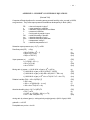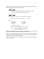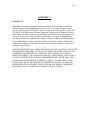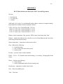
1
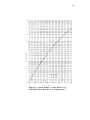
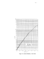
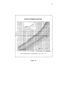
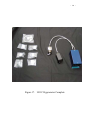
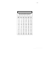
MODEL 1011C HYGROMETER
OPERATING MANUAL
December 2009
BUCK RESEARCH INSTRUMENTS, LLC
PO Box 19498
Boulder, CO 80308
Copyright 2008. Buck Research Instruments, LLC All rights reserved.
- 2 -
TABLE OF CONTENTS
1.0 INTRODUCTION
1.1 General Operational Description
1.2 Brief Physical Description
1.3 Specifications
1.4 List of improvements from the 1011B
1.5 Acknowledgment
p.5
2.0 CONTROLS, CONNECTORS, AND MAJOR COMPONENTS
2.1 Sensing Unit
2.2 Control/Indicator Unit
2.3 Power Unit
2.4 Cables
2.5 Optional Accessories
p.11
3.0 INSTALLATION
p.18
3.1 Unpacking Procedure
3.2 Initial Operation Check
3.3 Installation on Aircraft
3.4 Leak Check
3.5 Pressure Within Sensor
3.6 Cabling
4.0 OPERATING INSTRUCTIONS
4.1 Initial Setup
4.2 System Operation
4.2.1 Time Response
4.2.2 Mirror Cleanliness
4.2.3 Supercooled Dew Points
4.2.4 Low Frost Points
4.2.5 Pressure Effects
4.2.6 Typical Response to Humidity Changes
4.2.7 Mirror Flooding
4.3 Operation while Parked or off the Aircraft
p.24
5.0 PREVENTIVE MAINTENANCE AND TROUBLESHOOTING
5.1 Periodic Inspection
5.2 Cleaning System Optics
p.29
- 3 FIGURES
1
2
3
4
5
Model 1011C Dew Point Hygrometer System
Depression capability
Dew Point Sensing Unit
Control/Indicator Unit
Power Unit, External
p.7
p.9
p.12
p.14
p.15
6
7
8
9
10
Power Unit, Internal
Sensing Unit: Mounting and Assembly
Sensing Unit, Internal
Flow Test Fixture Hookup
System Response Characteristics
p.17
p.20
p.22
p.23
p.28
Appendix Figures:
11.
12
13
14
15
16
17
1011C Wiring Diagrams
Water Vapor Conversions
Vapor pressure vs. dew/frost point
Absolute humidity vs. dew/frost point
Effect of pressure on dew point
Aspirating Fixture Hookup
1011C Hygrometer Complete
p.31-2
p.33
p.34
p.35
p.36
p.37
p.38
- 4 LIST OF TABLES
Number
1
2
3
Title
1011C Connectors
Dew Point to Frost Point Conversions
Dew Point Error Due to Pressure Change in Sampling System
p.39
p.40
p.41
APPENDIXES
1
2
3
4
5
6
1011C Pin Out
Humidity Conversion Equations
Warranty
RS-232 outputs
Data outputs
Fan or heater connector on sensor
p.30
p.42
p.44
p.45
p.46
p,47
- 5 SECTION 1. INTRODUCTION
1.1 GENERAL OPERATIONAL INSTRUCTIONS
The 1011C is a high performance condensation type hygrometer designed for airborne
measurement of dew and frost point temperatures. The system is capable of measuring
dew/frost points between -75°C and +50°C, over a wide range of temperatures, pressures,
and airspeeds. The 1011C is a complete update of the 1011B hygrometer, incorporating
many new features described below.
The instrument operates on the chilled-mirror principle. A mirror is thermoelectrically
cooled until it reaches a temperature at which condensation begins to form (the dew or
frost point), and is then held at that temperature; the presence of condensation is sensed
optically. The signal output is a voltage corresponding to the temperature of the mirror.
The 1011C consists of three distinct units – a Sensor unit, a Power unit and a
Control/Indicator unit. The Sensor unit contains a three-stage thermoelectric cooler (TEC)
capable of reaching frost points normally encountered at altitudes up to 45,000 feet.
ALL PARTS OF THE 1011C CAN ONLY BE USED WITH THE 1011C. NONE OF
THE 1011B COMPONENTS CAN BE INTERCHANGED WITH THE 1011C.
The 1011C features a microcontroller-based Power unit. It features both voltage and 9600
baud RS-232 serial data outputs. Optionally, it includes a power switch and a pressure
sensor input.
The Control/Indicator unit features LEDs that indicate mirror cleanliness, an LED display
that shows dew/frost point temperature, and a blue LED that indicates whether the
instrument is controlling on a dew or a frost point.
The instrument will operate well in most environments, both on and off aircraft. Although
the standard configuration is designed for in-flight operation, an optional aspirating kit
enables use while the aircraft is on the ground, as well as off the aircraft in a lab or other
environment.
Startup and operation are normally very simple.
environments, no in-flight adjustments are required.
Excluding extreme humidity
Note: An aircraft is an exceedingly difficult platform from which to make
humidity measurements, because of the extreme range of environmental
conditions which can occur, the abruptness of changes encountered, and
various thermodynamic and aerodynamic considerations. While the 1011C
is designed using the highest standards in this type of instrument, in-flight
situations can be encountered which will tax its limits. To help assure
consistently good performance, a number of cautionary factors are
discussed in this manual.
- 6 -
1.2 BRIEF PHYSICAL DESCRIPTION
Physically, the system (Figure 1) consists of a sensing unit, a control/indicator unit, a
power unit, associated cabling, and a maintenance unit.
The Sensing Unit (A) is the moisture-detecting device. It contains a right or left hand inlet
fitting, a mirror, sensing/control optics, a thermistor, a TEC, and associated electronics.
The Control/Indicator Unit (B) is the user interface component, and contains the on/off
function switch, balance control, and displays.
The Power Unit (C) distributes operating power to the system components and contains the
circuitry that controls the thermoelectric cooler and converts mirror temperature to a
suitable output signal (provided at rear of unit). The unit is equipped with quick-remove
shock mount.
The Maintenance kit: Consisting of bottles for water and acetone, cotton swabs and spare
gaskets and o-rings. Unlike the 1011B, the 1011C does not come with a calibration plug.
This is because the 1011C uses an ultra-stable thermistor instead of an RTD, which
improves speed of response and is far less susceptible to drift. Additionally, the
temperature is measured with an analog-to-digital converter (ADC) that is calibrated each
time the instrument is turned on and is not susceptible to drift like the analog electronics in
the old 1011B instrument, and therefore does not need a calibration plug.
Three Cables or six Connectors, a Data Connector, and a Power Connector connect the
various system components and provide input power.
Optional Accessories, which further increase versatility and ease of use, are described in
Section 2.6.
Note: The 1011B hygrometer was originally developed and produced by
General Eastern Instruments. This operating manual originated at General
Eastern, and many of the drawings are reproduced by their courtesy.
- 7 -
A
C
B
Figure 1. Dew Point Hygrometer System
(shown with optional cables)
- 8 -
1.3 SPECIFICATIONS
Dew point range:
Accuracy
-75 to +50 °C nominal
(see also Figure 2)
± 0.1° C RS-232
± 0.3° C C/I LED display
Response time:
Variable
(see Sect. 4.2.1)
Outputs
Analog:
Dew point:
Control voltage:
Minimum load impedance
0.08 v/°C, 6v = 0°C
0 – 10 vdc
5 K ohms
Digital display resolution:
0.1 °C
Power Input
28 vdc, 2.5 A max
Operating Limits
Operating temperature range
Sensing Unit:
Control/Indicator Unit:
Power unit:
Airspeed (nominal):
Altitude (nominal):
Pressure Limit:
-80 to +60 °C
-40 to +60 °C
-40 to +60 °C
450 knots
45,000 feet
1.5 atmospheres
Dimensions in inches
Sensing Unit
Diameter (max):
Length (with inlet fitting):
Control/Indicator unit
Height:
Width:
Depth:
Power unit, including shock mount
Height:
Width:
Depth:
Weight, lbs.
Sensor:
Control/Indicator:
Power unit:
Cables:
2.50
4.25
3.26
3.26
5.88
6.38
6.06
12.0
1.5 lbs.
1.25 lbs.
3.25 lbs.
8.0 oz. per 10 feet
- 9 -
- 10 -
1.4 NOTE TO USERS OF 1011B SYSTEMS
The following is a list of improvements made:
1. 28 VDC operation.
2. RS-232 data output
3. Improved accuracy, ± 0.1 degree C over entire range*
4. Improved servo control, reducing oscillations by a factor of 10.
5. Improved cooling of at least 20 degrees C
6. Faster and more accurate response at low dew points because of nickel-plating
7. Software-upgradeable by end user.
8. Optional pressure sensor input and mixing ratio output
9. Autobalance feature automatically compensates for reduced mirror reflectivity
caused by contamination.
10. Service Mirror LED illuminates to indicate mirror contamination is too great
and mirror needs to be cleaned.
11. D/F Point LED, which illuminates when a dew or frost point is reached
*RS-232 output only
1.5 ACKNOWLEDGMENT
David M. McFarland at the National Center for Atmospheric Research initially developed
the flow test fixture and the aspirating fixture. We acknowledge with appreciation Mr.
McFarland's contribution in making these devices available to the user community.
- 11 -
SECTION 2. CONTROLS, CONNECTORS, AND MAJOR COMPONENTS
2.1 SENSING UNIT (Figure 3)
A. Inlet Fitting - has inlet, exhaust, and water drain ports. Each fitting is designed for use
on either the left or the right side of the aircraft, but not for both.
B. Mounting collar. The mounting collar has 6 holes drilled in it that are ready to be
tapped for either 8-32 or M4 screws for mounting. Buck Research Instruments, LLC
does not tap these holes unless specifically requested by the customer, as mounting
configurations and requirements vary from aircraft to aircraft.
C. Connector (J6) - for cable leading to power unit.
- 12 -
A
B
C
Figure 3.
Dew Point Sensing Unit
- 13 -
2.2
A.
CONTROL/INDICATOR UNIT (Figure 4)
Function switch (S1) - applies power to the various system supplies, and provides
the following functions:
OFF - no power applied to any circuit.
DEW POINT - normal operating position. Allows system to maintain an
equilibrium condensation layer on the mirror. Initiates a balance cycle upon
initial power up.
MAX COOL – switch position that applies full cooling current to the
thermoelectric cooler. This is used to (1) determine whether there is
adequate cooling when the system is operating at very low frost points, and
(2) convert any supercooled water deposit to frost.
BALANCE – initiates a balance cycle, which heats the mirror to 40° C to
evaporate condensation and allows system to be balanced with a dry mirror.
Do not leave in this position once balance routine is initiated or it will
repeatedly balance mirror. Switch back to DEW POINT position once
REBALANCE LED lights
B.
Digital Panel Meter (M1) – allows direct readout of dew point data.
C.
D/F Point LED - blue LED indicates if unit has stabilized on a dew or frost point.
D.
REBALANCE LED. Lights when a balance routine is performed. If it stays light
after balance finishes, this indicates that mirror is becoming contaminated and will
need to becleaned soon.
E.
SERVICE MIRROR LED. This LED flashes to indicate that mirror is too
contaminated for proper operation and needs to be cleaned.
F.
Main Connector J8 - for cable leading to control unit.
- 14 -
C
D
E
B
A
F
Figure 4. Control/Indicator Unit
- 15 -
2.3
POWER UNIT (Figure 5)
A. SENSOR Connector (J5) - for cable to sensor.
B. CONT/IND Connector (J7) - for cable to Control/Indicator.
C. DATA OUT Connector (J4) - provides analog signal outputs.
D. POWER IN Connector (J1) - for connecting +28 VDC.
E. PRESSURE – to connect to optional pressure sensor
F. RS-232—serial data output (9600 Baud 8-N-1)
The power unit is no longer furnished with a shock-mounted base as we have determined
that one should not be required for most aircraft installations. If shock mounts are deemed
necessary, they are made by Barry Controls and the part number is Barrymount L44BA(M)-2. (Use BAM for metric and BA for standard). Install one on each corner of the
Power unit using the screw holes on the blue mounting brackets on the bottom. You will
need a total of 4 Barrymounts.
Figure 5. Power unit.
- 16 -
2.4
CABLES
Six connectors and wiring diagrams or three cables are supplied: power unit to
+28 VDC, power unit to sensing unit, and power unit to control/indicator unit.
Each connector is unique, so that it is impossible to accidentally connect the cables
incorrectly.
2.5
OPTIONAL ACCESSORIES
Aspirating Kit. Provides airflow through the 1011C sensor when it is not exposed
to in-flight conditions. It consists of an aspirating fixture which attaches to the
sensor, a pump, a floating ball flowmeter with control valve, and a length of nonhygroscopic tubing with fittings.
The fixture attaches itself quickly and allows an operational check of the entire
system in the lab
or on the aircraft while parked. It also allows use of the
system in the lab or other off-aircraft environments, and permits a complete leak
check to be performed.
Inlet Fitting. Spare to allow choice of right side or left side operation.
- 17 -
Figure 6. Power Unit, Internal
- 18 SECTION 3. INSTALLATION
3.1
UNPACKING PROCEDURE
1.
Remove system components from shipping containers and situate near a 28 VDC
power source. If possible, save shipping containers for future use.
2.
Make sure that all system components are accounted for (Figure 1).
3.
Ascertain they are properly matched by serial number, or have been calibrated
together.
4.
Visually inspect exterior of system components and interconnecting cables for
damage. If damage is evident take appropriate action for corrective maintenance
and repair, as required.
5.
Record serial numbers.
3.2
INITIAL OPERATIONAL CHECK
Before mounting on the aircraft, it is advisable to give the system an initial bench
check to verify that it works properly and to become familiar with its operation.
See Section 4.3 for operation off the aircraft.
3.3
INSTALLATION ON AIRCRAFT
Sensing unit
The sensor is normally located on the aircraft fuselage, mounted through the exterior skin,
with the inlet fitting exposed to the airstream. Other locations, such as a boom, can also be
used.
The pressure field along the side of an aircraft in flight varies with location, and may be
greater or less than the ambient or static pressure. Attempt to locate the sensor at a point
where the pressure is reasonably near static pressure. A side mount is advisable to avoid
pressure changes with change of aircraft pitch, and to avoid rain while parked. Avoid prop
wash and areas of large local pressure changes, such as wing surfaces, behind radar domes
and struts, etc. It is usually safe to mount the sensor near the static instrument ports, as
they are located at or near a point of static pressure.
In pressurized aircraft, try to avoid locating immediately downstream of windows or other
cabin penetrations that might have slight leaks and thereby affect the air being sampled. A
forward location allows a somewhat better penetration of the aircraft boundary layer by the probe,
and so is somewhat preferable (although usually not critical).
The inlet fitting is designed for use on either the right or the left side of the aircraft, but not
both. The consequence of mounting on the wrong side of the aircraft is: upward pointing
inlet and exhaust holes and the likelihood of collecting liquid water in the sensor.
- 19 The sensor should be mounted as shown in Figure 7. Initially, orient the sensor so the inlet
fitting points downstream, parallel to the airstream, with the inlet and exhaust holes
pointed downwards. As soon as practical, adjust for proper flow and pressure change in
the cavity, according to Section 3.5.
Power Unit
Wire up cables and connect the proper cables (they are coded to prevent mismatch).
+28VDC must be used. Using any other power will damage the unit and void the warranty.
Control/Indicator Unit
If practicable, mount so that the front panel is accessible during flight. Make sure function
switch S-1 is in OFF position. Connect cable.
Cable Length
Standard cable lengths may be extended as follows on special order:
Sensing unit to power unit: 3 feet (1m) standard, may go to 50 feet.
Control/Indicator to power unit: 3 feet (1m) standard, may go to 150 feet.
It is essential that cables be identical in quality and configuration to that of original
equipment or the cable specified in the drawings. Specifically, that there are 7 pairs of
shielded 24 gauge wires and 2 pair of shielded 18 gauge wires contained in the cable used
for connecting between the power unit and the control/indicator unit and the cable used for
connecting the power unit to the sensor unit. It would also be acceptable to make a cable
using 9 separate cables that are shielded, twisted-pair (7 of them 24 gauge and 2 of them
18 gauge) and wrapping them together Make sure that there is an overall, braided shield
surrounding these cables and attached at both ends to the connector. Use of non-standard
cable may cause operational problems and make the unit more susceptible to noise and
electrostatic discharge.
Sensor Body Temperature
There is a trade-off involved in the degree to which the sensor body is thermally coupled to
the outside ambient temperature. If it is held closely to outside temperature, the
thermoelectric cooler will have the lightest cooling load, and the instrument will be able to
achieve maximum performance at very low frost points (high altitudes); it may, however,
become flooded on descent when the cold sensor body suddenly encounters warm moist
air. If on the other hand, the sensor body is strongly influenced by the heated cabin, the
reverse will be true: better stability on descent, but reduced performance at frost points
below -50° C. In practice, normal mounting on
- 20 -
Figure 7. Sensing Unit: Mounting
Note: #6-32 screws go into the mount collar, which has a maximum depth of 0.375”. Add this length to the
total thickness of the aircraft skin and any plates used to deternine screw length.
- 21 the aircraft skin usually works well. To achieve a different balance between inside and
outside temperatures, insulation and/or heat sinking can be applied as appropriate.
CAUTION--Make sure the sensor has adequate heat sinking when operating in hot
environments. Do not operate in environments over 60 °C (140 °F).
3.4
LEAK CHECK
(A)
If the optional aspirating kit is available, attach the aspirating fixture in place of the
sensor inlet fitting and temporarily seal the inlet holes. Take special care that the gasket is
properly oriented to allow free flow through the sensor body. Lower the pressure inside
the sensor as much as possible and check for leaks. The flowmeter ball should not move.
(B)
If the optional aspirating kit is not available, seal all ports of the inlet fitting, and
attach a pump and flowmeter to the pressure tap on the sensor body. Check for leaks as
above. (NOTE: To ensure a good seal, use Teflon pipe tape when replacing pressure port
plug.)
(C)
If a flowmeter is unavailable, the following alternate method can be used: Connect
the pump to the sensor by one of the above arrangements, along with a shutoff valve and a
pressure gauge. After pumping down the sensor, close the valve to seal it off, and observe
its recovery to ambient pressure. If recovery takes 10 seconds or longer, the sensor is
adequately sealed from leaks.
If a leak is apparent, locate is using positive pressure and a soap solution or equivalent.
3.5
PRESSURE WITHIN A SENSOR
The 1011C sensor should not be exposed to a pressure differential greater than 1.5
atmosphere across the sensor, as pressure in excess of this can destroy the seals. The
sensor is designed to be leak tight when the lower pressure is in the sensor chamber, i.e.,
pressurized cabin with the sensor chamber at atmosphere pressure.
3.6 CABLING
When cables are supplied with the 1011C and it is desired to use cables of different length
than the 3 foot (1m) lengths originally supplied, factory-made cables of different lengths
are available from Buck Research Instruments, LLC, on a special-order basis only.
Normally, only the connectors are supplied for the 1011C and it is the responsibility of the
end user to make cables. This is done because many agencies will not certify cables from
outside vendors, such as Buck Research Instruments, LLC, for use aboard their particular
aircraft.
Cable length can generally be varied without problem. However, the shielding and
grounding arrangement is critical, and the cable used should be identical to that originally
supplied or specified in Section 3.3 of the manual and in the wiring diagrams. If you have
- 22 any questions or doubts about making your own cable, please contact Buck Research
Instruments, LLC and we would be happy to assist you.
Figure 8. Sensing Unit, Internal
- 23 -
Figure 9. Flow Test Fixture Hookup
- 24 SECTION 4. OPERATING INSTRUCTIONS
4.1 INITIAL SETUP
1. Ascertain that function switch S-1 is in OFF position.
2. Connect power unit, sensing unit, and control unit to their appropriate cables,
and to 28 VDC (see Figure 13). Also, connect analog or digital recording
devices as desired.
3. If instrument is to be operated while not in flight refer to section 4.4.
4.2 SYSTEM OPERATION
Turn the function switch to the DEW POINT position and observe the reading settle to its
proper value. The panel meter will read the mirror temperature as it rapidly approaches the
correct dew point. When the unit stabilizes, the D/F point LED will illuminate.
At dew points above 0°C, the system stabilizes within a few seconds on the correct dew or
frost layer. Take dew/frost point readings after the D/F point LED has illuminated.
If you connect the RS-232 output to a PC running Hyperterminal, there will be a 1 in the
third position of the line when the mirror temperature and balance have stabilized enough
that dew or frost points are being outputted; otherwise, this will be a zero. Please see page
45 for more details.
4.2.1
Time response
Time response depends on a number of factors: slew rate, dew point, flow rate, and
thickness setting. Slew rate is in turn dependent on dew point and depression; at higher
dew points and moderate depression, it is typically 1 °C/second. At lower dew points
and/or larger depressions (taken as the temperature difference between the mirror and the
sensor body), slew rate becomes slower, and can be reduced to tens of minutes at its limit.
At low dew points, response is also limited by the reduced availability of water molecules
and the resulting slow crystal growth rate. For best response: (1) maximize flow (to
increase the rate at which water vapor is supplied or carried off); and (2) make sure the
sensor case temperature is kept as close to that of ambient air as possible by proper heatsinking and insulation. There is, of course, a trade-off between response time, control
system stability, and sensitivity to contamination.
4.2.2
Mirror cleanliness
It is not necessary that the mirror be “microscopically clean” and, in fact, best performance
will be obtained from a mirror which has been operating for a few hours after cleaning.
On an unscratched, freshly cleaned mirror, there are a relatively small number of
nucleation sites on which dew or frost deposits can form, and so the time it takes to collect
a condensate layer at low frost points is increased. Also, overshoot occurs, which can
cause oscillation.
- 25 -
Since proper operation of a condensation hygrometer depends strongly on the condition of
the mirror surface, the following discussion of the effects of various types of contaminants
may be helpful.
Particulate Contaminants. Particulate matter which is insoluble in water may accumulate
on the mirror surface, but usually will not affect the instrument accuracy until the mirror
reflectance is reduced substantially, and in many cases, will improve instrument response
by providing condensation sites.
Water Soluble Materials. Materials such as naturally occurring salts, which readily
dissolve in water, are detrimental to accurate vapor concentration measurement by any
condensation method. These materials readily go into solution with the water condensate
on the mirror surface, then reduce the vapor pressure in accordance with Raoult’s Law. As
the concentration increases with time, the saturation vapor pressure of the liquid solution
decreases, and the control loop responds by elevating the mirror temperature to maintain a
vapor pressure that is in equilibrium with the partial pressure of the water vapor in the
atmosphere. The displayed dew point, therefore, drifts upward with respect to the true dew
point. Because the measurement error increases gradually, it often goes undetected. This
condition is most easily detected by noting the indicated dew point, cleaning the mirror,
balancing the detector, then measuring the dew point again. If the new reading is lower
than the first reading, there is probably soluble material present in sufficient quantity to
cause a measurement error.
Gaseous Contaminants. If a gaseous material were present which had a higher
condensation temperature than that of water, even if present in very low concentrations,
the system control loop will eventually control on that material rather than on water. The
system then displays the condensation temperature of that material, not water. Such
material would accumulate on the mirror only while chilled. Fortunately, while such a
situation could arise in an industrial environment, it is normally not a problem in the
natural atmosphere. An exception might be when flying through emissions from a power
plant or industrial smokestacks.
Minimizing Effects of Contaminants. In marine environments, or other situations where
contaminant levels are unusually high, one may reduce the rate at which contaminants
accumulate on the mirror by reducing flow and/or by increasing condensation thickness.
4.2.3 Supercooled Dew Points
When making measurements in the frost point region of 0 to –40°C, there is the possibility
that the mirror is actually controlling on the supercooled dew point, which is 0.1 to 4°C
below the actual frost point. (See Appendix 1 for frost point/dew point conversions.) This
is a relatively improbable situation, since dew cannot exist indefinitely below 0°C, and will
sooner or later transform to ice.
To guarantee that the mirror is controlling on frost rather than supercooled water, switch S1 to MAX COOL briefly to force cool the mirror several degrees lower than its previous
reading. Upon release of the MAX COOL switch, the mirror may attempt to overshoot
- 26 above 0°C, causing the deposit to melt. Prevent this by again switching to MAX COOL to
hold mirror below 0°C. This will insure that final reading will be in terms of frost point.
4.2.4
Low Frost Points
At very low frost points, it is good practice to allow the instrument to operate
continuously, to assure operation in the ice phase.
Performing a rebalance is not recommended, as it could take hours for the frost layer to
reform. If a balance check is done or the mirror is otherwise cleared of its frost layer, take
a reading just before clearing; allow sufficient time to reform a stable ice layer afterwards.
The MAX COOL switch allows the operator to determine whether there is adequate
cooling when the system is operating at very low frost points. Momentarily switch to
MAX COOL and observe the dew/frost point display. If the indicated temperature drops,
there is reserve cooling capability.
4.2.5
Pressure Effects
The 1011C system will display the Dew/Frost Point at the pressure that the sensor chamber
is exposed to. The location of the sensor probe on the aircraft can influence the pressure.
Attaching an altimeter and comparing it with the aircraft altimeter is a convenient way of
accomplishing this.
The dew point temperature is a function of the sample gas pressure. If the pressure of the
gas is increased or reduced from atmospheric pressure, the dew point is correspondingly
increased or decreased. It is general practice to assume, unless stated otherwise, that dew
point is with respect to atmospheric pressure. To calculate dew point error due to pressure
change, refer to Appendix 1.
4.2.6
Typical Response to Humidity Changes
In level flight the system should track the Dew/Frost Points very well. Typical responses
to step changes are shown in Figure 9. However, be cautious about readings under the
following conditions:
Icing conditions
Sudden transition from low to high dew points
Particularly with rise in ambient temperature
(typical on descent into warm moist air)
Under normal conditions, the 1011C will handle the transition without problem, but under
severe transitions the sensing cavity may collect excessive water. Refer to next section.
4.2.7
Mirror Flooding
- 27 Under conditions of abrupt transition from dry to moist conditions, particularly when
accompanied by a transition from cold to warm temperatures, the mirror may accumulate
an overload of moisture. It may then take several minutes for the sensor to “dry out”. The
process can be speeded by temporarily setting the function switch of the control/indicator
unit to the BALance position, thereby heating the mirror.
4.3
OPERATION WHILE PARKED OR OFF THE AIRCRAFT
The system will operate on the ground; however, with the sensing unit closed there will be
almost no air exchange within the sensor cavity. To obtain readings of ambient dew point,
means for supplying air to the sensor must be provided, either by opening the sensor cavity
or by pumping air through. Three options, in order f preference, are:
(1) If you have the optional aspiration system, connect it to the sensor. Set the flow to
about 5 SCFH. (2.5 lpm)
(2) If a pump and flow meter are available, but no flow test fixture, connect them to the
sensor pressure port. Set flow to 5 SCFH. (2.5 lpm)
(3) Remove the sensor body to expose the sensor cavity, being very careful not to
contaminate the cavity with dirt, dust, or fingerprints. While shielding the cavity
from extraneous light, allow as much free ventilation as possible
- 28 -
FIGURE 10. System Response Characteristics
- 29 -
SECTION 5. PREVENTIVE MAINTENANCE AND TROUBLESHOOTING
A periodic inspection and preventive maintenance program will significantly improve the
performance and longevity of this equipment. The main items of routine maintenance are:
periodic inspection,and mirror cleaning. Maintenance of the system is otherwise limited to
that associated with troubleshooting the system.
5.1
PERIODIC INSPECTION
GENERAL.
Perform periodic inspection of the system annually, or at intervals as
required by the service environment and extent of use. Inspection
consists of the following steps:
Visually check for damage of system components, with particular attention
given to:
cables and connectors
0-rings and gaskets
front panel switches and indicators
system optics
mounting hardware
Clean interior and exterior of all components, and tighten loose knobs and
hardware, as required.
Clean and lubricate 0-rings and gaskets with silicon grease. If necessary,
replace
any worn or damaged 0-rings or gaskets, or other components.
5.2 CLEANING SYSTEM OPTICS.
The cleaning rate for the mirror is a direct function of the contaminant level of the air of
the operating environment. In time, the REBALANCE LED will stay lit after balancing.
This indicates that the mirror is getting dirty. Eventually it will get dirty enough that the
SERVICE MIRROR LED will light and the mirror must be cleaned to restore proper
operation. To clean the mirror:
1. Remove the four screws from the top of the sensor and set lid aside.
2. Unscrew two screws holding optics block on using supplied ball driver and
lift out optics block, exposing mirror.
3. Clean the mirror using supplied cotton swab moistened with an approved
solvent, such as acetone followed by water. A few light swipes is sufficient;
use only enough solvent to wet and clean the mirror.
4. Reassemble the sensor by replacing optics block and lid.
- 30 -
APPENDIX 1
1011C PIN OUT:
DATA OUT
A-DEW POINT INDICATION FLAG (5V = dew point)
B-COMMON
C-BALANCE
D-COMMON
E-PRESSURE
F-COMMON
G-TEMPERATURE (Dew Point)
H-COMMON
J-HEATER (NOT USED)
K-SHIELD
RS-232
2- Rx
3- Tx
5- Ground
POWER
A-+28 VDC
B-+28V Return
C-Chassis Ground (B and C are wired together on the cable, if supplied)
PRESSURE (to connect up an external pressure sensor)
A-Heater Power, +28 VDC (optional)
B-Heater Return (optional)
D-Pressure + (blue wire from 4- 20 mA sensor)
E- Power, +16 VDC (red wire from 4-20 mA sensor)
J- Pressure – (do not use with 4-20 mA sensor)
K-Ground – (do not use with 4-20 mA sensor)
When using a 0-5 or 1-5 VDC sensor, you must use D,E,J and K or the sensor will not
work. Calibration instructions are available by request from Buck Research Instruments,
LLC.
Attach shield of cable to strain relief of connector using spade lug or ring terminal
- 31 Recommended cable: Belden YR27540
Figure 11. Wiring Diagrams
- 32 Recommended cable: Belden YR27540
Wiring Diagrams Continued
- 33 -
- 34 -
Figure 13. Vapor Pressure e vs. Dew Point TD or
Saturation Vapor Pressure es vs. Temperature T
- 35 -
Figure 13. Vapor Pressure e vs. Dew Point TD or
Saturation Vapor Pressure es vs. Temperature T
Figure 14. Absolute Humidity vs. Dew Point
- 36 -
Figure 15.
- 37 -
Figure 16. Aspirating Fixture Hookup
- 38 -
Figure 17. 1011C Hygrometer Complete
- 39 -
Table 1. 1011C Connectors
Power Unit
Power In
Data Out
Sensor
Control Indicator
Serial Out
PTO2E8 – 3P
PTO2E12 – 10S
PTO2E20 – 16S
PTO2E14 – 18S
9 pin D-sub
Control Indicator
PTO2E14 – 18P
Cables
Sensor
PTO6E20 – 16P – SR
PTO6E14 – 19S – SR
Data
PTO6E12 – 10P – SR
Power
PTO6E8 – 3S – SR
Control Indicator
PTO6E14 – 18P – SR
PTO6E14 – 18S – SR
- 40 -
Table 2. Dew Point to Frost Point Conversions
- 41 -
Table 3. Dew Point Error due to Pressure Change in Sampling System
- 42 -
APPENDIX 1: HUMIDITY CONVERSION EQUATIONS
(Revised 7/96)
Computer-efficient algorithms for converting among several humidity units, as used in HCON,
are given here. They utilize vapor pressure formulations developed by A. Buck (1981).
DP
e
es
P
r
RH
rho
rhos
T
Tk
= dew or frost point in deg C
= vapor pressure in millibars
= saturation vapor pressure in millibars
= pressure in millibars
= mixing ratio by weight in ppm
= relative humidity in percent
= absolute humidity in g/m3
= absolute humidity at saturation
= temperature in deg C
= absolute temperature in K
Saturation vapor pressure (es) = f1(T) = e/RH
Dew/frost point (DP) = f2(e)
= f2[r x P/(622 x 103 + r]
= f2(RH x f1(T)/100)
= f2(rho x Tk/216.7)
(e)
(r)
(RH)
(rho)
Vapor pressure (e)
= f1(DP)
= r x P/(622 x 103 + r)
= RH x f1(T)/100
= rho x Tk/216.7
(DP)
(r)
(RH)
(rho)
Mixing ratio (r), ppmw = (18.02/ M.W. of gas) x 106 x e/(P-e)
= (18.02/ M.W. of gas) x 106 x f1(DP)/[P - f1(DP)]
= (18.02/ M.W. of gas) x 106x RH x es/(100 x P - RH x es)
= (18.02/ M.W. of gas) x 106 x rho x Tk/(216.7 x P - rho x Tk)
(e)
(DP)
(RH)
(rho)
Relative humidity (RH) = 100 x f1(DP)/f1(T)
= 100 x e/es
= 100 x r x P/[(622x103 + r) x es]
= 100 x rho x Tk/(216.7 x es)
(DP)
(e)
(r)
(rho)
Absolute humidity (rho)= 216.7 x f1(DP)/Tk
= 216.7 x e/Tk
= 0.2167 x r x P/[(622 + .001 x r) x Tk]
= 216.7 x RH x es/(100 x Tk)
(DP)
(e)
(r)
(RH)
mixing ratio by volume (ppmv) = mixing ratio by weight (ppmw) x (M.W. of gas)/ 18.02
grains/lb = r x 0.007
Precipitable cm per km = rho/10
- 43 -
NOTE 1: f1(DP) and f2(e) are variations on vapor pressure formulations found in Buck, A: J
Appl Met 20, pp 1527-1532 (1981). They are given by:
e vs. DP or es vs. T:
f1(DP) = EF x aw x exp [(bw - DP/dw) x DP/(DP + cw)] (over water)
= EF x ai x exp [(bi - DP/di) x DP/(DP + ci)] (over ice)
DP vs. e or T vs. es:
f2(e) = dw/2 x [bw - s - ((bw - s)2 - 4 cw x s/dw)1/2]
= di/2 x [bi - s - ((bi - s)2 - 4 ci x s/di)1/2]
(over water)
(over ice)
where:
aw = 6.1121
bw = 18.678
cw = 257.14
dw = 234.5
ai = 6.1115
bi = 23.036
ci = 279.82
di = 333.7
s = ln (e/EF) - ln (aw or ai)
2
EFw = 1 + 10-4 [7.2 + P (0.0320 + 5.9 x 10⁻⁶ T )],
2
EFi = 1 + 10-4 [2.2 + P (0.0383 + 6.4 x 10⁻⁶ T )],
where P is in millibars and T is in oC.
NOTE 2: RH is defined here using es with respect to ice below freezing. However, RH is also
frequently defined using es with respect to water, even below freezing.
NOTE 3: These conversions are intended for use with moist air rather than pure water vapor.
They therefore include EF, the enhancement factor, which corrects for the slight departure of
the behavior of water in air from that of a pure gas.
NOTE 4: The definitions f1 and f2 for ice agree with an extrapolation of NBS values down to 120 deg C, within 0.5%.
- 44 -
APPENDIX 3.
WARRANTY
Manufacturer warrants that the items delivered shall be free from defects (latent and
patent) in material and workmanship for a period of one year after acceptance of the
specific goods by Buyer, or within 30 days of receipt of the item, whichever comes first.
The Buyer’s sole and exclusive remedy under this warranty shall be limited to repair or
replacement. Defective goods must be returned to the Manufacturer promptly after the
discovery of any defect within the above referenced one-year period. Transportation
expenses to return unit to Manufacturer shall be borne by the Buyer. Return shipping to
Buyer shall be borne by Buyer for valid warranty claims. This warranty shall become
inapplicable in instances where the items have been misused or otherwise subjected to
negligence by the Buyer
NOTWITHSTANDING ANY OTHER PROVISION OF THIS CONTRACT, NO OTHER
WARRANTIES WHETHER STATUTORY OR ARISING BY OPERATION OF LAW,
EXPRESSED OR IMPLIED, INCLUDING BUT NOT LIMITED TO THOSE OF
MERCHANTABILITY OR FITNESS FOR PARTICULAR PURPOSE, SHALL APPLY
TO THE GOODS OR SERVICES PROVIDED HEREUNDER, OTHER THAN THE
REPAIR AND REPLACEMENT WARRANTY ABOVE . SELLER SHALL IN NO
EVENT BE LIABLE TO BUYER OR ANY THIRD PARTY FOR ANY DAMAGE,
INJURY OR LOSS, INCLUDING LOSS OF USE OR ANY DIRECT OR INDIRECT
INCEDENTAL OR CONSEQUENTIAL DAMAGES OF ANY KIND.
- 45 -
APPENDIX 4.
RS-232 Data Stream and Pin Out for 1011C Aircraft Hygrometer
Pin Out:
2 – Rx (Data In)
3 – Tx (Data Out)
5 – Ground
9600 baud, 8-N-1 parity. Use included null modem cable to connect to computer running
Hyperterminal or similar serial port emulator software.
14354,-14.23,0,0,-56,0, 33.00,05/08/2003, 17:47:08
14060,-13.95,0,0,-54,0, 33.00,05/08/2003, 17:47:09
13721,-13.69,0,0,-52,0, 33.00,05/08/2003, 17:47:10
13342,-13.40,0,0,-50,0, 33.00,05/08/2003, 17:47:11
Balance, mirror temperature, flag, pressure, PWM, mirror, board temp, date, time.
Balance – number that indicates how close the servo is to being balanced and a dew/frost
point being measured on the mirror.
Mirror temperature – temperature on the mirror surface.
Flag – Indicates the following:
0 – normal operation
1 – dew or frost point achieved on mirror
2 – balance mode
Pressure – pressure in mb if sensor installed
PWM - - 255 to + 255. Indicates how much heating (+) or cooling (-) being applied to the
mirror
Mirror – Indicates the following:
0 – mirror normal
1 – mirror contaminated and will need cleaning soon
Board temp – temperature on main circuit board
Date – Date in month/day/year
Time – 24 hr time
- 46 APPENDIX 5
1011C DATA OUT VOLTAGES AND CONVERSIONS
Data Out Conntector Pins:
A-DPI Dew point indication – binary output of 0 V or 5 V.
If 1011C is balanced and controlling, output is 5 V, else output is 0 V. Note: this is listed
as RTD in the manual.
C-Balance Vbal (0-10 V range)
Output of signal from optics. 1011C is balanced and controlling on dew or frost when Vbal
is close to 5V.
E-PRESSURE for Pressure sensor option. Vpress (0-10V range)
Press(mb) = 100* (Vpress – 1.6)/.64
G-TEMPERATURE (Dew Point) Vdf (0-10V range), Tdf range (-75 to +50)
Tdf = 12.5 * Vdf - 75
B,D,F,H are all corresponding ground connections for the outputs listed above.
- 47 -
APPENDIX 6
Use of fan/heat sink or heater on sensor.
The 1011C sensor has a Molex connector on the sensor that can be used to connect either
to the heat sink and fan assembly, or to a heater that is embedded under the white
insulation on the side of the sensor. There is also a Molex connector that is attached across
a 35 Ohm resistor that is inside the Power unit that needs to be installed or removed,
depending upon how the Molex connector on the sensor is connected.
The heat sink and fan are recommended only for use in the laboratory, and not on the
aircraft. If the heat sink and fan are attached, make sure that the PTC fuse is not plugged
into the Molex connector that is across the 35 Ohm resistor attached to the chassis.
The heater is recommended for use only on the aircraft. When using the heater, the PTC
fuse must be installed across the 35 Ohm resistor inside the Power unit.
- 48 -
- 49 -
Mounting hole diameter: 0.207” x 4 for #10 screws for direct mounting or for optional
Barrymounts.