1
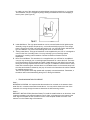
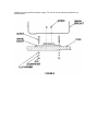
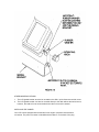
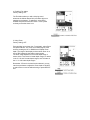
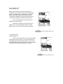
TRANSDUCER MOUNTING PROCEDURE
Humminbird’s high-speed transducer is supplied with your LCR. This transducer has been
designed to give good high speed readings on most all boat designs, including aluminum.
Please carefully consider the following before installing your transducer.
TRANSDUCER MOUNTING OPTIONS
A. Transom Mount- The Humminbird high speed transducer allows the transducer element to be
mounted below the bottom of the boat hull keeping the transducer out of turbulent water and
insuring good high speed operation. The transducer will absorb the blow of any obstruction
by rotating up out of the metal spring bracket without harming the transducer, or your boat.
The transducer can be re-engaged by simply rotating the transducer down and snapping it
back in place. (See Figure A)
B. Inside Hull Mount- The high speed transducer can be mounted inside the hull (without pivot
assembly) using the proper two-part epoxy, such as Humminbird’s epoxy kit. Even though
there is some loss of signal in shooting through the hull, your LCR will perform well with this
type of installation. You cannot shoot through the hull of an aluminum boat.
C. Trolling motor Mount- This type of transducer is not supplied with your LCR. It is designed to
mount on the foot of a trolling motor. You may exchange your un-used high speed
transducer for a trolling motor transducer. Call the Humminbird Customer Service
Department.
D. Bronz Thru-Hull Mount- This transducer is not supplied with your LCR but for an additional
cost you may exchange your un-used high speed transducer for a bronz thru-hull. The bronz
thru-hull transducer has a threaded stem which installs through a hole drilled in the boat hull,
leaving the housing exposed under the boat. This type of installation must be used for many
boats with in-board engines, because there is no suitable location on the transom away from
the noise and turbulence created by the prop. A bronz thru-hull transducer should be installed
by qualified personnel only.
The LCR will operate well at high speeds with a properly mounted transducer. Remember, a
transducer will not work transmitting through air or through air bubbles.
1.
TRANSOM MOUNTING PROCEDURE
Step 1.
MOUNTING LOCATION- It is important that the transducer be mounted on the transom where
water flow is in constant contact with the transducer. You may wish to observe the rear of the
boat while it is moving through the water to determine the best mounting location.
Step 2.
BRACKET INSTALLATION (Aluminum Boats)- To install the metal bracket on an aluminum boat
locate the template on the transom between rows of rivets, or ribs that are on the bottom of the
boat. Align the template so that the bottom corner of the template nearest the center of the
transom is on the bottom edge of the transom.
Once the location is determined mark and drill three 7/64” dia.. holes noted on the template.
Attach the metal bracket using three #10 self threading screws supplied. Be sure to align holes in
the center of the
Bracket slots. On some aluminum boats it may be necessary to use a wood back-up plate. It is
important to use a silicone sealant between the screwhead and bracket in order to prevent
leaking. (See Figure C)
Step 2.
BRACKET INSTALLATION (Fiberglass Boats)- If your boat has a stepped transom located
below and under the main transom, the compact transducer design allows mounting in this area.
This mounting location is recommended for good reading at very high speeds. (See Figure D)
To install the metal bracket on a fiberglass boat, locate the template on the transom in the same
manner as for an aluminum boat. (See Figure C)
NOTE: On boats with more than 15 degree deadrise angle it may be necessary to mount the
transducer slightly off parallel with the water level. (See Figure E)
Mark and drill the three 9/64” dia. holes as shown on the template. Attach the metal bracket using
the three #10 self threading screws supplied. Be sure to align the holes so that they are centered
vertically in the three slots found in the bracket. It is important to use a silicone sealant between
the screwhead and bracket in order to prevent leaking.
Step 3.
TRANSDUCER PIVOT ASSEMBLY- Assemble the pivot to the transducer main body using the
two ¼”x5/8” allen head screws, two 3/8” tooth washers and two, ¼” square nuts. Make sure the
tooth washers are sandwiched between the transducer main body and the pivot. The square nuts
are trapped inside the pivot and will not rotate as the allen head screws are tightened.
HOWEVER, DO NOT TIGHTEN AT THIS POINT. (See Figure F)
Step 4
TRANSDUCER ASSEMBLY- Insert the transducer assembly into the metal bracket from the
bottom. Push up until the holes in the plastic pivot align with the uppermost holes in the bracket.
Slide the O-ring on to the headed pin and insert it through the two parts. Assemble by screwing
the ¼”x3/8” allen head screw into the end of the pin and tighten. (See Figure G)
Step 5
ANGLE ALLIGHMENT- Set the transducer angle so that it is parallel with the bottom of the boat
hull. Once proper alignment is achieved, tighten the two allen head screws using the 5/32” allen
wrench provided. The screws are visible through the access holes on each side of the metal
bracket. Check to make sure the transducer main body is rigidly fastened to the pivot. (See
Figure H)
Step 6
CHECK POSITION OF TRANSDUCER- At this point, check to see that the bottom of the
transducer is a minimum of ¼” below the bottom of the transom. (However, as noted in STEP 2,
the top of the transducer cannot fall below the bottom of the transom). If it is not, remove the
transducer assembly from the metal bracket by removing the pin installed during STEP 3. Loosen
the metal bracket mounting screws, re-position the bracket utilizing it’s slotted holes, tighten and
re-assemble. It may be necessary to replace the silicone sealant after this adjustment is made.
NOTE: It may be necessary to make several high speed runs to adjust transducer either
UP/DOWN or to re-adjust the angle to achieve optimum results.
Step 7
CABLE CLAMPS- Install cable clamps as necessary by drilling a 1/8” dia. hole for the # 8 screw
supplied.
2. INSIDE HULL MOUNTING PROCEDURE
Warning: In order to achieve proper results with this type installation, it is important that the
transducer be mounted by someone familiar with the use of two part epoxy adhesives. For this
reason, Techsonic Industries, Inc. will not be responsible for any damage due to the mounting of
your transducer in this manner.
NOTE: An Epoxy Kit (Part N. EPK) is available from Humminbird. This Epoxy Kit has been
formulated for Inside Hull Transducer Installation.
1.
2.
3.
4.
5.
6.
Select as flat an area as possible near the aft end and center of boat where the hull is thin
and not double. If the bottom has a runner down the center of boat, select an area to one side
of the runner, but as close to the runner as possible.
Clean the inside of the boat with lacquer thinner in the area transducer is to be mounted.
Outside of boat in this area should also be cleaned. (Not with lacquer thinner).
Put approximately one inch of water in the bottom of the boat.
Put transducer in the water. The bottom of the transducer should be in a flat area and should
be in good contact with the bottom of the boat.
Operate the LCR with the boat operating at high speed. The transducer may have to be
moved in order to find an area where satisfactory operation is observed.
When an area is found that produces satisfactory operation, mark the location of the
transducer.
7.
Remove the water and transducer and clean the marked area and the bottom of the
transducer thoroughly.
8. Using the Humminbird Epoxy Kit or equivalent, mix an ample amount of epoxy without
causing it to bubble and pour it in the area the transducer is to be mounted. The puddle
should be larger than the bottom of the transducer.
9. Coat the bottom of the transducer with epoxy, then put it in the center of the puddle and push
down on the transducer while moving it around in a circular motion. This forces out any air
bubbles that may be trapped between the bottom of the transducer and the hull of the boat.
10. Let epoxy cure then the transducer is ready to operate. No water is now required in the
bottom of the boat and gas and oil that is spilled inside of the boat will not degrade
performance as it will if the transducer is placed only in water.
CAUTION: Do not use the silicone seal or any soft adhesive to bond the transducer to the
hull. This will reduce the sensitivity of the unit.
CAUTIONS
1. Occasionally the “eye“ of your transducer may become dirty from storage or from contact with
oils present in boats or marina environments. (Oil will cause the “eye” to lose the intimate
contact with the water which is necessary for efficient operation.) The “eye” may be cleaned
with liquid detergent.
2. Improper installation of the transducer can alter the efficiency and accuracy of the entire
system.
3. If your boat of transducer is out of the water for a period of time, it may take a short period of
time for the transducer to become thoroughly “wetted” when returned to the water. Also, reentry may cause turbulence, which will create air bubbles in the “eye” of the transducer. The
bubbles will disappear in a short time or can be removed by rubbing the transducer “eye” with
your fingers while the transducer is in the water.
4. If your instrument should fail to function, be sure to check all the electrical connections before
removing the transducer or calling a serviceman.
5. Inspect your transducer cable and make sure that it has not been cut or damaged to the point
where it will affect the performance of the transducer. A slight nick or cut, exposing the outer
cable, can be repaired by wrapping with electrical tape. A transducer can be damaged if the
inner cable and outer cable are allowed to make contact. Such a problem can sometimes be
corrected by properly splicing the coaxial cable. This should only be attempted by a qualified
service technician.
6. If your LCR is not working properly and you suspect the problem might be in your transducer,
we would recommend you borrow a unit from a friend and try it on your boat. If the symptoms
are the same, you can almost be certain that the problem is in the transducer.
INSTALLING THE LCR
The LCR should be mounted on a flat, solid surface for maximum stability. The low profile swivel
mount has four holes drilled in the base. It is recommended that all four holes be used.
Position the swivel base and drill four ¼” diameter holes. Note: The LCR hole pattern Is the same
as for all Humminbird flasher units. Use hardware provided to mount this base to the boat.
Next place the gimbal bracket on the swivel base and attach with four small machine screws,
provided.
Place the LCR in the gimbal mount and make certain the rubber washers provided are placed
between the unit and the gimbal bracket Important: Note which side of the gimbal faces forward.
(Slots on gimbal bracket go towards rear). Also, rubber washer must be located between the unit
and the gimbal bracket.
Install the mounting knobs and tighten snugly. The unit can now be swiveled and tilted to any
desired position.
OTHER MOUNTING OPTIONS
1.
2.
The LCR gimbal bracket can also be mounted on the SM-4, quick disconnect swivel mount.
The LCR gimbal bracket can also be mounted directly to the dash without the swivel mount,
however, this method is not recommended since the unit cannot be rotated.
INSTALLING THE CABLES
Your LCR comes equipped with Humminbird’s new Angle-Lock power and transducer
connectors. The power connector is identified with the letter P on the back of the plug.
It plugs into the outlet on the back of the unit marked “Power”. The transducer connector is
identified with the letter T and plugs into the outlet on the back of the unit marked “Transducer”.
Note: An adapter (AD-4) is available to allow use of an old waterproof (BNC) transducer with the
LCR, but be sure that the transducer is a 16degree. A 32-degree transducer cannot be used.
A 11/8” hole must be drilled to pull through the transducer connector. After drilling the hole, pull
the transducer connector up through the hole. If you are installing two units, both transducer
connectors can be pulled through this 1 1/8” inch hole. Next, push the power cable wires down
through the hole. A hole cover has been provided which will dress and hold the wires. Install the
hole cover after determining the necessary wire length from the hole.
The power cable has a red lead to the positive (+) post and the black lead to the negative (-) post.
Install a 1 amp fuse between the red cable and positive post of your 12-volt battery.
If a fuse panel is available, we recommend wiring the power cable into the fuse panel. Note: The
LCR must be fused separately from any other accessory.
Your Angle-Lock connectors can only be plugged in one way. Position the connector so the letter
P or T can be read and the 90 degree bend is pointed downward. Push the connector in as far as
it will go. Turn the positive locking ring as far as it will go clockwise until you feel it lock. Locking
ring as far as it will go clockwise until you feel it lock. Your connector is now locked into place.
Note: For easy access to the connectors, simply loosen the mounting knobs and tilt your LCR
forward. The connectors are now in full view and easy to plug or unplug.
INSTALLING THE ULTIMA
Before mounting the Ultima, gather the parts you need; Ultima, gimbal mounting bracket,
mounting hardware kit, power cable, and transducer cable. If the transducer cable is not long
enough for your installation, see "Accessories" earlier in this manual for information on the EC-6
10' extension cable.
Next, consider where to mount the Ultima_ The gimbal mount offers mounting capabilities
for the top of a shelf or the bulkhead (and lets you tilt the unit forward and backward for ease of
viewing and operation). To choose the best location, consider the following:
• The mounting surface should be adequately supported to protect the Ultima from excess wave
shock and vibration.
• The mounting area should allow at least 2" clearance at back, sides, and top of the unit for
connection, air flow, and ease of removal.
• Any VHF radio you have may incur some degree of interference with the depth sounder.
Humminbird depth sounders are designed to minimize this interference, although it is best to
route the transducer cable and antenna cable as far away from each other as possible, for
example, on opposite sides of the boat.
After you have determined the best location for your Ultima, proceed with the instructions on the
following page.
1. Set the gimbal mount on the mounting surface.
2. Mark lib" holes for the mounting screws.
3. At least 3" behind the bracket, mark a 3/4" hole to run the cables through.
4. Set the gimbal mount aside and drill the holes as marked.
S. Mount the bracket, using the mounting hardware supplied with your Ultima.
6. To connect the power cable to the 12-volt DC power source, wire the Ultima through your fuse
panel with a I -amp fuse (not included).
If your boat does not have a fuse panel, you can wire the power cable to the battery with an inline 1-amp fuse and fuse holder (not included) in the positive wire, as shown on the following
page. Do not connect directly to the battery without a fuse. Attach the black lead to the negative () terminal, and wire the red lead through the fuse to the positive (+) terminal.
Note: Do not use any power cable other than the one provided with your Ultima. However, you
may lengthen the cable with 18 gauge wire.
7. Pull the transducer, power, speed and temperature cables up through the 3/4" hole behind the
gimbal bracket, and connect them to the back of the Ultima. (The power cable is identified by a
"1" on the plug, the transducer cable by a "2", the speed cable by a "3", and the temperature
cable by a "4" on the plug).
8. Push any excess cable into the hole.
9. Mount the Ultima on the gimbal bracket by loosening the mounting knobs and slipping the unit
into the bracket. Be sure to keep the rubber washers between the bracket and the unit. Tighten
the knobs to hold the Ultima in viewing position.
TESTING THE INSTALLATION
After installing your Ultima, transducer, and cables, you should test the installation.
Testing should be performed on the water, since that is the only way to check your transducer's
performance.
With your boat at idle, press the POWER button until it "chirps" once to turn the unit on.
The Ultima performs a self-test on its electronics, then automatically selects the right depth range
and sensitivity level for conditions. Momentarily, you'll see the reading start to "march" across the
screen from right to left.
Increase your boat speed to ensure that you get a continuous bottom reading as the boat
moves. Your Ultima and its transducer are designed to operate at up to 120 kph. However, use
caution when operating any boat at high speed. (High-speed testing does not apply to portable
transducers with suction-cup mount)
If the Ultima performs well at idle or slow speeds, but the display is not continuous at
higher speeds, the transducer is not installed properly. Air bubbles or turbulence from the boat
hull are passing across the transducer face, blocking the transmitted signal. By following the
instructions in "Mounting the Transducer," you can make simple adjustments that should fix the
problem.
NOTE: If other problems occur, see "Troubleshooting" later in this manual for lips from the
Humminbird engineers. If you don't find the solution there, call our toll free Customer Service
Hotline.
USING THE ULTIMA
This section provides complete information on operating the Ultima through its front panel
controls. You are encouraged to read this information completely as you first learn to use the
Ultima. Doing so will ensure you make the most of its many features and functions.
The first part of this section explains the use of the built-in simulator, which you can use
to practice selecting functions through the front panel. The remaining instructions, which can be
followed while using the simulator or in actual operation, explain each function and are organized
according to the front panel layout.
USING THE BUILT-IN SIMULATOR
The Ultima includes a built-in simulator that helps you learn to use your new equipment.
The simulator displays a typical underwater scene, and lets you practice with the controls.
The unit must be turned off before you start the simulator. To activate it, press down and
hold the POWER button until a chirping sound begins. Release the button, and the built-in
simulator begins displaying a typical Ultima reading.
You can use the simulator to learn the functions explained in the following pages, just as
if you were getting actual on-the-water readings (but note that "Sensitivity" is disabled). To turn off
the simulator, turn off the unit by pressing the POWER button again.
Of course, the best way to learn the Ultima is with actual use, especially in familiar
waters. If you know what's below and see it on-screen, you'll quickly become an Ultima expert.
Operating the Ultima
WHAT YOU SEE ON-SCREEN
OPERATING THE ULTIMA
The Ultima offers several functions that you can adjust with the front
panel buttons. (Note that to select something with a button, you must press it
fully so that you hear a "chirp" sound).
You can get acquainted with these features by actual operation, or
when using the simulator.
POWER: Press this once to turn the Ultima on. Pressing it again turns the
Ulfma off. When the unit is off, keeping POWER pressed for about 2 seconds
starts the built-in simulator.
STOP: Press this to "freeze" the display so you can study it. Press it again to
restart the display movement.
SELECT: This button is used to access the following functions for further
adjustments:
• Sensitivity/Units
• Depth Range
• Bottom Alarm
• Fish Alarm
• Zoom
• Bottom Lock
• Fish ID
• Display Speed
• TripLog
To adjust any of these, press SELECT until the function you want appears. Each
function's display tells you how to use the arrow buttons and ONOFF for adjustment; when first
learning, you should also refer to the following instructions.
After you adjust any function, the display returns to its full-screen reading.
NOTE: While the Ultima remains on, he last function you select remains "active"-that is, you can
adjust it without having to press SELECT again. You can use this to simplify operations.
For example, if the bottom alarm was the last function used, you can readjust the alarm
by pressing one of the arrow buttons. Or if you often use Zoom, you can select it once, then
switch it on and off by simply pressing ON-OFF.
The following pages describe each function, in order of appearance as you first press
SELECT.
1. Selecting Sensitivity/Units;
Factory setting: +0/Meters
The Sensitivity/Units function has two uses: It lets
you adjust Ultima sensitivity and controls whether depth
measurement is in feet or meters.
The Ultima automatically increases or decreases its
sensitivity setting when water conditions change (as when
the bottom is stirred up). If you want to manually adjust
Sensitivity, select SENS and press the UP or DOWN arrow
button to adjust the automatic setting with a "+5" to "5"range. For example, if you set it at "+2", Sensitivity
remains 2 settings higher than the normal automatic setting.
An on-screen indicator at the bottom of the screen shows
the sensitivity setting when the menu is hidden.
Pressing the ON-OFF button when the SENS menu
is displayed switches the unit of depth measurement
between meters and feet.
2. Setting Depth Range;
Factory setting: On (Automatic)
When you turn the Ultima on, it finds the
bottom, sets the ideal depth range, and automatically
adjusts the depth range (to as much as 185 meters)
as the depth changes. In this "Auto Depth Range"
mode, the bottom is blacked-in for easy-tounderstand readings.
If you prefer, you can turn Auto Depth Range
off. Select DEPM RANGE, press ON-OFF, and adjust
the Depth Range with the UP or DOWN arrow key.
In this "Manual Depth Range" mode, the
bottom is not blacked in.This lets you see a "second
return," which is preferred by some fishermen because
the width of the second echo can indicate bottom
hardness.
3. Enabling Bottom Alarm;
Factory setting: OFF
The Bottom Alarm lets you specify the minimum
depth you want to maintain. To use it, select Bottom Alarm;
then, press the ON-OFF button to activate the alarm, and
the UP or DOWN arrow key to adjust the depth at which the
alarm will sound. An alarm symbol is displayed when this
function is on.
When Bottom Alarm is on, you'll hear a continuous
chirping sound when the bottom is shallower than you
defined. This is very handy for alerting you to shallow water
or helping you to maintain position over structure.
NOTE: The Ultima should not be used as a navigation aid to
prevent collision, grounding, boat damage or personal
injury.
4. Enabling Fish Alarm;
Factory setting: OFF
The Fish Alarm alerts you with a chirping sound
whenever the Ultima detects fish (or another object not
attached to the bottom). To activate it, select FISH
ALARM and press the ON-OFF button. A fish symbol
reminds you that the alarm is on.
5. Using Zoom;
Factory setting; OFF
Zoom provides an up-close view. To activate it, select Zoom
and press ON-OFF. The Zoom view initially begins at the
surface; pressing the UP or DOWN arrow adjusts Zoom
depth. The range of the display is shown when Zoom is on
and a "ZM" appears by the bottom range number.
The Zoom range depends on the current depth range: 3
meters in the 5 and 9 and 19 meter depth ranges, 5 meters
in the 37, 55 and 74 meter depth ranges, and 10 meters in
the 11 I to 185 meter depth ranges.
Remember: If Zoom is the last function selected, you can
use the arrow button to adjust the Zoom depth or ON-OFF
to switch Zoom on and off without having to press SELECT
first.
6. Using Bottom Lock;
Factory setting; OFF
Bottom Lock provides an up-close view like Zoom,
except that in this case the zoomed view automatically
moves up or down to stay on the bottom. To use this
feature, select BOTTOM LOCK and press ON-OFF.
The range of the display is shown when bottom lock is
on and a "BL" appears by the bottom range number.
This is an ideal feature for finding structure or
locating fish near the bottom.
Remember; If bottom Lock is the last function
selected, you can use the ON-OFF button to switch
Bottom Lock on and off without having to press select.
7. Selecting Fish ID;
Factory Netting: On
When you turn the Ultima on, the unit automatically
sets Fish ID to the On position. To turn the ID feature off,
and display fish with pixels instead of the ID icons, press
the ON-OFF button while within the Fish ID menu. Pressing
the ONOFF button again reactivates the ID function.
8. Setting Display Speed;
Factory setting: Maximum
The Ultima display is "updated" (advances across the
screen) as you move through the water. The speed at which
the display is updated depends on the Display Speed setting.
To adjust it, select DISPLAY SPEED, and press the UP arrow
for a faster setting or the DOWN arrow for a slower setting.
In general, higher Display Speed settings provide
faster updates, while slower Display Speeds provide more
detailed information.
9. Using TripLog
Factory Setting: Off
The Ultima TripLog provides a full screen of
information on current conditions for elapsed time
distance and speed. To display it, select TRIPLOG and
press ON-OFF.
Further information is given on the next page.
All log information is continuously updated as
long the Ultima remains powered on. if you want to reset
Average Speed, Elapsed Time, and Elapsed Distance,
press the STOP button.
Pressing ON-OFF exits the Trip Log and returns
you to normal operation.
Note: TripLog requires the proper input from the temp
and speed accessories on the transom of the boat.
Maintenance
Your Humminbird Ultima is designed to give you years of trouble-free operation with
virtually no maintenance. Follow the simple procedures below to ensure that you Ultima continues
to deliver top performance:
If the unit comes in contact with salt spray, simply wipe the affected surfaces with a cloth
dampened in fresh water.
When cleaning the LCD screen, use a chamois and non-abrasive cleaner such as
WindexO. Do not wipe while dirt or grit is on the screen. Be careful to avoid scratching the
screen.
The transducer face may become dirty from storage or contact with marine environment
oil. Oil will cause the face to lose the water contact it needs to maintain efficient operation. Simply
clean the face with liquid detergent.
If your boat is out of the water for a long time, it may take a while for the transducer to
become thoroughly "wetted" when returned to the water. Also, the turbulence of re-entry may
cause air bubbles to form on the transducer face. The bubbles will quickly disappear, or can be
removed by rubbing the transducer with the fingers while the transducer is in the water.
Never leave the Ultima in a closed car or trunk, especially in extreme temperatures. Do
not attempt to repair the Ultima yourself. Repairs should be performed only authorized
Humminbird technicians.