1
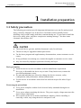
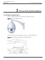
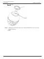
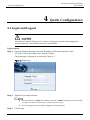
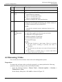
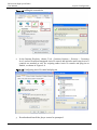
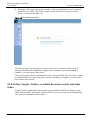
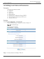
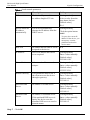
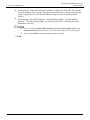
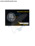
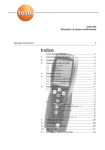
。 2 Mega Pixel IR Network High Speed Dome User Manual Issue V1.3 Date 2013-5-21 IR Network High Speed Dome User Manual About this Document About this Document Purpose This document is a user manual for IR Network High Speed Dome. Including the product features, hardware installation, network access, network configuration, technical specification and troubleshooting. Intended Audience This document is intended for: Technical support engineers. Maintenance engineer. Symbol conventions The symbols may be founded in this document are defined as followed: Symbol Description Alerts you to a high risk hazard that could, if not avoided. Alerts you to a medium or low risk hazard that could, if not avoided, result in moderate or minor injury. Alerts you to a potentially hazardous situation that could, if not avoided, result in equipment damage, data loss, performance deterioration, or unanticipated results. Provides a tip that may help you solve a problem or save time. Provides additional information to emphasize or supplement important points in the main text. Special notices When using video surveillance products, comply with applicable statutory and regulatory requirement to enable and maintain legal surveillance devices. It is illegal for a company or person to install surveillance devices in an office to monitor employees outside the scope of local law, or to use surveillance devices to invade other people’s privacy with illegal purposes. i Issue V1.3 (2013-5-21) IR Network High Speed Dome User Manual Contents Contents About this Document .................................................................................................. i Contents ........................................................................................................................ ii 1 Installation preparation .......................................................................................... 1 1.1 Safety precaution ............................................................................................................ 1 1.2 Checking the Installation Environment .......................................................................... 3 1.3 Network Plan .................................................................................................................. 3 2 Device Port and Description .................................................................................. 4 2.1 Product Appearance........................................................................................................ 4 2.2 Features .......................................................................................................................... 7 3 Hardware Installation ............................................................................................. 9 3.1 Preparing Installation Tools ............................................................................................ 9 3.2 Installing a Dome Camera ............................................................................................ 10 4 Quick Configuration ............................................................................................. 17 4.1 Login and Logout ......................................................................................................... 17 4.2 Main page layout .......................................................................................................... 18 4.3 Browsing Video ............................................................................................................ 19 4.4 Setting Local Network Parameters ............................................................................... 23 5 Technical Specification......................................................................................... 26 5.1 IRHigh Speed Dome technical parameters ................................................................... 26 6 Troubleshooting..................................................................................................... 31 7 Lightning Proof and Surge Signal Proof ........................................................... 32 Issue V1.3 (2013-5-21) ii IR Network High Speed Dome User Manual 1 Installation preparation 1 Installation preparation 1.1 Safety precaution The following precautions provide important information to prevent fire and personal injury caused by improper use of the device. Read this section carefully before installing a device and comply with these cautions during use. If you want to install the device in a public place, provide a conspicuous warning message “You have enter electronic surveillance area”. The actual device governs, and this document is only for reference. The device may be upgraded without prior notice. For the latest program and supplementary documentation, contact customer service center. If any problems occur during use, contact the supplier or customer service center. Any loss caused by improper operation is born by the buyer. Basic precaution Install the device in strict accordance with the manufacture requirement. Never try to dissemble the device on you own. If any fault occurs, contact the specified maintenance center. No unit and individual are allowed to change the device structure, safety configuration, and performance without authorization. Use the device in accordance with relate law and with respect for other’s legal rights. Power supply precautions Use a power complies with the local electrical safety standards during device installation. Use a power adapter matching this device. The power supply voltage must meet the input voltage requirement. Never power on the device before installation completes. Before installing or removing a cable, stop using the device and power it off. 1 Issue V1.3 (2013-5-21) IR Network High Speed Dome User Manual 1 Installation preparation Verify that a proper power supply is used before running the device. Keep the power plug to be clean and dry to prevent electric shock or other risks. Precaution For Use Avoid heavy weight, violent vibration, soaking during transport, store, and installation; otherwise, the device may be damaged. Any damage caused by improper transport of the assembled device during delivery from or sending back to the manufacture for repair is out of the warranties. Never install the device upside down. Hold the camera core carefully. Never tightly press any structural parts; otherwise, mechanical breakdown may occur. Never dissemble the device to repair it. The device must be checked and repaired by professional maintenance. Never scratch or abrade the device surface, otherwise, the paint that is drops down may cause allergy or device damage. For example, if it drops into the host, electrical malfunction may occur. If any exception occur, for example, smoke is blown out of the device, the device sounds abnormally, or peculiar smell is found, stop using the device, power it off, and remove all the cables(such as the power cables and networking cable) connected to the device. If the device is faulty, contact the specified maintenance center for repair. Clean precautions Before cleaning the device, stop using the device and power it off, and then remove all cables (such as the power cord and networking cable) connected to the device. Use a soft and dry cloth to clean the device. If there is any dirt that is difficult to clean, place a few drops of mild detergent on a soft and clean cloth before cleaning. After the dirt is removed, dry the device with a cloth. Never use any volatile solvents (such as the alcohol, benzene, and thinner) or strong and abrasive alkaline detergent; otherwise the device surface may be damaged or the device performance may be reduced. Environment Precautions Never allow any water or other liquid to flow into the device. If any liquid flows into device by accident, power the device off, and remove all the cables (such as the power cord and network cable) connected to the device. Avoid heavy weight, violent vibration, soaking during transport, storage, and installation; otherwise, the device may be damaged. Install the device at a place far away from the heat source or ignition source, such as an electric heater or lighted candle. Never install or use the device in places where flammable or explosive material are saved or in use. Issue V1.3 (2013-5-21) 2 IR Network High Speed Dome User Manual 1 Installation preparation Personnel precautions The device-related installation and maintenance can be only be performed by professional technical engineers or specific installation personnel. 1.2 Checking the Installation Environment Before installing the device, check the installation environment according to Table 1-1. Table 1-1 Installation environment check items Check Item Standard Moisture-r esistant The relative environment humidity must be in the range from 5% to 95%. If the humidity is higher than 95%, a dehumidifier must be installed, such as an air conditioner with the dehumidification function or a dedicated dehumidifier. In addition, water seepage, water dropping, and dew forming are not allowed. Dustproof If the office block is near the source of dust, such as the colliery, country road, and farm, aluminum alloy doors and windows of double layers must be installed for the offices, and anti-burglary and fireproofing doors must be installed for the equipment room. Lightproo f The device must be installed in the environment that is not shined by a strong light, delaying the aging of the device enclosure. 1.3 Network Plan 3 Issue V1.3 (2013-5-21) IR Network High Speed Dome User Manual 2 Device Port and Description 2 Device Port and Description 2.1 Product Appearance Figure 2-1 shows the appearance of an IR Network High Speed Dome. Figure 2-1 IR Network High Speed Dome Figure 2-2 shows the structure diagram of an IR Network High Speed Dome. Figure 2-2 Structure diagram of an IR Network High Speed Dome Issue V1.3 (2013-5-21) 4 IR Network High Speed Dome User Manual 2 Device Port and Description Figure 2-3 shows the multi-head cable used by a dome camera. Figure 2-3describes cores of the multi-head cable. Figure 2-3 Multi-head cable Table 2-1 cores of the multi-head cable No. Color Function Description 1 N/A Network port Connects to an external audio device such as a speaker. 2 N/A Video output port Sends analog video signals. You can connect the camera to a TV monitor through this port to view analog videos. 3 Red core Black core AC 24V power supply wire The red and black core supply power for the device, and supply power for the heater. Yellow core Alarm output channel 2 Orange core Alarm output channel 2 common terminal Seven channels of switching-value alarm input and two channels of switching-value alarm output. Grey core Alarm input channel 7 Blue core Alarm input channel 6 9 5 Issue V1.3 (2013-5-21) IR Network High Speed Dome User Manual No. 2 Device Port and Description Color Function Purple Alarm input channel 5 Brown core Alarm input channel 4 Green core Alarm input channel 3 Black red core Alarm input channel common terminal Black orange core Alarm input channel 1 Black grey core Alarm input channel 2 Black blue core Alarm output channel 1 common terminal Black purple core Alarm output channel 1 5 - Grounding wire N/A 6 Black brown core RS485 output (negative) Connects an external Pan Tilt Zoom (PTZ). Black green core RS485 output (positive) Black yellow core RS485 input (positive) Pink core RS485 input (negative) 7 Red-taped core Audio output Connects to an external audio device such as a speaker. 8 White taped core Audio input Receives analog audio signals from devices such as a sound pickup device. 4 Issue V1.3 (2013-5-21) Description 6 2 Device Port and Description IR Network High Speed Dome User Manual Figure 2-4 shows the location of SD card slot and reset button. Figure 2-4 The location of SD card slot and reset button 2.2 Features Network Features Support complete TCP/IP protocol suite. Support video, audio, and alarm data. Provides a built-in web browser and supports access using Internet explorer. Supports network data transmission and remote access. Support Point-to-Point protocol over Ethernet (PPPoE), Dynamic Host configuration protocol (DHCP), and Dynamic Domain Name System (DDNS). Protocols. Supports Power over Ethernet (POE) that complies with the IEEE802.3af standard. The IP camera can connect to a switch or router supporting the POE function to implement POE. Support remote upgrade and maintenance. 7 Issue V1.3 (2013-5-21) IR Network High Speed Dome User Manual 2 Device Port and Description Image Processing Features Support multiple steams. Single-stream model or dual-stream mode can be selected based on the site requirement. Encoding parameters for the main stream and sub stream be configured separately. Support dynamic stream parameters based on different image quality requirement. Support independent hardware compression and constant bit rate (CBR) and variable bit rate(VBR) Videos can be compressed using the Motion Joint Photographic Experts Group(MJPEG)or H.264 standards. The frame rate and image quality can be configured I/O Features Support bidirectional intercom and unidirectional broadcast. Support RS-485 serial port control and transparent channel transmission. Provides a 10/100 Mbits/s self-adaptive Ethernet port. Other Features Support the heartbeat function that allows the management host to learn the running status of the IP camera in real time. Support alarm input and output, motion detection alarm, and alarm linkage function. Supports level-based user rights management. Issue V1.3 (2013-5-21) 8 IR Network High Speed Dome User Manual 3 Hardware Installation 3 Hardware Installation 3.1 Preparing Installation Tools Table 3-1 show list installation tools that you must prepare. Table 3-1 Installation tools Tool Description Phillips screwdriver Claw hammer Hammer drill Level ruler Slotted screwdriver (camera accessory) Screw (camera accessory) Hexagon wrench (camera accessory) 9 Issue V1.3 (2013-5-21) IR Network High Speed Dome User Manual 3 Hardware Installation 3.2 Installing a Dome Camera 3.2.1 Installation Modes A dome camera supports wall-mounted and suspension installation modes. The following describes how to install a dome camera in wall-mounted mode. For details about other installation modes, see the Installation Guide. 3.2.2 Wall-Mounted installation Two kinds of bracket could be used. The following is steps for two installation ways. Wall-Mounted Installation I Step 1 Please make the mark based on bracket size for drilling the hole on the wall. And drill four φ8 holes over 60 mm depth. The bracket installing size is shown in the Figure 3-1. Figure 3-1 Bracket installing size Step 2 Insert four expansion bolts into the holes. Issue V1.3 (2013-5-21) 10 IR Network High Speed Dome User Manual 3 Hardware Installation Step 3 Attach the PTZ camera to the bracket and rotate the camera clockwise to align screw holes on the installing base of the camera and the bracket .Then tighten the three screws using to fix the bracket and camera, shown in the Figure 3-2. Figure 3-2 Fix the IPC onto the bracket Fa ste n in g scre w Step 4 Thread all the cables through the cable hole on the side of the bracket Step 5 Put on the bracket’s cover as shown in the Figure 3-3. Figure 3-3 Installing the cover plate of the bracket C o ve r p la te Th u mb scre w 11 Issue V1.3 (2013-5-21) IR Network High Speed Dome User Manual Step 6 3 Hardware Installation Mounting the PTZ dome camera to the wall, tighten the four screws on the bracket completely. ----end Wall-Mounted Installation II Step 1 Please make the mark based on bracket size for drilling the hole on the wall. And drill four φ8 holes over 60 mm depth. The bracket installing size is shown in the Figure 3-4. Figure 3-4 Bracket installing size 85 140 Step 2 Insert four expansion bolts into the holes. Step 3 Thread all the cables through the cable hole on the side of the bracket , show in the Figure 3-5. Issue V1.3 (2013-5-21) 12 3 Hardware Installation IR Network High Speed Dome User Manual Figure 3-5 Thread all cables through the bracket Step 4 Attach the PTZ camera to the bracket and rotate the camera clockwise to align screw holes on the installing base of the camera and the bracket .Then tighten the three screws using to fix the bracket and camera, shown in the Figure 3-6. Figure 3-6 Fix the PTZ camera and bracket together 13 Issue V1.3 (2013-5-21) IR Network High Speed Dome User Manual Step 5 3 Hardware Installation Mounting the PTZ dome camera to the wall , tighten the four screws on the bracket completely ----End 3.2.3 Suspension Installation Step 1 Please make the mark based on bracket size for drilling the hole on the wall. And drill four φ8 holes over 60 mm depth. The bracket installing size is shown in the Figure 3-7. Figure 3-7 Find the hole position and Make the mark for drilling the holes Step 2 Insert the expansion bolts into the holes. Step 3 Thread all cables through the cable hole on the side of the suspension bracket ,shown in the Figure 3-8. Issue V1.3 (2013-5-21) 14 3 Hardware Installation IR Network High Speed Dome User Manual Figure 3-8 Thread the cables through the cable hole on the bracket Step 4 15 Fix the suspension bracket and PTZ dome together and attach PTZ camera to the bracket with rotating the camera clockwise to align the screw holes on the PTZ camera base and suspension bracket .Then tighten the three screws fixing the PTZ dome and bracket , shown in the Figure 3-9. Issue V1.3 (2013-5-21) IR Network High Speed Dome User Manual 3 Hardware Installation Figure 3-9 Fixing Step 5 Mounting the PTZ dome camera to the ceiling and tighten the four screws on the bracket completely. ----End Issue V1.3 (2013-5-21) 16 IR Network High Speed Dome User Manual 4 Quick Configuration 4 Quick Configuration 4.1 Login and Logout You must use Internet Explorer 6 or a later version to access the web management system; otherwise, some functions may be unavailable. Login system Step 1 Open the Internet Explorer, enter the IP address of IP camera (default value: 192.168.0.120) in the address box, and press Enter. The login page is displayed, as shown in Figure 4-1 Figure 4-1 Login page Step 2 Step 3 17 Input the User and password. The default name is admin. The default password is admin. Change the password when you log in the system for first time to ensure system security. You can change the system display language on the login page. Click Login. Issue V1.3 (2013-5-21) IR Network High Speed Dome User Manual 4 Quick Configuration The main page is displayed. ----End logout To logout of system, click Sign out in the upper right corner of the main page, the login page is display after you log out of the system. 4.2 Main page layout On the main page, you can view real-time video, set parameter, Video parameter, Video control, PTZ control, PTZ Configure and log out of the system. Figure 4-2 is shown the main page layout. Figure 4-2 Main page layout Table 4-1 Elements on the main page N O. Element Description 1 Real-time video area Real-time videos are displayed in this area, You can also set sensor parameters. 2 Menu area You can choose a menu to set device parameters, including the device information, audio and video streams, alarm setting, and privacy mask function. 3 Video area Video parameters, such as the I frame interval, bit rate Issue V1.3 (2013-5-21) 18 IR Network High Speed Dome User Manual 4 Quick Configuration N O. Element Description type, bit rate, and quality, are display. 4 Video control area You can perform the following operation in this area: Switch between cameras. Start or stop playing Videos. Start or stop playing audio. Enable or disable the intercom function 5 PTZ control You can control the camera direction, zoom in or out, and change the focal length and aperture for a dome camera or a camera connected to an external PTZ. NOTE Currently the automatic aperture adjustment function is not support. 6 PTZ configuration area you can perform the following operation in this area: Add, delete, and invoke the presents and tacks. Adjust the PTZ rotation speed. Enable or disable 3D position. Set the direction to due north. Set the PTZ timer. NOTE PTZ timer function as a time trigger. When it is activated, the PTZ rotates according to presents and tracks as scheduled. The PTZ timer use the time set in camera. Ensure the time is correct. This function is available only to a camera with PTZ or camera connected to external PTZ. 4.3 Browsing Video User can browse the real-time video in the web management system. Preparation To ensure the real-time video can be play properly, you must perform the following operation when you log in to the web for the first time: 1. Open the Internet Explorer. Choose Tools > Internet options > Security > Trusted sites > Sites. In the display dialog box, click Add, as shown in Figure 4-3. 19 Issue V1.3 (2013-5-21) IR Network High Speed Dome User Manual 4 Quick Configuration Figure 4-3 Adding the a trusted site 2. In the Internet Explorer, choose Tool > Internet Options > Security > Customer level, and set Download unsigned ActiveX control and initialize and script ActiveX controls not marked as safe for scripting under ActiveX controls and plug-ins to Enable, as shown in Figure 4-4. Figure 4-4 Configuring ActiveX control and plug-ins 3. Download and install the player control as prompted. Issue V1.3 (2013-5-21) 20 4 Quick Configuration IR Network High Speed Dome User Manual The login page is display when the control is loaded. 4.3.1 Download the right control in the Internet Explorer Preparation User uses the Internet Explorer browse video. Real-time video page pop-ups the message “clicks to play live video with ActiveX control to reduce latency” as shown in Figure 4-5. Figure 4-5 Change the ActiveX Click the message, jump to download ActiveX control interface, once downloading is complete, you can watch more fluent video screen. Unable to display video picture, and need to download and install the control Preparation 21 User uses the IE Explorer browse video. Issue V1.3 (2013-5-21) IR Network High Speed Dome User Manual 4 Quick Configuration Real-time video page pop-up the message “click to download the latest version of Flash Play live video” and “click to play video with ActiveX control to reduce latency” as shown in Figure 4-6. Figure 4-6 Download control tips Click the message” click to play live video with ActiveX control to reduce latency”, jump download Adobe Flash Player Plugin control interface, once downloading is complete, you can watch video screen. Click the message “click to download the latest version of Flash Play live video”, jump to download ActiveX control interface, once downloading is complete, you can watch more fluent video screen. 4.3.2 In the Google, Firefox, or Safari browsers watch real-time video Google, Firefox, and Safari browsers only support Adobe Flash Player Plugin to play video. When Adobe Flash Plugin control version is too low, browser will automatically clew you to download the latest control. Issue V1.3 (2013-5-21) 22 4 Quick Configuration IR Network High Speed Dome User Manual 4.4 Setting Local Network Parameters Description Local network parameters include: IP protocol IP address Subnet mask Default gateway Dynamic Host Configuration Protocol (DHCP) Preferred Domain Name System (DNS) server Alternate DNS server Procedure Choose Device Configuration > Local Network. The Local Network page is displayed, as shown in Figure 4-7. Figure 4-7 Local Network page Step 4 23 Set the parameters according to Table 4-2. Issue V1.3 (2013-5-21) IR Network High Speed Dome User Manual 4 Quick Configuration Table 4-2 Local network parameters Step 5 Parameter Description Setting IP Protocol IPv4 is the IP protocol that uses an address length of 32 bits. [Setting method] Select a value from the drop-down list box. [Default value] IPv4 Device obtain an IP address automatically The device automatically obtains the IP address from the DHCP server. [Setting method] Click the option button. DHCP IP IP address that the DHCP server assigned to the device. N/A IP Address Device IP address that can be set as required. [Setting method] Enter a value manually. [Default value] 192.168.0.120 Subnet Mask Subnet mask of the network adapter. [Setting method] Enter a value manually. [Default value] 255.255.255.0 Default Gateway This parameter must be set if the client accesses the device through a gateway. [Setting method] Enter a value manually. [Default value] 192.168.0.1 Preferred DNS Server IP address of a DNS server. [Setting method] Enter a value manually. [Default value] 192.168.0.1 Alternate DNS Server IP address of a domain server. If the preferred DNS server is faulty, the device uses the alternate DNS server to resolve domain names. [Setting method] Enter a value manually. [Default value] 192.168.0.2 NOTE To query the current IP address of the device, you must query it on the platform based on the device name. Click OK. Issue V1.3 (2013-5-21) 24 4 Quick Configuration IR Network High Speed Dome User Manual If the message "Network Parameter Updated" is displayed, click OK. The system saves the settings. The message "Set network params success, Please login system again" is displayed. Use the new IP address to log in to the web management system. If the message "Invalid IP Address", "Invalid Subnet Mask", "Invalid default gateway", "Invalid primary DNS", or "Invalid space DNS" is displayed, set the parameters correctly. If you set only the Subnet Mask, Default Gateway, Preferred DNS Server, and Alternate DNS Server parameters, you do not need to log in to the system again. You can click Reset to set the parameters again if required. ----End 25 Issue V1.3 (2013-5-21) IR Network High Speed Dome User Manual 5 Technical Specification 5 Technical Specification 5.1 IRHigh Speed Dome technical parameters Table 5-1 shows the IR High Speed Dome technical parameters. Table 5-1 Technical parameters table Items parameters Module:FCB-CH6300 Module function Image sensor 1/2.8 Type Exmor CMOS Sensor Pixels 2 Mega Pixel resolution 1920×1080 Video system 1920×1080p/25fps;1920×1080p/30fps Synchronous internal Synchronous Len 4.7mm(wide) – 94mm(tele),F1.6 – F3.5 Minimum working distance 10mm(wide) 1000mm(tele) Focus Auto/manual Optical variable times 20x Digital zoom 12x N/A Horizontal viewing angle 55.4 degree(wide) – 2.9degree(tele) 58.16degree(wide) – 2.9degree(tele) S./N Ratio 50dB Minimum illumination ICR off:0.26Lux ICR on :0.005Lux Recommend working illumination 100Lux – 100000Lux BLC on/off Issue V1.3 (2013-5-21) Module;CMD-8100DN 4.7mm(wide) – 103mm(tele),F1.6 – F3.2 Auto/manual /push 22x ICR off:0.1Lux; ICR ON:0.002Lux 30Lux – 100000Lux N/A 26 IR Network High Speed Dome User Manual 5 Technical Specification Items Dome function 27 parameters Module:FCB-CH6300 Module;CMD-8100DN Iris Auto/manual Auto Electric shutter 1/1 – 1/10000 sec, have 22 level 1/25–1/10000 sec White balance mode Auto/automatic track/indoor/outdoor/man ual/sodium lamp ATW/PUSH Gain control Auto/manual, -3–28dB, have 16 level Auto 0dB – 28dB Wide-dynamic Auto/open/close On/off Nose suppression 6 level sharpness 16 level Horizontal range 360 Degree continuous Horizontal speed 0.01-120 degree/sec Vertical range 0-180 degree, auto rotation Vertical angle 0-93degree Vertical speed 0.01-120 degree/sec Grid indication support Direction support Present 255 Present speed 120 degree/sec Present position <0.5 degree Line scan 12. boundary can be set Cruise 12, each up to 32 present point Pattern 6, maximum 1000 command each and 5 minutes. Guard position Present/cruise/ scan/ track Timing run Timing can be set to run present position, cruise, pattern etc. Power memory support Alarm function 7 alarm input (switch type), 2 alarm output (support normally open and normally close) 0-100 Issue V1.3 (2013-5-21) IR Network High Speed Dome User Manual Items Network function Issue V1.3 (2013-5-21) 5 Technical Specification parameters Module:FCB-CH6300 Alarm linkage Present ,cruise, pattern, SD card store can trigger switch output 3D position Support Remote update Support PTZ Control IP platform control, also support 485 control 485 interface Full duplex 485 Protocol PELCO-D,PELCO-P, support self-adaption, protocol can be customized 485 Software address Support BNC BNC male,1.0Vp-p/75ohm, support PAL/NTSC Intelligent temperature power control Support Intelligent fan control support Audio input/output Linear audio, 1 output, one input Network interface RJ-45,10/100Base-T SD card 1 MICRO SD card interface, support 32GB MicroSD card Video coding H.264(ISO/IEC 14496-10) high/baseline profile Bit rate control CBR、VBR Image coding specification Support Multi-stream Support OSD Time, date, channel number, temperature, and channel name, user-defined. Audio compression SupportG.711,G.723.1/AMR(optical) Bidirectional talk Support Motion detection Support Heartbeat Support Module;CMD-8100DN 1920x1080p@30fps 28 IR Network High Speed Dome User Manual 5 Technical Specification Items Infrared function General specifica tion 29 parameters Module:FCB-CH6300 Alarm events and handing Can through the internal dynamic, external input, or plan trigger events, Picture can upload through Email and HTTP Network transmission Auto adaptive flow control technology WebServer Build-in Web Server, support through the browser to see the real-time video and configure the parameters Network protocol IPv4/v6、RTP/RTCP、TCP/UDP、HTTP、DHCP、 DNS、FTP、DDNS、PPPOE、SMTP safety Password protection, support multistage user and multiple management Infrared lamp mode Can manual or automatic control switch IR viewing distance 100 meters Wavelengths 850nm Open infrared lamp illumination lower 1-3Lux Close infrared lamp illumination over 7-10Lux Open delay time 1 sec Close delay time 60 sec Infrared lamp strength intelligent control support Power supply Power supply: AC 24V, 4A Power Maximum power: 60W Heater power: 20W Operator temperature and humidity -40℃ – 60℃,humidity <90% Heaters starts working 5℃(error:±5℃) Module;CMD-8100DN Issue V1.3 (2013-5-21) IR Network High Speed Dome User Manual Items parameters 5 Technical Specification Module:FCB-CH6300 Module;CMD-8100DN temperature Issue V1.3 (2013-5-21) Protection level IP66(outdoor), 6K lightning protection, anti-surge, anti-break Store environment -40-85℃ humidity 0-95% Bracket Can choose outdoor wall-mounted bracket, corner-mounted bracket, and indoor lifting bracket. Installation Wall, ceiling, corner mounted Weight(withou t the bracket) 5.7KG 30 IR Network High Speed Dome User Manual 6 Troubleshooting 6 Troubleshooting Table 6-1 describes the common faults and solutions Table 6-1 Common fault and solution Problems Possible Causes Remedies No action when power is switched on Power supply fault Replace Bad connection of the power Correct Transformer damaged Replace Abnormal self-check. Images with motor noise Mechanical failure Repair Camera inclined Reinstall Power supply not enough Replace Video signal fault Reinstall Bad connection of the video Press to connect well Camera damaged Replace RS485 bus bad connection Check the RS485 connection Dome ID setup is wrong Reselect Protocol setup is wrong Reset and Switch ON again Bad connection of the video Press to connect well Power supply not enough Replace Self check error Switch ON again Bad connection of control Press to connect well Bad control of matrix Switch ON again In manual state Use the control command to set the lens of dome into manual state. Address of IR Remote controller error Correct IR Remote controller no battery Change battery Normal self-check but no images Normal self-check but out of control Vague image Dome camera out of control Lens of Dome out of control Use IR Remote controller on DVR but out of control 31 Issue V1.3 (2013-5-21) IR Network High Speed Dome User Manual 7 Lightning Proof and Surge Signal Proof 7 Lightning Proof and Surge Signal Proof The product adopts TVS lightning proof technology to prevent from damage by lightning strike below 1500 W and impulse signals such as surge; but it is also necessary to abide by the following precautions to ensure electrical safety based on practical circumstances: Keep the communication cables at least 50 meters away from high voltage equipment or cables. Make outdoor cable laying-out under eaves as possible as you can. In open area shield cables in steel tube and conduct a single point ground to the tube. Trolley wire is forbidden in such circumstances. In strong thunderstorm or high faradic zone (such as high voltage transformer substation), extra strong lightning proof equipment must be installed. Take the building lightning proof requirements into account to design the lightning proof and grounding of outdoor equipment and cable laying-out in accordance with the national and industrial standards. The system must be grounded with equal potentials. The earth ground connection must satisfy the anti-interference and electrical safety requirements and must not be short connected with high voltage electricity net. When the system is grounded separately, the resistance of down conductor should be ≤ 4Ω and the sectional area of down conductor should be ≤25mm2 (refer to Figure E.1). Issue V1.3 (2013-5-21) 32 A Declaration on Hazardous Substances in Electronic Information Products IR Network High Speed Dome User Manual A Declaration on Hazardous Substances in Electronic Information Products Part Hazardous Substances Pb Hg Cd Cr6+ PBB PBDE Mechanic al part ○ ○ ○ ○ ○ ○ Board/cir cuit module ○ ○ ○ ○ ○ ○ Connector ○ ○ ○ ○ ○ ○ Support devices ○ ○ ○ ○ ○ ○ ○: Indicates that the concentration of the hazardous substance contained in all the homogeneous materials of this part is below the limit requirement of the SJ/T 11363−2006 standard. ×: Indicates that the concentration of the hazardous substance contained in all the homogeneous materials of this part is above the limit requirement. 01.BSM.11.0081401C 33 Issue V1.3 (2013-5-21)