1
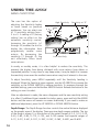
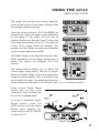
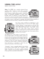
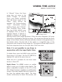
OPERATIONS
MANUAL
THANK YOU
THANK YOU FOR CHOOSING YOUR 425SX FISHFINDER, MADE BY
TECHSONIC INDUSTRIES, MANUFACTURER OF AMERICA’S #1 NAME IN
FISHFINDERS, HUMMINBIRD. HUMMINBIRD HAS BUILT ITS REPUTATION
BY DESIGNING AND MANUFACTURING TOP QUALITY, THOROUGHLY
RELIABLE MARINE EQUIPMENT. YOUR HUMMINBIRD PRODUCT IS
DESIGNED FOR TROUBLE-FREE USE IN EVEN THE HARSHEST MARINE
ENVIRONMENT.
IN THE UNLIKELY EVENT THAT YOUR HUMMINBIRD DOES REQUIRE
REPAIRS, WE OFFER AN EXCLUSIVE SERVICE GUARANTEE. COMPLETE
DETAILS ARE INCLUDED AT THE END OF THIS MANUAL.
WE ENCOURAGE YOU TO READ THIS OPERATIONS MANUAL CAREFULLY
IN ORDER TO GET FULL BENEFIT FROM ALL THE FEATURES AND USES OF
YOUR HUMMINBIRD PRODUCT.
WARNING! THIS DEVICE SHOULD NOT BE USED AS A
NAVIGATIONAL AID TO PREVENT COLLISION, GROUNDING,
BOAT DAMAGE, OR PERSONAL INJURY. WHEN THE BOAT IS
MOVING, WATER DEPTH MAY CHANGE TOO QUICKLY TO
ALLOW TIME FOR YOU TO REACT. ALWAYS OPERATE THE BOAT
AT VERY SLOW SPEEDS IF YOU SUSPECT SHALLOW WATER OR
SUBMERGED OBJECTS.
TABLE OF CONTENTS
Section 1: Installation preparation . . . . . . . . . . . . . .
Parts Supplied . . . . . . . . . . . . . . . . . . . . . . . . .
Accessories . . . . . . . . . . . . . . . . . . . . . . . . . . .
Installation Overview . . . . . . . . . . . . . . . . . . . .
Alternative Transducers and Mounting Methods.
Beginning Installation . . . . . . . . . . . . . . . . . . . .
.
.
.
.
.
.
.
.
.
.
.
.
.
.
.
.
.
.
.
.
.
.
.
.
.
.
.
.
.
.
2
2
2
2
4
5
Section 2: USING THE 425SX. . . . . . . . . . . . . . . . . . . . . . . 6
How Sonar Works . . . . . . . . . . . . . . . . . . . . . . . . . . . 6
Simulator Operation . . . . . . . . . . . . . . . . . . . . . . . . . . 6
What You See On Screen . . . . . . . . . . . . . . . . . . . 7–12
Control Functions . . . . . . . . . . . . . . . . . . . . . . . . 12–15
Menu Functions . . . . . . . . . . . . . . . . . . . . . . . . . 15–25
Section 3: ADVANCED FEATURES. . . . . . . . . . . . . . . . . . . 25
Using Diagnostic . . . . . . . . . . . . . . . . . . . . . . . . . . . 25
Section 5: MAINTENANCE . . . . . . . . . . . . . . . . . . . . . . . . 27
Maintenance and Troubleshooting . . . . . . . . . . . . 27–30
Specifications . . . . . . . . . . . . . . . . . . . . . . . . . . . . . . 31
INSTALLATION PREPARATION
PARTS SUPPLIED
PARTS SUPPLIED
Before installing your 425SX, please ensure the following parts are included in
the box:
•
•
•
•
•
425SX fishfinder
Transducer with 6m (20') of cable and mounting hardware kit
Mounting system and mounting hardware kit
2m (6' ) power cable
Publications kit
Note: The 425SX+ includes speed and temperature sensors with
appropriate hardware and instructions for installation.
If any of these items are missing contact your local dealer.
ACCESSORIES
Humminbird offers a wide assortment of accessories that complement and
expand the capability of your new 425SX. These accessories are designed with
the same high standards. The Humminbird Accessory catalog included with
your unit contains descriptions of the many accessories available and ordering
information. All Humminbird accessories are available through your full-service
Humminbird dealer.
INSTALLATION OVERVIEW
The 425SX consists of two primary components to install: the control head and
the transducer.
The control head contains the sonar transmit and receive circuitry, as well as the
user controls and display. It should be installed in a location that provides access
to the controls and visibility while in use. The control head mounts on a quick
disconnect mounting system that swivels and tilts, providing flexibility for
viewing from almost anywhere on the boat.
2
INSTALLATION PREPARATION
INSTALLATION OVERVIEW
The transducer converts electrical energy from the transmitter into mechanical
pulses or sound waves. The transducer also receives the reflected sound waves
and converts them back into electrical signals for display on the control head. It
should be installed in contact with the surface of the water in an area that has
smooth water flow - usually on the transom of the boat. There are several
mounting options for the transducer. Review
the following section to determine the
method that works for you and your boat.
Determining How to Mount the
Transducer
The 425SX includes a model XT-6-24
transducer. This transducer can be mounted
on the transom of the boat, or bonded to
the inside of a fiberglass hull boat.
The transom installation, which is the most
widely used, places the transducer on the
outside of the boat hull. This technique
Transom Mounted Transducer
produces the least signal loss, and provides a
way to adjust the transducer after
installation. The mounting hardware
included is designed to protect both
the boat and the transducer should the
boat strike debris in the water or when
trailering.
As an alternative to transom mounting,
it is possible on many fiberglass-hulled
boats to glue the transducer on the
inside of the boat hull. Since fiberglass
has similar sonar characteristics as
water, the sonar signal can pass
through the boat hull with minimal
loss. The hull of the boat must be single
layer construction (not double-hulled).
Also, any air trapped in the lamination
Inside the Hull Mounted Transducer
of the fiberglass would prevent the sonar
3
INSTALLATION PREPARATION
ALTERNATE TRANSDUCERS AND MOUNTING METHODS
signal from passing through.
Inside the hull installations require no holes to be drilled into the boat and
through experimentation, high-speed operation comparable to transom
mounting can be achieved. Two part, slow cure epoxy is required to glue the
transducer in place.
ALTERNATE TRANSDUCERS AND MOUNTING METHODS
The 425SX comes with everything necessary for installation and operation on
most boats. However, there are several situations which may require a different
type of transducer. Inboard boats, wood or metal hulls, and sail boats create
unique transducer mounting needs. Alternate transducers and mounting
methods are detailed below.
Portable Mounting
The standard transducer can be adapted for
portable installations using part number MHX-PT2.
This accessory adapts your transducer to a suction
cup mount for temporary installation on the boat
hull or other surface.
Trolling Motor Mounting
The standard transducer can also be adapted to
mount on most trolling motors using part number
AD-STM-7. This accessory includes a bracket and
hose clamp that allows mounting the transducer to
the body of most trolling motors.
TRANSDUCER EXCHANGE
Other transducers are available as replacements for the standard transducer.
You may exchange your new and unassembled transducer for another type by
returning it to the address listed in Customer Support. Some transducers may
have additional costs. Refer to the Accessory catalog or call Customer Support
for information.
4
INSTALLATION PREPARATION
BEGINNING INSTALLATION
BEGINNING INSTALLATION
Now that you have determined the transducer mounting method, you can
begin installation of the 425SX. The fold out installation guide included
provides detailed step by step instructions for installation of the control head
and transducer. For transom mount transducer installations, you will need the
mounting template at the back of this manual.
In addition to the parts included you need the following for installation and
operation:
•
•
•
•
•
•
•
•
•
A powered hand drill and various drill bits
Phillips and flat-head screw drivers
A ruler or measuring tape
Pen or pencil
12 volt power source (your boat’s battery)
A 1-amp fuse
A fuse holder (if you are wiring directly to the boat’s battery)
Silicone sealant (for sealing drilled holes)
2-part, slow-cure epoxy (for inside the hull transducer installations)
Note: If you have purchased the 425SX+ you will have in addition
to the parts and instructions above:
• Speed and Temperature sensors
• Instructions for installing speed and temperature sensors
• Appropriate hardware to mount sensors
5
USING THE 425SX
HOW SONAR WORKS
HOW SONAR WORKS
Your Humminbird unit uses sonar to
locate and define underwater objects,
define the bottom terrain, as well as
determine distance.
Sonar technology is based on sound
waves. Your Humminbird unit sends out
a sound wave signal. With this signal it
determines distance by measuring the
time between the transmission of the
sound wave and when the sound wave
is reflected off an object. Your
Humminbird uses the reflected signal to
interpret location, size and composition of an object.
Sonar is very fast. A sound wave can travel from the surface to a depth of 70m
(240') and back again in less than ¹⁄₄ of a second. It is unlikely that your boat
can "outrun" this sonar signal.
The 425SX is a 200 kHz, single-beam fishfinder. The 200 kHz frequency
provides excellent sonar resolution (the ability to distinguish small returns or
returns which are close to the bottom), while providing depth capabilities to
185m (600’). The shape of the sonar beam is symmetrical and covers an area
of approximately 24 degrees side to side and front to rear.
Actual depth capability depends on factors such as bottom hardness, water
conditions, and transducer installation. Units will typically read to deeper
depths in fresh water than in salt water.
SIMULATOR OPERATION
The 425SX contains a simulator that allows you to use the unit as if you are on the
water. The simulator is invaluable for learning how to operate the 425SX.
There are two ways to start the simulator. If the unit is powered off, press and hold
the POWER button for approximately three seconds until you hear a continuous chirp.
6
USING THE 425SX
SIMULATOR OPERATION
The simulator can also be started by selecting
the Simulator option on the start-up screen
after you power-up the unit. When this
screen is shown, simply press the DOWN
ARROW until “Simulator” is highlighted.
When the screen times out, the unit will be
in simulator mode.
When in simulator operation, the 425SX responds to control inputs as if it is in
actual operation, so feel free to experiment, or to customize the unit for your
particular operation.
To exit Simulator mode, power the unit off.
FEATURE MEMORY
If your 425SX is installed with a transducer connected, any changes you make
to the set-up or User Options (see Control Functions) while in Simulator are
retained in the unit’s memory. This allows you to use simulator to experiment
with the various set-up options, and retain your selected settings for normal
operation.
If you are using the 425SX in Simulator when no transducer is connected, any
selected options are lost when the unit is powered off. The 425SX will return
to Factory Settings, or options selected when last used with a transducer, if no
transducer is connected.
IMPORTANT: A transducer must be connected to the 425SX in
order to retain user settings selected when in simulator mode. If
no transducer is detected, the unit defaults to pre-selected
options when powered off.
What You See On-Screen
Your 425SX uses a 160 x 160 matrix FSTN LCD display. This display provides
outstanding viewability in all light conditions over a wide range of
temperatures.
7
USING THE 425SX
WHAT YOU SEE ON-SCREEN
At initial power-up, the 425SX uses settings that were set at the factory. After
initial use, the 425SX will remember the settings you enter.
There are several elements on-screen that are common to all modes of
operation.
Figure A
Temperature/Speed.
The
initial screen layout takes one
of two basic forms depending
on whether the optional
Temp/Speed accessory is
installed. Figure A shows the
default view when the
Temp/Speed accessory is
installed. Figure B shows the
default view when the
Temp/Speed accessory is not
installed.
Depth. The digital depth
number shows the water
depth directly beneath the
transducer location.
Depth Range. The depth range
is shown to the right of the screen.
The upper number is 0 indicating
the surface of the water. The lower
number is one of the nine depth
ranges available that best match
the depth of the water. As the
depth of the water changes, the
range changes as necessary in
order to retain a bottom
representation on-screen.
8
6
Figure B
Bottom Depiction
Water Depth
Zero Line
Depth Range
USING THE 425SX
WHAT YOU SEE ON-SCREEN
When in Auto mode, the horizontal line at the top of the screen is the “zero
line,” representing the surface of the water. Occasionally there is a gap in this
line. This gap indicates the unit is updating the display even if the bottom is not
visible on-screen, or if the bottom information is not changing.
New sonar information appears on the right side of the graphic area of the
display and moves to the left as new information is displayed. The 425SX
automatically selects the appropriate depth range to show the depth of water
beneath the transducer. This range is selected so the bottom representation is
typically shown about ²⁄₃ down the display.
Bottom. The graphic depiction of the bottom provides the user with an
effective tool for understanding the composition of the bottom. The FSTN type
display uses 4 discrete levels of gray to indicate the intensity of the returned
sonar signal. The 425SX can display even the smallest sonar returns with light
gray pixels. Larger returns are displayed with darker shades of gray. If the
bottom is hard and smooth, the bottom depiction is narrow and dense. If the
bottom is soft mud or sand, the depiction will be thick and less dense. This
indicates that much of the signal is absorbed by the soft bottom. If the bottom
is rocky or rugged in composition, the depiction is of varying density and
textured in appearance.
Wave action also affects the bottom
depiction. The information drawn is
a distance measurement, so if the
boat is moving up and down over
flat bottom, the bottom depiction
often appears in regular variations
that match wave timing.
Structure. Structure is defined as
any object physically attached to the
bottom. The sonar configuration of
the 425SX is optimized to give the
most accurate depiction of bottom
structure possible. Grass, trees,
stumps, wrecks or other debris are
accurately displayed, however the
Surface Clutter
Rocky Bottom
m
Hard Bottom Soft Bottom
9
USING THE 425SX
WHAT YOU SEE ON SCREEN
depiction of these objects varies with boat speed and direction. The best way to
learn to interpret structure is to operate the 425SX over a variety of known
conditions and experiment with user functions to best represent those
conditions on-screen.
Surface Clutter. Surface clutter is the layer of water near the surface that is rich
in algae and other growth, and often is aerated by wind or wave action. This
area of water interferes with sonar transmission and often appears on-screen as
regular clusters of individual dots near the “0” line.
Thermoclines. Thermoclines are sharp differences in water temperature. These
are easily identified by the continuous nature of the return.
Second Returns. When a
sonar signal is reflected off the
bottom back to the transducer,
there is often enough energy
left in the signal to be reflected
off the surface of the water
back to the bottom a second
time. Second returns appear as
a slightly weaker bottom
representation exactly twice the
depth of the primary bottom
return. The second return is
most likely to occur in shallow
water and in areas of relatively
hard bottom.
Thermocline
Second Return
Fish Arches. With Fish ID off, schools of bait fish as well as individual fish
are clearly visible on the 425SX display. Bait fish appear as "clouds" having
different shapes and sizes depending on the number of fish and boat
speed. Individual fish appear as smaller black and gray lines often
appearing as a "fish arch." A fish arch forms as the boat moves over the
fish. Due to the transducer beam angle the distance to the fish decreases
as it moves into the beam, and then increases as it moves out. When the
window graphs this distance change, an arch appears. The true depth of
the fish is the top of the arch when the boat is directly over the fish. Boat
10
USING THE 425SX
WHAT YOU SEE ON SCREEN
speed and movement of the fish greatly affect
the shape of the arch. When moving slowly, a
fish creates an elongated arch. With the boat
moving fast the arch appears shorter. A partial
arch forms when the fish does not move through
the entire cone angle.
Fish Arch Diagram
The 425SX displays structure such as submerged grass, brush, trees and
wrecks on the bottom. Structure can be distinguished by comparing the
area just above and below the main bottom return. Usually structure shows
as areas of dark to light gray on top of a dark bottom contour. The
appearance of structure is greatly affected by boat speed and direction; to
repeat the same image it is often necessary to travel the same speed and
direction over the location where the structure was originally located.
The 425SX is also capable of showing layers of water having different
temperatures. These temperature differences, called thermoclines, appear at
different depths, depending on current conditions. A thermocline typically
appears as a continuous band of light gray moving across the display at the
same depth. Thermoclines always appear above the bottom.
It is important to remember that sonar cannot distinguish between a fish
and some other object suspended in the water. Regardless of the object the
sonar detects, each could be drawn as an arch.
Fish ID. The 425SX uses
advanced signal processing
to further evaluate any
sonar return between the
surface and the bottom. For
instance, a small school of
bait fish usually appears as a
dense cluster of individual
dots. If the return meets
certain additional criteria, a
fish symbol will be assigned.
There are three different size
fish symbols used to indicate
ID+ Fish Depth
11
USING THE 425SX
CONTROL FUNCTIONS
the intensity of the sonar return. While signal intensity is a good indicator of
relative fish size, different species of fish have different sonar characteristics, so
it is not always possible to distinguish fish size between varying species. The
signal intensity is "normalized" for depth so that a small fish close to the boat
does not appear as a large fish symbol.
ID+ adds an additional piece of information to help the user locate fish. On selected
fish symbols, the digital depth of the designated fish is drawn to help locate the fish
vertically. This is especially helpful in setting bait depths or for downrigger
operation.
CONTROL FUNCTIONS
The 425SX uses a simple six button keypad for all user input. Press any button
and an audible “chirp” confirms the control input. If a button has no function or
is inappropriate for the situation, an audible “error” is heard. The unit sounds
multiple chirps.
Power. The Power button powers the 425SX up for normal operation. When the
unit is on, POWER turns the unit off. POWER can also be used to go directly into
Simulator mode. To enter simulator, with the unit powered off,
press and hold POWER for several seconds until a continuous chirp
is heard.
Light. LIGHT controls the unit’s display backlight. With the unit
powered on, press LIGHT once to turn the backlight on “low.”
Press LIGHT a second time to turn the backlight on “medium,” a
third time to turn the backlight on “high”, and a fourth time to
turn the backlight off. The backlight is very effective for low-light
and nighttime operation. When the backlight is on, the 425SX will
consume more power than with the backlight off. This is
important when using the 425SX in a portable configuration
powered by a separate battery, or when powering the unit from a
trolling motor battery.
12
USING THE 425SX
CONTROL FUNCTIONS
When powering the unit from a battery such as in portable
applications, you can prolong the battery life by using the
backlight at a minimum.
The three lower buttons, MENU, UP ARROW and DOWN ARROW work together
to control the 425SX menu-controlled user functions.
2D View
View. VIEW selects one of
several screen configurations or
“views” possible depending on
the transducer in use. When
using the standard transducer,
without
the
optional
speed/temp sensor connected,
the VIEW button toggles the
display between the full-screen
2D View and the Large Digital
Readout View.
The 2D View is the default view,
and the view which is first seen
at power-up. Pressing VIEW
again will select the Large
Digital Readout View, which
increases the size of key digital
information so that it can be
viewed from a great distance.
Normal 2D information is
displayed on the right side of
the display. Pressing VIEW again
will toggle the display back to
the 2D view.
6
Large Digit View
When using the standard
transducer, with the optional speed/temp sensor connected, the VIEW button
toggles the display between the full-screen 2D View, the Chart View and the
Large Digital Readout View.
13
USING THE 425SX
CONTROL FUNCTIONS
Chart View
The Chart View, shows only the
digital depth readout, leaving
more screen area for fish
location and bottom depiction.
Menu. MENU displays a menu
on-screen for adjustment. In
normal operation, pressing
MENU
repeatedly
cycles
through all available menus. A
menu remains on-screen for
several seconds, and can be
adjusted by using the ARROW
keys. If no adjustment is made in the allotted
time, the menu disappears. If you want the menu
to remain on-screen longer press and hold
MENU—the menu will remain on-screen
indefinitely. Once you release the menu button,
the screen will time out. Once a menu times out,
it is still considered the active menu. Press MENU
to bring up the last menu used.
Menu
Arrow Keys. The UP ARROW and DOWN ARROW make adjustments to menu
functions. On the left side of every menu there are UP ARROW and DOWN
ARROW symbols. The symbols indicate which ARROW button has a function in
a particular situation. Either one or both ARROW buttons can be used to adjust
the menu function. A hollow ARROW symbol means the corresponding ARROW
button has no function. Pressing that button will result in no adjustment and the
“error” audible will be heard. A solid ARROW symbol means the corresponding
ARROW button can be used to affect the menu adjustment.
Abbreviated Menu. The ARROW buttons often can be
used when no menu is on-screen. In these situations,
pressing the ARROW button affects the function of the
active (last-used) menu. This is a short-cut to menu
Abbreviated Menu
operation. An abbreviated menu appears on-screen while
the adjustment is made and times out. A frequently used menu can be
adjusted very quickly using this technique.
14
USING THE 425SX
MENU FUNCTIONS
After an adjustment is made to a menu function, the menu times out after a few
seconds and the unit returns to normal operation.
Menu Layout. All menus use the same basic layout. The heading at the top
describes the menu function. The UP ARROW and DOWN ARROW symbols to
the left of the menu indicate which buttons are available for adjustment. In
menus that have several possible settings, a range of adjustment indicator shows
the total range available and the current setting.
Within the menu are the options available. The selected option or current
setting is highlighted in the black box. If no adjustment is made, this is the
selected setting. Press an ARROW button while the menu is displayed to select
another option.
Several of the menus are multi-step. In some situations if an adjustment is
made, additional options become available for further adjustment. Examples of
these multi-step menus are Depth Range, Depth Alarm and Zoom. See the
detailed description of each function for further explanation.
Menu Functions
Heading
Up Arrow Option
Down Arrow Option
Arrow Symbols
Selected Setting
Range of Adjustment Indicator
Sensitivity. The Sensitivity function controls the sensitivity of the sonar
receiver. The 425SX automatically adjusts the level of
receiver sensitivity based on a number of factors
including the depth of the water and the level of
noise present. Noise can be caused by other
electronic devices, engines, trolling motors, propeller
cavitation and hydrodynamic flow among others.
15
USING THE 425SX
MENU FUNCTIONS
The user has the option of
adjusting the Sensitivity higher
or lower based on personal
preference. You can select one
of 11 sensitivity settings from 5 to +5. A setting of 0 (factory
setting) has no effect on the
automatic sensitivity control.
Increasing the sensitivity (+1
through +5) enables the unit to
display the information from
progressively smaller sonar
returns. By decreasing the
sensitivity (-1 through -5), the
unit effectively filters small
sonar returns.
High Sensitivity
Sensitivity at “0”
Low Sensitivity
In murky or muddy water, it is often helpful to reduce the sensitivity. This
prevents the display from being cluttered with sonar returns from debris or
suspended particles. In very clear or very deep water, it may be helpful to increase
the sensitivity since even the smallest sonar return may be of interest to the user.
To adjust Sensitivity, press MENU repeatedly until the Sensitivity heading is
displayed. When the Sensitivity menu appears, use the UP ARROW to increase the
sensitivity, or the DOWN ARROW to reduce sensitivity. To sequence through the
available settings, press and hold either ARROW button. Release the button at the
setting you want to select.
After an adjustment is made, the menu disappears and the new sensitivity setting
is in affect. If additional time is needed to study a menu, press and hold the MENU
button and the menu will remain on-screen indefinitely. If you need to make an
additional adjustment, press the UP ARROW or DOWN ARROW button.
Depth Range. The Depth Range function controls the vertical distance displayed
on the graphic area of the display. There are nine depth ranges available. The top
of the range is always 0, or the surface of the water. Ranges of 0–5, 0–10, 0–20,
0–40, 0–60, 0–80, 0–110, 0–150, and 0–185 metres and imperial ranges of
0–15', 0–30', 0–60', 0–120', 0–180', 0–240', 0–360', 0–480', and 0–600'.
16
USING THE 425SX
MENU FUNCTIONS
The range that positions the bottom depiction
closest to the bottom of the screen, will best utilize
the available display resolution.
Using the factory setting of AUTO the 425SX can
automatically adjust the depth range depending
on the depth of the water. The unit tries to
maintain the bottom depiction about ²⁄₃ down the
total range (for example, in 6 m (20') of water, the
0-10m (0-30') range would be selected). This
provides the best display resolution and therefore
the best target separation possible.
The Depth Range can be adjusted manually. Press
MENU repeatedly until the Depth Range menu is
visible. Two options are available: Auto and
Manual.
The manual setting enables you to adjust the
current depth range setting. The unit no longer
adjusts the Depth Range to the most appropriate
range for bottom display. Often, the bottom may
not be visible on-screen. The digital depth readout
always determines the depth of the bottom, even if it is not visible on-screen.
Using manual Depth Range
control, you can view sonar
information from the area near
the surface in greater detail.
To return to automatic Depth
Range control, press the
MENU button until the Depth
Range menu appears onscreen and use the UP ARROW
to select AUTO.
6
Depth Range
17
USING THE 425SX
MENU FUNCTIONS
Zoom. The 425SX uses a greatly enhanced Zoom
capability called “TruZoom” which offers expanded
information on a select area of sonar information.
Zoom is similar to Depth Range because it controls the
range of information displayed on screen. Zoom,
however, allows for selection of ranges beneath the
surface so any area of water between the surface and
the bottom can be enlarged to provide more detailed information. By using the
full display to show a small area of coverage, the effective display resolution is
increased, and the unit’s ability to separate close targets is enhanced.
The Zoom ranges available are dependent on the
current depth range. In the 5m (15') depth range,
TruZoom displays a range equal to one half the
current depth range. In the 10m (30'), 20m (60'), 40m
(120'), 60m (180'), 80m (240'), 110m (360'), 150m
(480') and 185m (600') depth ranges, TruZoom
displays a range equal to one fourth the current depth
range. The box at the right side of the screen outlines
the area to be zoomed.
The 425SX shows Zoom range in conjunction with
the full depth range. The Zoom range is shown on
the left side of the screen and full range information
is shown on the right side of the display. The area
which is being enlarged by Zoom is indicated by the
square box. Zoom can either operate automatically,
in which the Zoom range is constantly adjusted to
show the bottom, or manually, in which the user
controls the location of the Zoom range.
“Automatic” Zoom is especially helpful when looking
for structure or bottom detail. The “Automatic” Zoom
keeps the bottom in view even in quickly changing
terrain. “Manual” Zoom provides detailed information
of any area from the surface to the bottom.
18
USING THE 425SX
MENU FUNCTIONS
Upper Zoom Limit
In “Manual” Zoom, the Zoom
range does not move as the
terrain changes. To operate
Zoom, press MENU repeatedly
until the Zoom menu is onscreen. Three options are
available: “Off” (Factory Setting),
“Auto” (Automatic bottom
tracking Zoom), and “Manual”
(User controlled Zoom range).
Press the DOWN ARROW once
to highlight Auto or twice to
highlight Manual. If Manual is
Lower Zoom Limit
selected a submenu will appear
allowing manual zoom range adjustment. When the menu disappears, full range
information is displayed on the right as always. The square box indicates the Zoom
range. In Auto Zoom, the box will move vertically to remain in the general area of
the bottom return. The left side of the screen is a magnified view of the
information seen inside the Zoom range box. The upper and lower depth limits of
the Zoom range are shown on the right side of the Zoom view.
Note: It is not possible to use Zoom in
conjunction with the Large Digital View.
To disable Zoom, press the MENU button until the
Zoom menu is on-screen. Use the UP ARROW to
highlight Off, and let the menu time out.
When the unit is powered off, the Zoom menu
returns to Zoom Off.
Depth Alarm. The 425SX contains an audible
alarm to warn you of shallow water depths. The
alarm is adjustable to depths of .6m (2') to 30m
(99'). When the alarm is enabled, an audible alarm
sounds if the water beneath the boat is equal to or
less than the selected alarm depth. The alarm
sounds continuously for about five seconds, and
19
USING THE 425SX
MENU FUNCTIONS
then intermittently to remind you that you are still in shallow water. Additionally,
the 425SX can anticipate quickly changing terrain and sound the Depth Alarm
before the bottom depth actually reaches the preset alarm depth.
Fish Alarm. The Fish Alarm alerts you to the
presence of fish, or other targets not connected
to the bottom. The Fish Alarm has three
different settings that correspond to the three
different size fish symbols shown on-screen.
The default setting is “OFF.” With the “Large
fish only” setting, the 425SX alarms on only
those targets that are represented by the large
fish symbols. The 425SX can be set to alarm on
only large and medium fish, or set to alarm on
all fish.
Once the Fish Alarm is enabled, the 425SX emits
an audible beep when the selected size fish
symbol appears on-screen. The sound is slightly
different for each of the three fish symbol sizes, so
with practice, it is possible to distinguish the size
of the detected fish without looking at the unit.
Fish Alarm settings are remembered when the
unit is powered off.
Triplog. Triplog provides a running log of
information based on input from the
Temp/Speed sensor.
Since Triplog requires information from
the Temp/Speed sensor to operate, if this
sensor is not detected by the 425SX, the
Triplog menu will not appear as an
option.
20
USING THE 425SX
MENU FUNCTIONS
Triplog provides four pieces of
information: the total time
elapsed since power-up or
reset, the distance traveled
since the 425SX was powered
up or reset, the average speed,
and the input voltage from
your boat’s electrical system.
The time, speed and distance
calculations are useful for
tracking your progress on a
Triplog
trip. The input voltage is useful
for determining the condition of the charging system of the boat. When used
in a portable application or whenever the 425SX is operated from a battery
source, the voltage number can be used to determine battery life. The 425SX
will operate at voltages from 10 to 20 VDC. Voltages in excess of 20 or less
than 10 VDC cause the unit to power off. The Triplog resets at power off.
Options. The Options Menu is a series of linked
menu functions used initially to set your preferences.
Once your preferences are selected, it is unlikely
these functions need to be accessed during the
normal operation of the product. The Option menus
include: Contrast, Display Speed, Battery Alarm,
Bottom Black, Fish ID, Numeral size, Units Speed,
Units Depth, Language, Speed Offset, Depth Offset
and Reset. Press the view key at any time to exit options and return to normal
operation.
Languages. The language menu displays
available language choices. Included in the 425SX
are: ENGLISH, FRENCH, ITALIAN, GERMAN, NORWEGIAN,
SWEDISH, SPANISH, FINNISH, PORTUGUESE, POLISH, DANISH,
HUNGARIAN AND DUTCH. To select your language,
push the UP or Down Arrow Buttons to scroll
through the list.
21
USING THE 425SX
MENU FUNCTIONS
Contrast. The Contrast function allows the user to
control the level of contrast of the LCD display. The
425SX will automatically adjust the display contrast
to compensate for changing ambient temperatures;
however, some situations may occur where manual
adjustment will provide a higher level of contrast.
Eleven contrast settings, +5 to -5, are possible. The
display contrast will change as the adjustment is made so the optimum level of
contrast can easily be adjusted. Use the ARROW buttons to highlight the
desired selection.
Display Speed. Display Speed controls the rate
at which the graphic information moves across
the display. There are 5 possible speeds; the
fastest rate (5) is the factory setting. If your
boat is stationary or moving very slowly for
extended periods, it may be desirable to update
the display at a slower rate. The closer the
update rate matches boat speed, the more
accurate is the graphic depiction of the terrain
beneath your boat.
Use the UP and DOWN ARROWS to select the desired update rate. (1) is the
slowest, (5) is the fastest. Use the MENU button to advance to the next menu.
The Display Speed setting is remembered when the unit is powered off.
Battery Alarm. The Battery Alarm Option
allows you to select the voltage level at which
the Battery Alarm activates. At the Battery
Alarm menu (under options), you will note that
the default setting is OFF. Push the DOWN
ARROW BUTTON to select the feature ON.
Push the DOWN ARROW BUTTON again to
move into the ADJUST BATTERY ALARM setting. Using the UP and DOWN
ARROW BUTTONS, select a voltage between 9.0 and 12.0.
22
USING THE 425SX
MENU FUNCTIONS
When the voltage drops below your selected voltage, an audible alarm will
sound, and a battery alarm icon will be
displayed on screen with current voltage
level.
Bottom Black. There are two selections
available: Off and On. The factory setting is
Off. With this setting, the 425SX displays the
bottom using 4 level grayscale. This allows
you to determine the texture
and relative hardness of the
bottom. Selecting Bottom
Black “ON” causes the unit to
blacken in the display below
the bottom. This gives the user
easiest recognition of the
bottom location, even from a
great distance.
The 425SX remembers the
Bottom Black setting when
powered off.
Fish ID. There are three selections available: Off, ID+
ON, and Adjust. The factory setting is ID+ OFF. With
Fish ID Off, sonar returns are displayed as “raw”
information. There is no interpretation made by the
unit. Selecting ID ON also enables the fish alarm.
Bottom Black View
ID+ On
Raw Sonar
ID+ On enables the 425SX to interpret the raw sonar
data and, using a variety of techniques, depict
appropriate target returns as one of three different
size fish symbols. Further identification shows which
beam the fish is detected in. The 425SX also displays
the depth beneath the surface with the
corresponding fish symbol.
23
USING THE 425SX
MENU FUNCTIONS
Selecting Adjust and making incremental changes
enhances the fishfinder’s ability to identify sonar returns
as fish symbols.
Increasing the value to a number greater than zero
shows more fish symbols on-screen. In this case smaller
sonar returns will be depicted as fish symbols. This is
useful for identifying many smaller sonar returns (such
as bait fish) as fish symbols.
Decreasing the value to a number less than zero shows fewer fish symbols onscreen. In this case smaller sonar returns are disregarded. This is useful for
eliminating many small sonar returns when seeking larger species of fish.
The 425SX remembers this selection even when the unit is powered off.
Numeral Size. Two options are available: Big and
Small. The factory setting is Big. With this setting, the
digital depth and speed and temp numerals are drawn
large enough to be read from across the boat. The big
numerals occupy space on the display that could be
used for the graphics area. Hence, the small numerals
option. With small numerals selected, a greater
amount of the display area is available for the graphic view. This effectively
increases the display resolution of the unit.
Numeral Size settings are remembered when powered off.
Units Speed. Units of Speed allows the selection of
MPH (statute miles per hour), KTS (nautical miles per
hour) or KPH (Kilometers Per Hour). Use the Arrow
buttons to highlight the desired selection.
Speed Offset. The Speed Offset option allows the
user to compensate for differences in hull design, and
its effect on the accuracy of the speed measurement.
If there is a discrepancy between the indicated speed
and another speed measurement device on the boat,
the speed measurement can be varied to improve
24
ADVANCED FEATURES
USING DIAGNOSTIC
accuracy. Remember, the speed paddle wheel measures speed through the
water, not speed over ground.
Speed offset is remembered after power is disconnected.
Depth Offset. The Depth Offset allows the user to select
the point on the boat from which the depth
measurement is made. Selecting a positive value adds
distance to the measurement. If the transducer is
mounted 1 metre beneath the waterline, a positive 1 will
show the correct depth from the surface of the water.
Another frequent use of depth offset is to show the
depth beneath the deepest point of the hull. A negative
value equal to the distance from the transducer location
and the deepest point of the hull will have the same
effect as mounting the transducer at the deepest point.
Depth offset is remembered after power is
disconnected.
Reset. With the many User Options available to customize the 425SX, it is easy to
configure the unit in such a way that it is detrimental to a particular use. By using the
Reset function, all variable or user-controlled features of the 425SX are returned to
the factory settings.
The Reset function is an important first step in troubleshooting problems to ensure
that a user selected setting is not the cause for the perceived problem.
USING THE DIAGNOSTIC FEATURE
The 425SX contains a powerful diagnostic
tool that can aid in determining the cause
of a problem.
To use the Diagnostic feature, select the
Diagnostic feature on the start-up menu of
the initial screen.
25
ADVANCED FEATURES
USING DIAGNOSTIC
Self Test. Initially, the 425SX will perform a self-test. This test confirms the
operation of all internal circuitry. At the conclusion of the test, one of two
messages will appear. PASSED indicates the internal test discovered no
failures, FAILED indicates a significant internal problem was discovered and
the unit requires factory service. A code number appears that tells repair
personnel where the problem is.
Transducer Connection. The first connection tested is Transducer input. If a
transducer is detected, the message CONNECTED appears. If a series of dashed
lines is shown, no transducer is connected or there is a problem with the
transducer or cable.
If you are using multiple transducers, switch between transducers to confirm
the connections for each.
Voltage Input. Another connection tested is the voltage input, and is
especially helpful in diagnosing input voltage problems. The current input
voltage is displayed. If voltage fluctuations or power supply in excess of 20
VDC or less than 10 VDC is suspected, use the diagnostic screen to confirm
input voltage. Often, small outboard motors do not effectively regulate
voltage when operated at high engine speeds.
Use Diagnostic while running the boat at high speeds to show the voltage
gain. Also, if you are using the 425SX in portable configuration or from the
trolling motor battery, Diagnostic can be used to evaluate the health of the
battery by showing the present voltage.
Total Time. The total time category indicates the total time the unit has
been in use since shipped from the factory. It is normal for some hours to
appear in the total time when the unit is new due to factory testing. While
this is often of interest to the user, it is primarily a diagnostic tool for the
repair technician should the unit need service.
26
ADVANCED FEATURES
MAINTENANCE/TROUBLESHOOTING
MAINTENANCE
Your 425SX is designed to provide years of trouble free operation with virtually no
maintenance. Follow these simple procedures to ensure your 425SX continues to
deliver top performance.
• If the unit comes into contact with salt spray, simply wipe the affected
surfaces with a cloth dampened in fresh water. Do not use a chemical glass
cleaner on the lens. Chemicals in the solution may cause cracking in the lens
of the unit.
• When cleaning the LCD protective lens, use a chamois and non-abrasive,
mild cleaner. Do not wipe while dirt or grease is on the lens. Be careful to
avoid scratching the lens.
• If your boat remains in the water for long periods of time, algae and other
marine growth can reduce the effectiveness of the transducer. Periodically
clean the face of the transducer with liquid detergent. Pivoting the
transducer up in the bracket may allow better access for inspection or
cleaning.
• If your boat remains out of the water for a long period of time, it may take
some time to wet the transducer when returned to the water. Small air
bubbles can cling to the surface of the transducer and interfere with proper
operation. These bubbles dissipate with time, or you can wipe the face of the
transducer with your fingers after the transducer is in the water.
• Never leave the 425SX in a closed car or trunk—the extremely high
temperatures generated in hot weather can damage the electronics.
TROUBLESHOOTING
Do not attempt to repair the 425SX yourself. There are no user serviceable parts
inside, and special tools and techniques are required for reassembly to ensure the
waterproof integrity of the housing. Repairs should be performed only by
authorized Humminbird technicians.
Many requests for repair received by Humminbird involve units that do not
actually need repair. These units are returned “no problem found.” If you have a
problem with your 425SX, use the following troubleshooting guide before calling
your dealer or sending your unit in for repair. The 425SX contains several tools
that can aid in determining if there is a problem and how to isolate and repair the
problem in many cases.
27
ADVANCED FEATURES
TROUBLESHOOTING
1. Nothing happens when I turn the unit on.
Check the power cable connection at both ends. Be sure the cable is connected
correctly to a reliable power source—red lead to positive, black lead to negative
or ground. Ensure the power available at the mount is between 10 and 20 VDC.
If the unit is wired through a fuse panel, ensure the panel is powered. Often
accessory fuse panels are controlled by a separate switch or the ignition switch.
Also, often a fuse can appear to be good when in fact is not. Check the fuse with
a tester or replace it with a fuse known to be good.
Check the power connection to the 425SX. It is possible to force the power cable
connector into the cable holder incorrectly. If the connector is reversed, the unit
will not work. Examine the contacts on the back of the unit to ensure there is no
corrosion. Finally, ensure the unit is firmly seated on the mount. The electrical contacts are not made until the unit is fully seated.
Ensure the metal cable retainer is properly installed in the mount. If not, the power
connection may push out when the unit is put on the mount.
2. There is no transducer detected.
The 425SX has the ability to detect and identify that a transducer is connected.
First, ensure that an appropriate transducer connector is positioned correctly in
the connector holder, and that the unit is fully seated on the mount.
Second, inspect the transducer cable from end to end for breaks, kinks, or cuts in
the outer casing of the cable. Also ensure the transducer is fully submerged in
water. If the transducer is connected to the unit through a switch, temporarily
connect it directly to the unit and try again. If none of these items identifies an
obvious problem, the transducer itself is probably the problem. Be sure to include
the transducer if returning the unit for repair.
3. There is no bottom reading visible on the display.
There are a number of possible causes for this condition. If the loss of bottom
information occurs only at high boat speeds, the transducer needs adjusting. If the
digital depth readout is working but there is no bottom visible on-screen, it is possible
the depth range has been adjusted manually to a range lower than what is needed
to display the bottom. Also, in very deep water, it may be necessary to manually
increase the sensitivity setting to maintain a graphic depiction of the bottom.
28
ADVANCED FEATURES
TROUBLESHOOTING
If you are using a transducer switch to connect two transducers to the 425SX,
ensure the switch is in the correct position to connect a transducer that is in water.
(If a trolling motor transducer is selected and the trolling motor is out of water, no
sonar information appears.)
If none of the above solve the problem, inspect the transducer cable from end to
end for breaks, kinks, or cuts in the outer casing of the cable. If the transducer is
connected to the unit through a switch, temporarily connect it directly to the unit
and try again. If none of these items identifies an obvious problem, the transducer
itself may be the problem. Be sure to include the transducer if returning the unit
for repair.
4. When in very shallow water, I get gaps in the bottom reading
and inconsistent digital depth indication.
The 425SX will work reliably in water .6m (2') or deeper. The depth is measured
from the transducer, not necessarily from the surface.
5. The unit comes on before I press POWER, and won’t turn off.
Check the transducer cable—if the outer jacket of the cable has been cut and the
cable is in contact with bare metal, you need to repair the cut with electrical tape.
If there is no problem with the cable, disconnect the transducer from the unit and
see if the problem is corrected, to confirm the source of the problem.
6. I get gaps in the reading at high speeds.
Your transducer needs adjusting. If the transducer is transom-mounted, there are
two adjustments available to you—height, and running angle. Make small
adjustments and run the boat at high speeds to determine the effect. It may take
several tries to optimize high speed operation. This can also be a result of air or
turbulence in the transducer location caused by rivets, ribs, etc.
29
ADVANCED FEATURES
TROUBLESHOOTING
7. My unit loses power at high speeds.
Your 425SX has over-voltage protection that turns the unit off when input voltage
exceeds 20 VDC. Some outboard motors do not effectively regulate the power
output of the engine’s alternator and can produce voltage in excess of 20 volts
when running at high RPMs. The 425SX displays input voltage in the Diagnostic
screen. Use this readout to determine if the voltage exceeds 20 VDC.
8. The screen begins to fade out. Images are not as sharp as
normal.
Check the input voltage using Diagnostic. The 425SX will not operate on input
voltages below 10 VDC.
9. The display shows many black dots at high speeds and high
sensitivity settings.
You are seeing noise or interference caused by one of several sources. Noise can
be caused by other electronic devices. Turn off any nearby electronics and see if
the problem goes away. Noise can also be caused by the engine. If engine noise
is causing the interference, the problem will intensify at higher RPMs. Increase the
engine speed with the boat stationary to isolate this cause. Propeller cavitation
can appear as noise on-screen. If the transducer is mounted too close to the
propeller, the turbulence generated can interfere with the sonar signal. Ensure
that the transducer is mounted at least 38cm (15") from the prop.
For Service and/or repair of your 425SX please contact your
local dealer.
Further information on HUMMINBIRD products can be found at:
www.humminbird.com
30
SPECIFICATIONS
Languages supported: Danish, Dutch, English, Finnish, French,
German, Hungarian, Italian, Norwegian, Polish, Portuguese,
Spanish and Swedish.
Operating Frequency . . . . . . . . . . . . . . . . . . . . . . . . . . . 200 kHz
Power Output . . . . . . . . . . . . . . . . . . . . . . . . . 400 Watts (RMS)
3200 Watts (Peak to Peak)
Area of Coverage . . . . . . . . . . . . . . . . . . . . . . . . 24° at -10 db
Power Requirement . . . . . . . . . . . . . . . . . . . . . . . . 10 - 20 VDC
Display . . . . . . . . . . . . . . . . . . . . . . . . . . . . . . . . . . . . FSTN LCD
LCD Matrix in pixels . . . . . . . . . . . . . . . . . . . . . . . 160 H x 160 V
Viewing Area . . . . . . . . . . . . . . . . . . . . . . . . 10cm H x 7.6cm V
(4" H x 3" V)
Mounting . . . . . . . . . . . . . . . . . . . . . . Quick Disconnect Mount
Unit Size . . . . . . . . . . . . . . . . . . 19.4cm H x 20cm W x 11cm D
(7⁵⁄₈"H x 7⁷⁄₈"W x 4³⁄₈"D)
Transducer (Standard) . . . . . . . . . . . . . . . . . . . . . . . . . . XT-6-24
Transducer Cable Length . . . . . . . . . . . . . . . . . . . . 6 metres (20')
Depth Ranges . . . . 5, 10, 20, 40, 60, 80, 110, 150 & 185 metres
. . . . . . . . . . . 15', 30', 60', 120', 180', 240', 360', 480', & 600'
Zoom Ranges . . . . . . . . . . . 2, 5, 10, 15, 20, 28, 38 & 46 metres
(7¹⁄₂', 15', 30',45', 60', 90', 120', 150')
31
Drill
PLACE EITHER CORNER
ON DEADRISE ANGLE
DO NOT LET DEADRISE
INTERSECT THIS LINE
Drill
19.3mm
Use ⁵⁄₃₂" (4.0mm) drill bit
TOP
Remove and use for
Transducer Installation
Use this template with transducer mounting bracket 403606