1
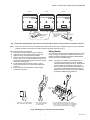
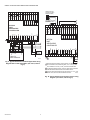
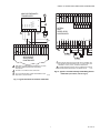
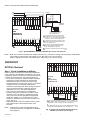
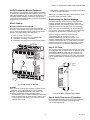
Excel 10
W7753A Unit Ventilator Controller
INSTALLATION INSTRUCTIONS
PRODUCT DESCRIPTION
The W7753A Controller communicates via the 78 kilobaud
Echelon® LonWorks® E-Bus Network.
The W7753A Unit Ventilator Controller is a Free Topology
Transceiver (FTT) LONMARK® Compliant Unit Vent controller
in the Excel 10 family product line.
Allowable input/output connections consist of wall module
points plus two additional resistive sensor inputs, two voltage/
current inputs, four digital inputs and eight digital Triac
outputs.
This controller can be used to monitor/control HVAC
equipment, lighting, and other miscellaneous loads in a
distributed network. The controller is field-mounted to the
equipment that it controls, and the controller wiring is attached
to the screw terminals located on the controller (see Fig. 1).
31
30 29
28 27 26
For the W7753A, any hardware driven by the Triac outputs
must have a minimum current draw, when energized, of
25 mA and a maximum current draw of 500 mA.
25 24 23
22
21 20 19
24
DI-4 GND
18 17
DI-3 DI-2 GN
16
2
D DI-1 24 VAC 1
3
4
VAC COM OU
5
6
T OUT OUT
7
8
OUT OUT OU
T OUT OUT
E LED BY
PASS SNSR GN
GND
D SET PT AI-1
1
2
3
4
5
OHM
6
7
GND A1-2
AI-3 GND AI4 22VDC
OHM V/mA
V/mA OUT
8
9
10
E-BUS
11 12 13
14
15
E-BUS
JACK
J3
M12688
Fig. 1. Excel 10 W7753A Unit Ventilator Controller.
Put Bar Code Here
95-7520—02
EXCEL 10 W7753A UNIT VENTILATOR CONTROLLER
INSTALLATION
The controller enclosure on the W7753A is constructed of a
sheet metal housing and a plastic factory snap-on cover. The
controller mounts using two screws inserted through the
plastic cover. Use the screws appropriate for the mounting
surface. The W7753A can be mounted in any orientation.
Ventilation openings were designed into the cover to allow
proper heat dissipation regardless of the mounting orientation.
Mount the W7753A in a position that allows clearance for
wiring, servicing and controller removal. Avoid mounting the
W7753A in areas where acid fumes or other deteriorating
vapors can attack the metal parts of the controller, or in areas
where escaping gas or other explosive vapors are present.
See Fig. 2 for mounting dimensions.
The W7753A can also be mounted using DIN rail (obtain
locally). If using DIN rail also purchase from Augat Inc. part
number 2TK2D DIN rail (adapter) two each (See Fig. 3).
2-1/8
(54)
31
30 29
28 27 26
25 24 23 22 21 20 19 18 17 16
24
3
2
4
6
5
7
8
24 VAC 1
DI-4 GND DI-3 DI-2 GND DI-1 VAC COM OUT OUT OUT OUT OUT OUT OUT OUT
E LED BYPASS SNSR GND SET PT AI-1 GND AI-2 AI-3 GND AI-4 22VDC E-BUS E-BUS
GND
OHM
OHM V/mA
V/mA OUT
JACK
1
2
3
4
5
6
7
8
9
10
11 12 13 14
15
J3
5-5/8
(143)
3-1/16
(77)
5-3/16 (132)
6 (152)
M12689
Fig. 2. W7753A mounting dimensions in in. (mm).
95-7520—02
2
EXCEL 10 W7753A UNIT VENTILATOR CONTROLLER
Power
The 24 Vac power from an energy-limited Class II Power
Source must be provided to each W7753A Controller. To
conform to Class II restrictions (U.S. only), transformers must
not be larger than 100 VA.
2
3
A transformer that meets CE mark requirements and that
meets the Low Voltage Directive (LVD) requirements must be
used in Europe for all installations of this product. More than
one W7753A Controller can be powered by a single
transformer. Fig. 4 shows power wiring details for a single
controller and Fig. 5 depicts multiple controllers using one
transformer.
IMPORTANT
Use the heaviest gauge wire available, up to 14
AWG (2.0 mm2) with a minimum of 18 AWG
(1.0 mm2), for all power and earth ground wiring.
Screw type terminal blocks are designed to accept
up to two 14 AWG (2.0 mm2) conductors, one on
each side of the terminal screw. More than two wires
that are 14 AWG (2.0 mm2) can be connected with a
wire nut. Include a pigtail with this wire group and
attach the pigtail to one side of the terminal block.
1
M6857
Fig. 3. W7753A DIN rail mounting.
OUTPUT
DEVICE
POWER
Wiring
All wiring must comply with applicable electrical codes and
ordinances or as specified on installation wiring diagrams.
Controller wiring on the W7753A is terminated to the screw
terminal blocks located on the top and the bottom of the
controller.
NOTES:
—
—
—
—
TRANSFORMER
TRIAC LINES
TO ACTUATORS
AND
CONTACTORS
W7753A
CONNECT POWER TO
TERMINALS 24 AND 25
For multiple controllers operating from a single
transformer, the same side of the transformer
secondary must be connected to the same power
input terminal in each controller. The ground
terminal (1 on the W7753A) must be connected to
a verified earth ground for each controller in the
group (see Fig. 5). (Controller configurations are
not necessarily limited to three controllers, but the
total power draw including accessories cannot
exceed 100 VA when powered by the same
transformer (U.S. only). See System Engineering
form 74-2964 for power wiring recommendations.)
All loads on an Excel 10 W7753A Controller must
be powered by the same transformer that powers
the Excel 10 W7753A Controller. A W7753A
Controller can use separate transformers for
controller power and load power.
Keep the earth ground connection (terminal 1)
wire run as short as possible. Refer to Fig. 9
through 14.
Do not connect the analog or digital ground
terminals (5, 8, 11, 27 and 30) to earth ground.
Refer to Fig. 9 through 14.
25 24
22 20
1
EARTH
GROUND
M12681
Fig. 4. Power wiring details; one Excel 10 per transformer.
NOTES:
—
—
Unswitched 24 Vac power wiring can be run in the
same conduit as the E-Bus cable.
Maintain at least three-inch (76 mm) separation
between Triac outputs and E-Bus wiring
throughout the installation.
See the following IMPORTANT on Heating and Cooling
Equipment (UL 1995, U.S. only).
IMPORTANT
If the W7753A Controller is used on Heating and
Cooling Equipment (UL 1995, U.S. only) and the
transformer primary power is more than 150 volts,
connect the transformer secondary to earth ground
(see Fig. 6). For these applications, only one
W7753A Excel 10 controller can be powered by each
transformer.
3
95-7520—02
EXCEL 10 W7753A UNIT VENTILATOR CONTROLLER
24 VAC
120/240 VAC
TRANSFORMER
W7753A
25 24
1
W7753A
W7753A
25 24
1
EARTH
GROUND
25 24
1
EARTH
GROUND
EARTH
GROUND
M12682
Fig. 5. Power wiring details for two or more Excel 10s per transformer.
24 VAC
LINE VOLTAGE
GREATER
THAN 150 VAC
TRANSFORMER
1
W7753A
EARTH
GROUND
1
EARTH
GROUND
1 IF THE W7750 CONTROLLER IS USED IN UL 1995 EQUIPMENT AND THE
PRIMARY POWER IS MORE THAN 150 VOLTS, GROUND ONE SIDE OF
M12680
TRANSFORMER SECONDARY.
Fig. 6. Transformer power wiring details for one Excel 10
used in UL 1995 equipment (U.S. only).
Communications
Refer to E-Bus Wiring Guidelines, form 74-2865, for a
complete description of E-Bus network topology rules.
Approved cable types for E-Bus communications wiring are
Level IV 22 AWG (0.34 mm2) plenum and non-plenum rated
unshielded, twisted pair, solid conductor wire. For nonplenum
areas, U.S. part AK3781 (one pair) or U.S. part AK3782 (two
pair) can be used. In plenum areas, U.S. part AK3791 (one
pair) or U.S. part AK3792 (two pair) can be used.
Communications wiring can be run in a conduit, if needed,
with non-switched 24 Vac or sensor wiring. If a longer E-Bus
network is required, a Q7740A 2-way or Q7740B 4-way
repeater can be added to extend the length of the E-Bus. Also
a Q7751A Router can be added to partition the system into
two segments and effectively double the length of the E-Bus.
Only one router is allowed with each Excel 10 Zone Manager,
and each network segment can have a maximum of one
repeater.
Pull the cable to each device on the E-Bus and connect to
communication terminals 14 and 15 (W7753A).
95-7520—02
4
NOTES: (For Communications Wiring)
—
All field wiring must conform to local codes and
ordinances (or as specified on the installation
drawings).
—
Approved cable types for E-Bus communications
wiring is Level IV 22 AWG (0.34 mm2) plenum
and non-plenum rated unshielded, twisted pair,
solid conductor wires. For nonplenum areas, U.S.
part AK3781 (one pair) or U.S. part AK3782 (two
pair) can be used. In plenum areas, U.S. part
AK3791 (one pair) or U.S. part AK3792 (two pair)
can be used.
—
Unswitched 24 Vac power wiring can be run in the
same conduit as the E-Bus cable.
—
Do not bundle output wires with sensor, digital
input or communications E-Bus wires.
—
Do not use different wire types or gauges on the
same E-Bus segment. The step change in line
impedance characteristics would cause unpredictable reflections on the E-Bus. When using different types is unavoidable, use a Q7751A Router
at the junction.
—
In noisy (high EMI) environments, avoid wire runs
parallel to noisy power cables, motor control centers, or lines containing lighting dimmer switches,
and keep at least 3 in. (76 mm) of separation
between noisy lines and the E-Bus cable.
—
Each daisy-chained E-Bus segment that is on one
side of a Q7751A,B Router (can contain up to 60
Excel 10s) and has a length greater than 1640 ft.
(500m) must have two E-Bus 209541B
Termination Modules, one at each end of the
daisy-chain wiring run.
—
Make sure that neither of the E-Bus wires is
grounded.
NOTE: If a 209541B Termination Module is required at a the
UV controller, connect two of the three termination
module wires to the E-Bus terminals. Selecting the
appropriate two wires depends on the E-Bus network
topology. Refer to the E-Bus Wiring Guidelines, form
74-2865, and the Excel 10 FTT Termination Module
Installation Instructions, form 95-7554. For example,
using a doubly terminated daisy-chained bus topology, if controllers are on either end of an E-Bus wire
run, mount the termination module on the appropriate terminals as shown in Fig. 7.
EXCEL 10 W7753A UNIT VENTILATOR CONTROLLER
W7753A
W7753A
1415
BROWN
W7753A
1415
1415
ORANGE
PART NO. 209541B
TERMINATION
MODULE
PART NO. 209541B
TERMINATION
MODULE
BROWN
ORANGE
M12690
Fig. 7. Termination modules (place a wire nut on each remaining wire that is not connected to a controller or device).
NOTE: When two or more wires are to be attached to the same terminal, other than 14 AWG (2.0 mm2), be sure to twist them
together. Deviation from this rule can result in improper electrical contact. See Fig. 8.
Wire to the terminal blocks as follows:
1. Strip 3/8 in. (10 mm) insulation from the conductor.
2. Insert the wire in the required terminal location and
tighten the screw to complete the termination.
3. If two or more wires are being inserted into one terminal
location, strip 1/2 in. (13 mm) of insulation from the conductors then twist the wires together a minimum of three
turns before inserting them.
4. Cut the twisted end of the wires to 3/16 in. (5 mm)
before inserting them into the terminal and tightening
the screw.
5. Pull on each wire in all terminals to check for good
mechanical connection.
Wiring Details
The W7753A Controller has the terminal arrangements shown
in Fig. 9 through 14. Connection for operator access to the
E-Bus is provided by plugging the Serial LonTalk® Adapter
(SLTA) connector into the E-Bus jack.
NOTE: If an Excel 10 Controller or Zone Manager is not
connected to a good earth ground, the controller
internal transient protection circuitry is compromised
and the function of protecting the controller from
noise and power line spikes cannot be fulfilled. This
can result in a damaged circuit board and require
replacement of the controller. Refer to job drawings
for specific installation wiring diagrams.
TWO 14 AWG
(2.0 MM2) WIRES
3/8
(10)
1.
STRIP 3/8 IN. (10 MM) FROM WIRES
TO BE ATTACHED AT ONE TERMINAL.
2. TWIST WIRES TOGETHER
WITH PLIERS (A MINIMUM
OF THREE TURNS).
3. CUT TWISTED END OF WIRES TO 3/16 IN. (5 MM)
BEFORE INSERTING INTO TERMINAL AND TIGHTENING
SCREW. THEN PULL ON EACH WIRE IN ALL TERMINALS
TO CHECK FOR GOOD MECHANICAL CONNECTION.
M10086
Fig. 8. Attaching two or more wires at terminal blocks.
5
95-7520—02
20
19
18
17
16
WINDOW CONTACT
(CONTACT CLOSED =
WINDOWCLOSED)
3
+
-
OCCUPANCY SENSOR
(CONTACT CLOSED =
OCCUPIED)
24 VAC
17
OUT 7
16
OUT 8
OUT 5
18
OUT 6
OUT 3
OUT 4
DI-1
19
OUT 2
GND
OUT 1
DI-2
24 VAC
DI-3
24 VAC COM
GND
20
4
5
6
M29164
Fig. 9. Typical W7753A unit ventilator application wiring
diagram with T7770F wall module. (For note 2, refer to
Fig. 8.)
1
AI-4 V/mA
3
22 VDC OUT
2
1
GND
OUTSIDE
AIR CO
SENSOR
E GND
BYPASS
FAN
LED
NET 1
NET 2
SET PT
SENSOR
GND
TR23-F5
WALL MODULE
21
TRIAC EQUIVALENT CIRCUIT
W7753A
UNIT
VENTILATOR
CONTROLLER
J3
E-BUS
1 2 3 4 5 6 7 8 9 10
22
AI-3 V/mA
15
23
AI-2 OHM
14
24
GND
13
25
AI-1 OHM
12
26
SETPT
11
27
GND
10
28
SNSR
9
29
BYPASS
8
30
LED
22 VDC OUT
7
E-BUS
31
E-BUS
JACK
AI-4 V/mA
6
GND
SETPT
5
AI-3 V/mA
GND
4
AI-2 OHM
SNSR
3
GND
BYPASS
2
1
AI-1 OHM
LED
E GND
W7753A
UNIT
VENTILATOR
CONTROLLER
DI-4
3
TRIAC EQUIVALENT CIRCUIT
7
8
9
10
11
12
13
E-BUS
14
15
E-BUS
JACK
DI-1
21
OUT 7
GND
22
OUT 8
DI-2
23
OUT 6
DI-3
24
OUT 5
DI-4
25
OUT 3
26
OUT 4
27
OUT 2
28
OUT 1
29
24 VAC COM
30
24 VAC
31
GND
EXCEL 10 W7753A UNIT VENTILATOR CONTROLLER
J3
2
E-BUS
1 EARTH GROUND WIRE LENGTH SHOULD BE HELD TO A MINIMUM.
USE THE HEAVIEST GAUGE WIRE AVAILABLE, UP TO 14 AWG (2.O MM2)
WITH A MINIMUM OF 18 AWG (1.O MM2), FOR EARTH GROUND WIRE.
2 TO ASSURE PROPER ELECTRICAL CONTACT, WIRES MUST BE TWISTED
TOGETHER BEFORE INSERTION INTO THE TERMINAL BLOCK.
3 CONTACTS MUST BE SUITABLE FOR DRY SWITCHING, 5V AT 10 mA. USE
SEALED TYPE, GOLD FLASHED OR PIMPLED CONTACTS.
M12692
Fig. 10. Typical window and occupancy sensor wiring
diagram. (For note 2, refer to Fig. 8.)
95-7520—02
6
DECREASE
18
17
OUT 7
16
OUT 8
19
OUT 6
20
OUT 5
21
OUT 3
OUT 1
22
OUT 4
23
OUT 2
24
24 VAC COM
DI-1
25
24 VAC
DI-2
GND
DI-3
26
OUT 3
OUT 4
OUT 5
OUT 6
OUT 7
OUT 8
OPTIONAL 24 VAC WIRING TO NEXT CONTROLLER.
3
USE 1/4 IN (6 MM) PNEUMATIC TUBING. MINIMUM BRANCH LINE
MUST BE 6 FT. (1.8M) OR LONGER.
6
C7600C
7
8
9
10
11
12
13
E-BUS
14
15
J3
2
+
E-BUS
S
HUMIDITY
(4 TO 20mA)
E-BUS
JACK
5
22 VDC OUT
OUT 2
2
4
AI-4 V/mA
OUT 1
MAKE SURE ALL TRANSFORMER/POWER WIRING IS AS SHOWN;
REVERSING TERMINATIONS RESULTS IN EQUIPMENT
MALFUNCTION.
3
1
W7753A UNIT
VENTILATOR
CONTROLLER
1
2
1
GND
16
AI-3 V/mA
17
AI-2 OHM
18
GND
19
SETPT
20
TRIAC EQUIVALENT CIRCUIT
AI-1 OHM
21
GND
22
SNSR
23
BYPASS
24
E GND
25
24 VAC
26
24 VAC COM
27
DI-1
DI-2
28
GROUND
DI-3
DI-4
GROUND
29
27
LED
INCREASE
24 (N)
24 (H)
24 (N)
24 (H)
+
-
30
28
W7753A
UNIT
VENTILATOR
CONTROLLER
24 VAC
31
29
3
B
PNEUMATIC
VALVE
2
30
M
M
1
31
DI-4
MMC325 PNEUMATIC
TRANSDUCER
GND
EXCEL 10 W7753A UNIT VENTILATOR CONTROLLER
C7600C
+
S
ENTHALPY
(4 TO 20mA)
1 EARTH GROUND WIRE LENGTH SHOULD BE HELD TO A MINIMUM. USE
THE HEAVIEST GAUGE WIRE AVAILABLE, UP TO 14 AWG (2.O MM2) WITH
A MINIMUM OF 18 AWG (1.O MM2), FOR EARTH GROUND WIRE.
2 TO ASSURE PROPER ELECTRICAL CONTACT, WIRESMUST BE TWISTED
TOGETHER BEFORE INSERTIONINTO THE TERMINAL BLOCK.
M12695
Fig. 12. Typical 4 to 20 mA Humidity and Enthalpy Sensor
to W7753A. (For note 2, refer to Fig. 8.)
M12693
Fig. 11. Typical Pneumatic Transducer to W7753A.
7
95-7520—02
EXCEL 10 W7753A UNIT VENTILATOR CONTROLLER
21
20
19
18
17
16
OUT 2
OUT 3
OUT 4
OUT 5
OUT 6
OUT 7
OUT 8
PWM OUTPUT
FROM CNTRL
22
PWM
(H 24 VAC)
23
24 (N)
24
24 (H)
25
OUT 1
26
24 VAC
27
24 VAC COM
28
DI-1
29
DI-2
DI-4
PWM VALVE ACTUATOR
GND
30
ML7984B
DI-3
31
GND
+
24 VAC
-
C
B
T6 T5
W
R
2
PWM VALVE
ACTUATOR
3
1 2 3 4
ON
22 VDC OUT
7
8
9
10
11
12
13
OFF
4
CONFIGURATION DIP SWITCHES
(LOCATED ADJACENT TO THE
INPUT TERMINAL BLOCK)
E-BUS
JACK
AI-4 V/mA
6
GND
SETPT
5
AI-3 V/mA
GND
4
AI-2 OHM
SNSR
3
GND
BYPASS
2
1
TRIAC EQUIVALENT CIRCUIT
AI-1 OHM
LED
E GND
W7753A
UNIT
VENTILATOR
CONTROLLER
E-BUS
14
15
J3
2
1
E-BUS
1 EARTH GROUND WIRE LENGTH SHOULD BE HELD
TO A MINIMUM. USE THE HEAVIEST GAUGE WIRE
AVAILABLE, UP TO 14 AWG (2.O MM2) WITH A MINIMUM
OF 18 AWG (1.O MM2), FOR EARTH GROUND WIRE.
2 TO ASSURE PROPER ELECTRICAL CONTACT, WIRES
MUST BE TWISTED TOGETHER BEFORE INSERTION
INTO THE TERMINAL BLOCK.
3 MAKE SURE ALL TRANSFORMER/POWER WIRING
IS AS SHOWN:REVERSING TERMINATIONS WILL
RESULT IN EQUIPMENT MALFUNCTION.
4 TURN POWER OFF BEFORE SETTING THE DIP SWITCHES.
M12694
Fig. 13. Typical PWM Valve Actuator to W7753A. (For note 2, refer to Fig. 8.)
NOTE: Make sure to set the Configuration DIP Switch as shown in Fig. 13. Switches 1 through 3 set the timing of the ML7984B
valve actuator to match the W7753A outputs (0.1 sec. Min. with a max. time of 25.6 sec.).
Switch 4 determines the action of the actuator (Off = Direct Acting, On = Reverse Acting).
NOTE: All wiring must comply with applicable electrical
codes and ordinances or as specified on installation
wiring diagrams.
95-7520—02
8
GND
OUT
+V
1
17
16
AI-2 OHM
AI-3 V/mA
GND
AI-4 V/mA
22 VDC OUT
TRIAC EQUIVALENT CIRCUIT
GND
6
18
OUT 7
DI-1
SETPT
5
C7600B
19
AI-1 OHM
GND
4
20
OUT 8
GND
SNSR
3
21
7
8
9
10
11
12
13
HUMIDITY
SENSOR
(2 TO 10 VOLT)
E-BUS
JACK
DI-2
BYPASS
2
1
22
OUT 6
DI-3
23
W7753A
UNIT
VENTILATOR
CONTROLLER
LED
Inspect all wiring connections at the W7753A terminals and
verify compliance with installation job drawings. If any wiring
changes are required, first be sure to remove power from the
controller before starting work. Pay particular attention to:
— 24 Vac power connections. Verify that multiple controllers
powered by the same transformer are wired with the
transformer secondary connected to the same input
terminal numbers on each W7753A. See Fig. 5. (Controller
configurations are not necessarily limited to three
controllers, but the total power draw including accessories
cannot exceed 100 VA when powered by the same
transformer (U.S. only). See System Engineering,
form 74-2964, for power wiring recommendations.
— Controller wiring. Be sure that each controller is wired
(terminal 1) on the W7753A to a verified earth ground
using a wire run as short as possible with the heaviest
gauge wire available, up to 14 AWG (2.0 mm2) with a
minimum of 18 AWG (1.0 mm2) for each controller in the
group. See Fig. 4.
— Verify Triac wiring to external controllers uses the proper
load power/24 Vac hot terminal (terminal 25 on the
W7753A).
E GND
Step 1. Check Installation and Wiring
24
OUT 5
GND
W7753A Checkout
25
OUT 3
26
OUT 4
27
OUT 2
28
OUT 1
29
24 VAC
30
24 VAC COM
31
DI-4
CHECKOUT
E-BUS
14
15
J3
2
E-BUS
1 EARTH GROUND WIRE LENGTH SHOULD BE HELD TO A MINIMUM. USE
THE HEAVIEST GAUGE WIRE AVAILABLE, UP TO 14 AWG (2.O MM2) WITH
A MINIMUM OF 18 AWG (1.O MM2), FOR EARTH GROUND WIRE.
2 TO ASSURE PROPER ELECTRICAL CONTACT, WIRESMUST BE TWISTED
TOGETHER BEFORE INSERTIONINTO THE TERMINAL BLOCK.
M12696
Fig. 14. Typical 2 to 10 Volt DC humidity sensor to
W7753A. (For note 2, refer to Fig. 8.)
EXCEL 10 W7753A UNIT VENTILATOR CONTROLLER
Verify Termination Module Placement
The installation wiring diagrams should indicate the locations
for placement of 209541B Termination Module(s). Refer to the
E-Bus Wiring Guidelines, form 74-2865, and the Excel 10 FTT
Termination Module Installation Instructions, form 95-7554.
Correct placement of the termination module(s) is required for
proper E-Bus communications.
Step 2. Startup
W7753A CONTROLLER STATUS LED
The LED on the front and center of a W7753A Controller
provides a visual indication of the status of the controller. See
Fig. 15. When the W7753A receives power, the LED should
appear in one of the following allowable states:
1.
2.
3.
4.
Off—no power to the processor.
Continuous On—processor is in initialized state.
Slow Blink—controlling, normal state.
Fast Blink—when the Excel 10 has an alarm condition.
W7753A
• Node Number: This is the Excel 10 node that has the alarm
condition (see Network Statics).
Alarm Type: The specific alarm being issued. An Excel 10 can
provide the alarm types listed in Table 1.
Broadcasting the Service Message
The Service Message allows a device on the E-Bus to be
positively identified. The Service Message contains the
controller ID number and, therefore, can be used to confirm
the physical location of a particular Excel 10 in a building.
There is one method of broadcasting the Service Message
from an Excel 10 W7753A Controller. This uses a hardware
push button on the side of the controller (see Fig. 16).
When an Assign ID command is issued from the
commissioning tool, the node goes into the
SERVICE_MESSAGE mode for five minutes. In the
SERVICE_MESSAGE mode, pressing the service pin on the
controller or the bypass button on a wall module causes the
Service Message to be broadcast on the network. All other
functions are normal in the SERVICE_MESSAGE mode.
Step 3. I/O Tests
31
30 29
28 27 26
The controller must be configured using the Excel 10 E-Vision
PC configuration tool. Once this is done, the W7753A can be
commanded to MANUAL mode, and each output can be
exercised/viewed to verify proper wiring connections and
equipment operation. See the Excel 10 E-Vision Users Guide,
form 74-2588 for details on configuring and testing W7753A
Controllers.
25 24 23
22
21 20 19
24
DI-4 GND
18 17
DI-3 DI-2 GN
16
2
D DI-1 24 VAC 1
3
4
VAC COM OU
5
6
T OUT OUT
7
8
OUT OUT OU
T OUT OUT
SERVICE
PIN
BUTTON
E LED BYP
ASS SNSR GND
GND
SET PT AI-1
1
2
3
4
5
OHM
6
7
GND A1-2
AI-3 GND AI-4
22VDC
OHM V/mA
V/mA OUT
8
9
10
E-BUS
11 12 13
14
15
E-BUS
JACK
J3
STATUS
LED
M12697
Fig. 15. LED location on W7753A.
ALARMS
When an Excel 10 has an alarm condition, it reports it to the
central node on the E-Bus (typically, the Excel 10 Zone
Manager, or Small Building Controller). See Table 1. The
information contained in an alarm message follows:
• Subnet Number: This is the E-Bus subnet that contains the
Excel 10 node that has the alarm condition. Subnet 1 is on
the Zone Manager side of the router; Subnet 2 is on the
other side of the router.
9
M10094
Fig. 16. Location of the service pin button.
Step 4. Verify Sequences of Operation
For the detailed descriptions of the sequences of operation,
see the Excel 10 Unit Ventilator System Engineering,
form 74-2964 Appendix B.
95-7520—02
EXCEL 10 W7753A UNIT VENTILATOR CONTROLLER
Table 1. Excel 10 Alarms.
Name of alarm or error bit
Alarm type
number
NO_ALARM
0
No alarms presently detected.
INPUT_NV_FAILURE
1
One or more NV inputs have failed while receiving an update within their
specified FAILURE_DETECT_TIME.
NODE_DISABLED
2
The control algorithm stopped because the controller is in DISABLED_MODE,
or FACTORY_TEST mode. The control is shut down and disabled until power is
cycled or the node is reset. See NOTE 1 below.
SENSOR_FAILURE
3
One or more sensors have failed.
FROST_PROTECTION_ALARM 4
The space temperature is below the frost alarm limit 42.8°F (6°C) when the
mode is FREEZE_PROTECT. The alarm condition remains until the
temperature exceeds the alarm limit plus hysteresis.
INVALID_SET_POINT
5
One of the Setpoints is not in the valid range.
LOSS_OF_AIR_FLOW
6
The Fan Status DI indicates that there is no air flow when the node is
commanding the fan to run. The control is shut down and disabled until power is
cycled or the node is reset. The alarm is not issued until FanFailTime seconds
have elapsed since the loss-of-flow condition was first reported.
DIRTY_FILTER
7
The pressure drop across the filter exceeds the limit and the filter requires
maintenance. The control runs normally.
SMOKE_ALARM
8
The smoke detector has detected smoke and the node has entered an
emergency state.
IAQ_OVERRIDE
9
The indoor air quality sensor has detected that the indoor air quality is poorer
than the desired standard and additional outdoor air is being brought into the
conditioned space.
LOW_LIM_ECON_CLOSE
10
The economizer has to close beyond the minimum position to prevent the
discharge air temperature from going below the discharge temperature low
limit.
DRIP_PAN_FULL
11
Drip pan maintenance is required. Cooling control is disabled. Fan continues to
run.
FREEZE_STAT
12
Very Cold Temperature detected inside the Unit Ventilator Cabinet. Control
closes OA Damper, and open heat valve.
OAQ_ALARM
13
The configured outdoor air quality sensor has detected CO or CO2 levels that
exceeds OaQStPt (plus 30 ppm hysteresis). When there is an OAQ_ALARM,
the economizer damper is closed.
RETURN_TO_NORMAL
128
Return to no alarm after being in an alarm condition. This code is added
numerically to another alarm code to indicate that the alarm condition has
returned to normal.
ALARM_NOTIFY_DISABLED
255
The alarm reporting was turned off by the nviManualMode. No more alarms are
reported until nviManualMode turns on alarm reporting or upon application
restart.
NOTE: The node can be reset by switching the node to MANUAL and then switching to the normal operating mode
(using DestManMode).
Also, the Excel 10 network variables, AlarmLogX, where X is 1 through 5, that store the last five alarms to occur in the
controller, are available. These points can be viewed through XBS, XI584 or E-Vision.
95-7520—02
10
EXCEL 10 W7753A UNIT VENTILATOR CONTROLLER
11
95-7520—02
EXCEL 10 W7753A UNIT VENTILATOR CONTROLLER
Automation and Control Solutions
Honeywell International Inc.
Honeywell Limited-Honeywell Limitée
1985 Douglas Drive North
35 Dynamic Drive
Golden Valley, MN 55422
Toronto, Ontario M1V 4Z9
Honeywell GmbH
Böblinger Straße 17
D-71101 Schönaich
customer.honeywell.com
® U.S. Registered Trademark
© 2009 Honeywell International Inc.
95-7520—02 K.K. Rev. 03-09