1
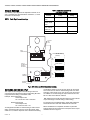
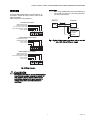
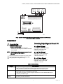
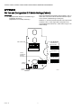
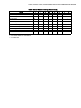
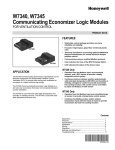
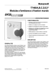
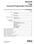
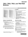
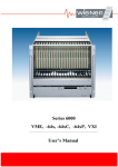
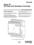
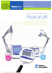
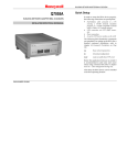
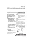
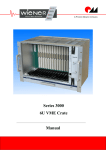
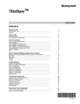
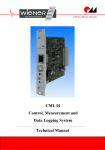
H7625A, H7635A, H7626A, H7636A Series
2000 Humidity/Temperature Sensors
WALL-MOUNT MODELS
INSTALLATION INSTRUCTIONS
APPLICATION
The H7625A, H7626A, H7635A and H7636A Wall-Mount
Humidity/Temperature Sensors are universal Relative
Humidity transmitters that can be powered with either a +18 to
40 Vdc or 24 Vac supply. The devices are half wave rectified.
The transmitter also includes either a 20K ohm NTC
thermistor or a 1K platinum PTC (compatible with the T775)
for optional temperature use.
The humidity sensors are designed with a field selectable 4 to
20 mA, 0 to 5 Vdc, or 0 to 10 Vdc output signal equivalent to 0
to 100% RH. All units are shipped from the factory with a
default setting to accept AC power with three-wire, 0 to 10 Vdc
output.
INSTALLATION
When Installing this Product...
1.
2.
3.
4.
Read these instructions carefully. Failure to follow them
could damage the product or cause a
hazardous condition.
Check ratings given in instructions and on the product to
ensure the product is suitable for your application.
Installer must be a trained, experienced service
technician.
After installation is complete, check out product
operation as provided in these instructions.
CAUTION
Equipment Damage Hazard.
Improper wiring can damage the sensor beyond
repair.
Follow the wiring instructions carefully.
Location
Install the device where it cannot be affected by:
— drafts, or dead spots behind doors and in corners.
— hot or cold air from ducts.
— radiant heat from sun or appliances.
— concealed pipes and chimneys.
— unheated (uncooled) areas such as an outside wall behind
the device.
Mounting
The housing base mounts over standard 2 in. x 4 in. single
gang junction box or flush to the wall:
1. Install the sensor about 5 ft (1.5m) above the floor in an
area with good air circulation at average humidity and
temperature. (See Fig. 1.)
2. Ensure the device receives adequate airflow.
3. Wire the device. (See Fig. 5 through 4.)
4. Ensure proper DIP switch settings.
5. Apply power to the unit.
6. Snap the cover into position.
7. Turn out the 1/16 in. allen screws at the bottom of the
enclosure until the cover cannot be removed.
CAUTION
Electrical Shock or Equipment Damage Hazard.
YES
Can shock individuals or short equipment
circuitry.
Disconnect power supply before installation.
NO
NO
NO
5 FEET
(1.5 METERS)
M4823A
Fig. 1. Typical sensor location.
Put Bar Code Here
62-0327-03
H7625A, H7635A, H7626A, H7636A SERIES 2000 HUMIDITY/TEMPERATURE SENSORS
Output Settings
Table 1. Controller Compatibility
and Output Settings.
The humidity output signal can be adjusted for 0-5Vdc, 0-10
Vdc or 4-20 mA using the switch block. Switches 6, 7, and 8
are used to set the output.
Required Sensor Output
Setting
Controller
NOTE: Refer Fig. 2 for switch settings.
LONSPEC™
Setting
W7750, W7760,
W7761
4-20 mA
C7600C
W7750B,C
W7760C, W7753,
W7760
0-10 Vdc (default)
H7621/31
T7350, XL50,
XL100, XL500 XF
Modules, XFL
0-10 Vdc (default)
n/a
Non-Honeywell
0-5 Vdc
n/a
FACTORY
USE
ONLY
WIRE
CONNECTIONS
TB1
0-10 VDC OUTPUT
(DEFAULT)
4-20mA VIN COM VOUT +TEMP-
SW1
ON
ON
OFF
1
2
3
4
5
6
7
8
0-5VDC OUTPUT
OUTPUT,
CALIBRATION
AND TEST
SWITCHES
SW1
ON
ON
OFF
1
2
3
4
5
6
7
8
4-20mA OUTPUT
SW1
ON
SW1
ON
HUMIDITY
SENSOR
1
2
S1
P2
3
4
5
6
7
8
ON
OFF
1
2
3
4
5
6
7
8
P1
S2
S3
SPAN ZERO
TEMPERATURE
SENSOR
M33151
Fig. 2. DIP switch and Wire Connection locations.
REVERSE ACTING OUTPUT
mode. When switch 2 is set to ON, the output can be used to
show if the unit is in direct or reverse acting mode. For direct
acting the output will be 1V for 0-5V, 2V for 0-10V, and 7.2mA
for 4-20mA. For reverse acting the output will be 4V for 0-5V,
8V for 0-10V, and 16.8mA for 4-20mA.
The output can be changed to reverse acting mode. The
output range stays the same but the corresponding RH value
is opposite. Direct Acting is the default mode.
Example: Direct Acting (DA)
0-10V output mode
0V = 0% RH and 10V = 100% RH
With switches 2 and 4 ON, each time switch 5 is set to ON the
output will change to reverse acting or direct acting.
Reverse Acting (RA)
0-10V output mode,
0V = 100% and 10V = 0%
To reset the unit to the default setting, toggle both switches 5
and 6 ON then OFF while both switches 2 and 4 are ON.
When all calibration is completed, remember to place the
switches back into the positions that correspond to the output
needed as shown in Figure 3.
To change the transmitter to reverse acting or back to direct
acting, set switch 4 ON to put the unit in setup mode. After
switch 4 is on, switch 2 will put the unit in direct/reverse acting
62-0327—03
2
H7625A, H7635A, H7626A, H7636A SERIES 2000 HUMIDITY/TEMPERATURE SENSORS
WIRING
IMPORTANT
When using shielded cable, ground the shield only at
the controller end (see Fig. 4). Grounding both ends
can cause a ground loop.
A 16 to 22 AWG shielded cable is recommended for all
transmitters. Twisted pair may be used for 2-wire current
output transmitters.
Refer to Figure 3 for wiring diagrams.
mA OUTPUT
TRANSDUCER
ONLY
VOLTAGE OUTPUT SIGNAL
TEMPERATURE SENSORTEMPERATURE SENSOR+
0-10 OR 0-5 VDC OUTPUT SIGNAL
SUPPLY GROUND/SIGNAL COMMON
SUPPLY VOLTAGE
18 TO 36 Vdc
POWER SUPPLY
Vin
+
4-20mA
–
CONTROLLER, METER
OR RECORDER
+ INPUT SIGNAL
– COMMON
TB1
GROUND
4-20mA VIN COM VOUT +TEMP-
2 WIRE CURRENT OUTPUT SIGNAL
M22528A
TEMPERATURE SENSORTEMPERATURE SENSOR+
Fig. 4. Typical wiring diagram for transducer with two-wire mA
output with external DC power supply.
SUPPLY VOLTAGE
4-20mA OUTPUT
TB1
4-20mA VIN COM VOUT +TEMP-
3 WIRE CURRENT OUTPUT SIGNAL
TEMPERATURE SENSORTEMPERATURE SENSOR+
SUPPLY GROUND/SIGNAL COMMON
SUPPLY VOLTAGE
4-20mA OUTPUT
TB1
4-20mA VIN COM VOUT +TEMPM31180A
Fig. 3. Wiring Diagrams
CAUTION
It is recommended that you use an isolated UL-listed
class 2 transformer when powering the unit with 24
VAC. Failure to wire the devices with the correct
polarity when sharing transformers may result in
damage to any device powered by the shared
transformer.
3
62-0327—03
H7625A, H7635A, H7626A, H7636A SERIES 2000 HUMIDITY/TEMPERATURE SENSORS
TR23 Remote Sensor
12 11 10 9
8
7
6
5
4 3
2
OUTDOOR
AIR
SENSOR
1
HEAT
RELAY 2
DISCHARGE
AIR
SENSOR
T7350
SUBBASE
T5
T6
T7
T4
HS
HC
T3
OS
OS
AS
AS
HP
M
M
X
RH
COMPRESSOR
CONTACTOR 4
W3/Y4 Y3
COMPRESSOR
CONTACTOR 2
W2
Y2
Y1
G
5
RC
AUX
W1
COMPRESSOR
CONTACTOR 3
3
MOTION
SENSOR
VOUT COM VIN
(0-10 Vdc)
(Vac)
COMPRESSOR
CONTACTOR 1
HUMIDITY SENSOR
4
1
ECONOMIZER
L2
2
FAN
RELAY
HEAT
RELAY 1
L1
(HOT)
1
POWER SUPPLY. PROVIDE DISCONNECT MEANS AND OVERLOAD PROTECTION AS REQUIRED.
2
ENSURE TRANSFORMER IS SIZED TO HANDLE THE LOAD.
3
HEAT/COOL SYSTEMS WITH ONE TRANSFORMER REQUIRE THE FACTORY-INSTALLED JUMPER.
4
USE ECONOMIZER INSTRUCTIONS FOR INSTALLATION DIRECTIONS.
5
HC AND HP PROVIDE 24 VAC TO THE HUMIDITY SENSOR.
M31307
Fig. 5. Humidity Sensor (0-10 Vdc output) wiring with T7350
(use with RH/Temperature combination T7350 units only).
PWR
+
–
COM
O OUT
COM
O OUT
19
20
21
22
23
2
O VOUT (0-10 Vdc)
1
2
3
4
5
6
7
8
9
10
11
12
13
E
GND
AI
1
AI
2
AI
GND
AI
3
AI
4
AI
GND
AI
5
AI
6
AI
GND
AI
7
AI
8
AI
GND
DI
1
DI
2
DI
3
DI
4
25
26
27
28
OUT OUT OUT OUT OUT OUT OUT OUT
1
2
3
4
5
6
7
8
18
+ VIN (Vac) +
– COM
–
PWR
W7760A
17
H76XX
P7640
P7640
+
–
24
1
GND GND
29
15
16
ANALOG
OUT
AO
AO
1
2
14
AO
GND
24
24
24
24
24
24
24 OUT 21 GND
VAC VAC VAC VAC VAC VAC VAC COM VDC
COM COM
OUT
31
32
33
34
35
36
37
38
39
40
E-BUS
41
42
E-BUS
43
L1
(HOT)
L2
1
POWER SUPPLY. PROVIDE DISCONNECT MEANS AND OVERLOAD PROTECTION AS REQUIRED.
2
TEMPERATURE SIGNAL CONNECTIONS ARE NOT POLARITY SENSITIVE.
M18302C
Fig. 6. Typical wiring diagram for 5-wire temperature/humidity sensor with Vdc output
(used with the XL15A controller).
62-0327—03
4
44
H7625A, H7635A, H7626A, H7636A SERIES 2000 HUMIDITY/TEMPERATURE SENSORS
HUMIDITY SENSOR
4-20mA VIN
COM VOUT
+TEMP
DO-1
DO-2
COM
DO-3
DO-4
COM
DO-5
DO-6
COM
DO-7
DO-8
COM
24 VAC
24 VAC COM
EGND
SHLD
SBUS1
SBUS2
NET-1
NET-2
AO-1
COM
AO-2
AO-3
COM
D1-1
D1-2
COM
D1-3
D1-4
20VDC
U1-1
COM
U1-2
U1-3
COM
U1-4
U1-5
COM
U1-6
2 2 2 2 2 2 2 2 2 3 3 3 3 3 3 3 3 3 3 4
1 2 3 4 5 6 7 8 9 0 1 2 3 4 5 6 7 8 9 0
1 1 1 1 1 1 1 1 1 1 2
9 0 1 2 3 4 5 6 7 8 9 0
1 2 3 4 5 6 7 8
24 VAC
+
24 VAC
COM
M31268
Fig. 7. Typical wiring diagram for 5-wire temperature/humidity sensor with Vdc output
(used with the Spyder controller).
CHECKOUT
Converting Output Signal to Percent RH
CAUTION
Equipment Damage Hazard.
4 to 20mA Signal
Can short electric circuitry.
• Never connect 120 Vac to the transducer.
• Connect only DC voltage to a transducer intended
for DC supply.
((mA signal) -4) / 0.16 = percent RH
Example: 12mA output signal
(12-4) / 0.16 = 50% RH
0 to 5 Vdc Signal
NOTE: Use laboratory quality meters and gauges for applications requiring a high degree of
accuracy.
1.
2.
3.
(VDC signal) / 0.05 = percent RH
Example: 1.25vdc output signal
1.25 / 0.05 = 25% RH
Verify that the transducer is mounted in the correct position.
Verify appropriate input signal and voltage supply.
Verify appropriate configuration range.
0 to 10 Vdc Signal
(VDC signal) / 0.10 = percent RH
Example: 7.50vdc output signal
7.50 / 0.10 = 75% RH
Table 2. Troubleshooting.
Problem
Items to Check
No reading
• Verify correct supply voltage at the power terminal blocks.
• Verify correct wiring configuration and DIP switch settings per Figures 2 and 3.
• Verify that terminal screws are connected tightly with all wires firmly in place.
Erratic readings
• Verify all wires are terminated properly.
• Ensure that there is no condensation on the board.
• Verify clean input power. In areas of high RF interference or noise, shielded cable can be
necessary to stabilize signal.
Inaccurate
readings
• If you suspect that the transmitter is not reading within the specified tolerance, please contact
the factory for further assistance
5
62-0327—03
H7625A, H7635A, H7626A, H7636A SERIES 2000 HUMIDITY/TEMPERATURE SENSORS
APPENDIX
RH Test and Configuration DIP Switch Settings (Table 3)
IMPORTANT
• Only adjust these switches for troubleshooting or
recalibrating the sensor.
(Adjustment is not normally necessary.)
Test mode will make the transmitter output a fixed 0%, 50%, or
100% value. The sensor will not affect the transmitter output.
This is used for troubleshooting or testing only.
Switches 1, 2, and 3 are used for test mode. The output will be
a fixed 0%, 50%, or 100% signal that corresponds to the
output selected with switches 6, 7, and 8. Refer to Figure 4 for
switch settings.
TEST SELECTION
SWITCHES (SW1)
WIRE CONNECTIONS
TB1
0% RH OUTPUT
SW1
ON
4-20mA VIN COM VOUT +TEMP-
ON
OFF
1
2
3
4
5
6
7
8
50% RH OUTPUT
SW1
ON
OUTPUT,
CALIBRATION
AND TEST
SWITCHES
ON
OFF
1
2
3
4
5
6
7
8
100% RH OUTPUT
SW1
ON
SW1
ON
OFF
ON
HUMIDITY
SENSOR
1
2
3
4
5
6
7
1
2
3
4
5
6
7
8
8
S1
P2
P1
S2
S3
SPAN ZERO
TEMPERATURE
SENSOR
62-0327—03
M33163
6
H7625A, H7635A, H7626A, H7636A SERIES 2000 HUMIDITY/TEMPERATURE SENSORS
Table 3. Test and Calibration Settings (8-Switch Block).
Setting
4-20mA Output
1
—
2
3
—
—
4
—
5
—
6
—
7
—
8
—
0-5 VDC Output
—
—
—
—
—
On
On
—
0-10 VDC Output
—
—
—
—
—
—
On
On
0% RH Output
On
—
—
—
—
—
—
—
50% RH Output
—
On
—
—
—
—
—
—
100% RH Output
—
—
On
—
—
—
—
—
Increment RH Output
—
—
—
On**
On
—
—
—
Decrement RH Output
—
—
—
On**
—
On
—
—
Reset to Original Calibration
—
—
—
On**
On
On
—
—
Reverse or Direct Acting
—
On
—
On**
On
—
—
—
Reverse or Direct Acting Reset
—
On
—
On**
On
On
—
—
* = Switch setting does not affect output
** = This switch needs to be activated first
— = Indicates OFF
7
62-0327—03
H7625A, H7635A, H7626A, H7636A SERIES 2000 HUMIDITY/TEMPERATURE SENSORS
CALIBRATION
NOTE: This is only a single point calibration. All transmitters
are factory calibrated to meet/exceed published
specifications. Field adjustment should not be necessary.
The dipswitch allows the user to calibrate the sensor through
the software. Setting switch 4 ON will put the transmitter into
setup mode allowing the increment and decrement to work.
Once in setup mode, the output will change to 50% (2.5V for
0-5V, 5V for 0-10V, 12mA for 4-20mA). Each increment or
decrement step will cause the output to change by 0.1V for 05V, 0.2V for 0-10V, and 0.32mA for 4-20mA in setup mode.
This can be used to show the user how far offset the
transmitter is. To see the starting point again set switch 1 ON.
This will show the 50% output again. When the unit is out of
setup mode the output will go back to RH output.
Decrement RH Output
This will shift the RH output linearly down in 0.5% steps.
Switch 4 must be set to ON first. After switch 4 is on, each
time switch 6 is set ON the RH output will decrease by 0.5%.
The decrease goes into effect each time switch 6 is set to ON.
Reset RH Output
This will reset the RH output back to the original calibration.
Switch 4 must be set to ON first. After switch 4 is on, toggle
switches 5 and 6 ON then OFF. After 5 and 6 are OFF slide
switch 4 OFF.
When all calibration is completed, remember to place the
switches back into the positions that correspond to the output
needed as shown in Figure 3.
Increment RH Output
This will shift the RH output linearly up in 0.5% steps. Switch 4
must be set to ON first. After switch 4 is on, each time switch 5
is set ON the RH output will increase by 0.5%. The increase
goes into effect each time switch 5 is set to ON.
Automation and Control Solutions
Honeywell International Inc.
1985 Douglas Drive North
Golden Valley, MN 55422
customer.honeywell.com
® U.S. Registered Trademark
© 2011 Honeywell International Inc.
62-0327—03 S.B. Rev. 11-11
Printed in United States