1
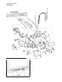
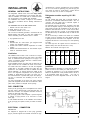
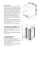
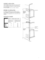
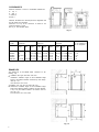
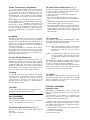
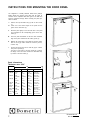
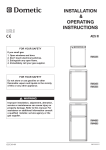
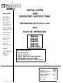
SERVI
United States
SALES OFFICES
DOMETIC SALES CORP.
INSTALLATION
AND
OPERATING INSTRUCTIONS
2320 Industrial Pkwy.
Elkhart, IN 46515
Phone 219-295-5226
DOMETIC SALES CORP.
14441 Bonelli St.
City of Industry, CA 91746
Phone 616-966-9431
DOMETIC SALES CORP.
1625-A Rock Mountain Blvd.
Stone Mountain, GA 30083
Phone 404-493-6214
DOMETIC SALES CORP.
7695 S.W. Hunziker Rd.
Portland, OR 97223
Phone 503-620-9510
DOMETIC SALES CORP.
2920 Avenue “E” East
Arlington, TX 76011
Phone 617-277-7211
DOMETIC SALES CORP.
East Oak Ridge Dr.
Rt. 9, Box 17 A
Hagerstown. MD 21740
Phone 301-797-0826
REFRIGERATOR FOR LP-GAS
AND
ELECTRIC OPERATION.
REFRIGERATOR
RM360
RM460
RM660
RM760
RM1300
Canada
Euroclean Canada Inc.
Dometic Recreation Division
666 Langs Drive
Cambridge, Ontario
N3H 2N7 Canada
(519) 653-8880
FOR YOUR SAFETY
If you smell gas:
1. Open windows.
2. Don’t touch electrical switches.
3. Extinguish any open flame.
4. Immediately call your gas supplier.
Page
Installation
Instructions for use
Gas equipment
Electric equipment
Maintenance
Fault tracing
Door panel
DSC # 303
9-10
10
10-11
11
11
12
REFRIGERATORS WlTH
PIEZ0 IGNITER
Fig. la
E
DCB
Fig. 4a
2
A
REFRIGERATORS WlTH
AUTOMATIC IGNITION
E
CB
A
Fig. 4b.
3
Fig. 5
Fig. 2
Clear blue colour of flame
Fig. 3
-
Gas equipment parts
1. Burner tube
2. Burner housing
3. Burner jet
4. Feeler point (thermocouple)
5. Flame failure safety device
6. Bypass screw
7. Gas/Electric thermostat
6. Pressure test gage connection
9. Capillary tube for thermostat
10. Shut-off valve
11. Piezo igniter (lighter)
12. Firing tip
24. Hexagon nut
Electric equipment parts
13. Flexible cord
14. Change-over switch
15.5Terminal block, 12 V DC
16. Reigniter
17. Relay
22. Cover
23. Terminal block, 12 V DC, on certain models only
4
Fig. 6
INSTALLATION
GENERAL INSTRUCTIONS
The refrigerators outlined hereon have been design certified
under ANS i! 21.19 Refrigerators by the American Gas Association for installation in a mobile home or recreational vehicle
and are approved by the Canadian Gas Association.
The certifications are, however, contingent on the installation
being made in accordance with the following instructions as
applicable.
The installation must in the USA conform with:
1. National Fuel Gas Code 2223.1-l 974
2. Mobile Homes Al 19.1-l 975
3. Recreational Vehicles Al 19 2-l 975
The unit must be electrically grounded in accordance with the
National Electric Code ANSI, Cl- 1978 when installed if an
external alternating current electrical source is utilized.
4. Any applicable local code
In Canada
1. Standard CGA 10.1 /CSA 2240.4, gas equipped mobile
housing and recreational vehicles
2. Sandard CSA 2240.61 electrical requirements for mobile
housing
3. Standard CSA Z240.6.2/C22.2 No 148 electrical requirements for recreational vehicles.
ged directly into a properly grounded three prong receptacle.
Do not cut or remove the grounding prong from this p!ug The
cord should be routed to avoid coming In contact with the
burner cover. flue cover or other hot components
Refrigerator models requiring 12 V DC
supply
On units provided with interior light or automatic reigniter or
both there is one additional terminal block marked " 12 V”. On
“Tri-Power” units with interior light or automatic reigniter or
both there are two additional blocks.
The refrigerator must be connected to the battery circuit with
two wires of adequate capacity to avoid voltage drop. The wire
gage should be chosen with consideration to the wire length in
accordance with table below. The 12 V circuit must be fused.
Maximum circuit fuse size: 15 Amps. for the models RM 360
and RM 460.20 Amps. for RM 660.30 Amps. for RM 760 and
RM 1300.
Do not use the body or chassis of the vehicle as a substitute
for either of the two conductors. No other electrical equipment
or lighting should be connected to the refrigerator circuit The
refrigerator will draw from 10 to 23 Amps at 12 Volt depending
on model.
The interior light and the reigniter must be connected to a
separate battery circuit and will draw about 1 Amp.
Maximum two conductor wire length in feet
AWG
RM360
125W
14
12
10
8
6
4
10
17
27
43
69
110
Ventilation
The installation shall be made in such a manner as to separate the combustion system from the living space of the mobile
home or recreational vehicle. Openings for air supply or for
venting of combustion products shall have a minimum dimension of not less than 1/4 inch.
Proper installation requires one lower fresh air intake and one
upper exhaust vent. The ventilation kits shown in this instruction booklet have been certified for use with the refrigerator
models listen in the tables. Certified vent system kits, see
separate list. The ventilation kits must be installed and used
without midification. An opening towards the outside at floor
level in the refrigerator compartment must be provided for
ventilation of heavier-than-air fuel gases. The lower vent of
the recommended kits is provided with proper size openings.
The flow of combustion and ventilating air must not be
obstructed.
For ready serviceability of the burner and control manifold
parts of the refrigerator the lower side vent is fitted with a iiftout
planel which provides an adequate access opening.
RM460
135w
9
15
25
40
64
102
RM660
175w
RM760
250W
7
12
19
31
49
79
5
8
13
22
34
55
CAUTION
Do not operate
4
7
12
19
31
50
Interior
light only
10W
17
35
55
85
135
220
the refrigerator on 12 Volt when the vehicle IS
parked. You will run out of battery in a rather short time.
If possible the installation of a 12 Volt operated refngerator
should be completed with a relay mounted either in the car or
in the recreational vehicle (see Fig below
) T h i s relay will
automatically cut out the refrigerator when the car motor is
stopped
GAS CONNECTION
Hook-up to the gas supply line is accomplished at the manual
gas valve, which is furnished with a 3/8” SAE (UNF 5/8”- 18)
male flare connection. All completed connections should be
checked for leaks with soapy water.
The gas supply system must incorporate a pressure regulator
to maintain a supply pressure of not more than 11 inches
water gage.
In case detailed instructions on the installation and connection
to the gas supply are required, contact your dealer or distributor.
ELECTRICAL CONNECTION
120 Volts A C
The refrigerator is equipped with a three prong (grounded)
plug for protection against shock hazards and should be plug-
RM1300
275W
Fig. 7
SPECIAL HINTS
The refrigerator must be installed in a substantial enclosure
and must be level. A spirit level is supplied with each refrigerator and by placing it in the freezer compartment one can level
the refrigerator both ways front to back and side to side. When
installing the refrigerator in the enclosure care should be taken
to ensure a complete sealing between the front frame of the
refrigerator and the top, sides and bottom of the enclosure.
For this purpose a length of sealing strip is applied to the rear
surfaces of the front frame. A sealing strip should also be
applied to the foremost floor of the enclosure as shown in fig 8.
The sealing should provide a complete isolation of the appliance combustion system from the vehicle interior.
Be careful not to damage the sealing strip applied to the floor
of the enclosure when the refrigerator is put in place.
In the front frame and in the base at the rear of the refrigerator
there are holes for screws for fixing the refrigerator in the
enclosure. (Fig. 13).
Any space between counter or storage area and the top of the
refrigerator must be blocked. The heat produced at the rear of
the refrigerator will otherwise become trapped in this space
making the top of the refrigerator hot and reducing the efficiency of the refrigerator.
Do not install so that an adjacent heat producing appliance will
affect the construction or performance of the refrigerator.
Fig. 8
TO CHANGE THE DOOR OPENING FROM
LEFT TO RIGHT OR VICE VERSA
Open the door and unscrew the two screws holding the top
front cover. The screws are accessible form beneath. Remove
the top hinge pin and lift out the door.
The lower pin for the refrigerator door should be shifted to the
opposite side.
The door can then be remounted. Before the top front cover is
refitted check that the door closes easily and that the gasket
seals well on all sides.
TO REMOVE AND REPLACE
THE REFRIGERATOR
Before working on the refrigerator make sure that 120 V A.C.
and optional 12 V D.C. leads are disconnected.
Unscrew the hexagon nut 24 and move the valve on the gas
line out of the bracket. Check that the valve slips out of the clip
connection with the switch shaft.
Loosen the screws fixing the refrigerator to the enclosure and
remove the refrigerator.
When replacing the refrigerator make sure that the sealing
strips are properly positioned. After reassembly the gas connection should be checked for leaks.
Fig. 13
CERTIFIED INSTALLATION
Certified installations require one roof vent and one lower side
vent or as optional one upper vent and one lower side vent.
The two alternatives are provided for by using the different kits
listed in the Appendix.
For further information contact your dealer or distributor.
METHODS OF INSTALLATION
Condenser
The methods of installation are shown in figures 9 and 10.
It is essential that all maximum or minimum dimensions are
strictly maintained as the performance of the refrigerator is
dependent on an adequate flow of air over the rear of the
refrigerator.
VENTILATION HEIGHTS
Refrigerator
41
Minimum ventilation heights in inches
Fig. 9
RM360
RM460
RM660
RM760
RM1300
Duct cross
section
area 5"x18"
Condenser
Fig. 10
7
CLEARANCES
Minimum clearances in inches to combustible materials are
G: Top 0
K: Side 0
L: Bottom 0
M: Rear 1
Clearance M between the rearmost part of the refngerator and
the wall behind the refrigerator
Clearance N on top of the condenser is related to the
minimum’ventilation height
See Fig 11 and examples below
Fig. 11
Refrigerator Overall
model
dimensions
Height
A
RM360
RM460
RM660
RM760
RM1300
Width
B
Installation
dimensions
Depth
C
Height
h
30 3/8
21 11/166 22 1/16
29 9/16
32 15/16623
24 11/16632 1/8
40 13/16623
24 11/166 40
52
23
24 11/166 51 3/16
57 15/166 24 15/166 24 11/16 57 1/8
Width
Recess
dimensions
Distance between
top of condenser to
top of refrigerator
W
Depth
d
Height
H
Width
W
20 1/4
21 9/16
21 9/16
21 9/16
23 7/16
20 3/16
22 3/4
22 3/4
22 3/4
22 3/4
29 3/4
32 5/16
40 3/16
51 3/8
57 1/2
20 1/22
21 13/16
21 13/16
21 13/16
23 13/16
Depth
D
21 3/16
23 3/4
23 3/4
23 3/4
23 3/4
EXAMPLES
The clearance N for the RM360 model
following way
IS
derived at in the
Installation with upper and lower side vents
N=Minimum ventilation height 37 minus installation height
29 9/1 6 plus distance between condenser top and refrigerator top 1 1/4
N=37-29 9/16+1 1/4=8 11/16
Installation with roof vent and lower side
N=Minimum ventilation height 31 minus
29 9/1 6 plus distance between condenser
or top 1 1/4 plus distance between roof
vent cap 5 1/4
N=31-29 9/16+1 1/4+5 1/4=7 15/16
vent
installation height
top and refrigeratsurface and roof
Fig. 12
8
e
1 1/4
1 1/4
1 1/4
1/8
1/8
INSTRUCTIONS FOR USE
HOW TO START THE REFRIGERATOR
Leveling
In the boiler ammonia vapor is distilled from an ammonia-water mixture and carried to the finned condenser, where it
liquifies. The liquid flows to the evaporator, where it creates
cold by evaporating into a circulating flow of hydrogen gas. If
the evaporator coil is not level the liquid readily accumulates,
forming pockets which can impair the gas circulation or even
block it, in which case, of course, the cooling will stop.
When the recreational vehicle is stationary it must be leveled
to be comfortable to live in. If the refrigerator is properly
installed. e e the freezer shelf parallel to the floor, the refrigerator will then also perform well.
A bubble level should be placed on the freezer shelf. When
the vehicle is on tow, the continuous rolling and pitching
movement will not affect the refrigerator as long as the movement passes either side of level, but when the trailer is temporarily parked this sensitivity of the refrigerator should be remembered. So, once more, before you start the refrigerator make sure it is level.
Flame Blow Out
If trouble is encountered with the flame blowing out under
specially windy conditions, try to avoid the wind blowing against the wall where vent outlets are located. If the trouble
persists, set the thermostat to MAX. This later measure can off
course only be temporary such as when the vehicle is on tow,
for after a day or so at this setting the foodstuffs in the cabinet
will freeze.
Electric Operation (Fig. 4)
1. Check that the attachment plug is correctly connected to
the mains supply. When the refrigerator is equipped also
for 12 Volts D C operation the low voltage connection is
made at the marked terminals at the rear of the refrigerator
2. Turn the knob A to desired position for electric operation
3. Turn the thermostat knob B to setting 4
To shut off the refrigerator turn the knob A to off position.
HOW TO USE THE REFRIGERATOR
Food Storage Compartment
Gas Operation (Fig. 4a) with piezo igniter
To start the refrigerator turn the knob A to position “GAS”
Turn the thenostat knob B to setting 4
Push the button C to stop and push the button D of the
piezo igniter. The pushing has to be repeated until the gas
is lit at the burner. This can be observed through the
reflector E
After the gas is lit keep the button C pushed for 10 seconds. Release the button and check through the reflector
that the burner flame stays burning. If not repeat the lighting procedure.
To shut off the refrigerator turn the knob A to off position.
NOTE: As soon as the necessary cold temperature in inside the cabinet has been reached, adjust the thermostat knob to required setting.
Gas operation (Fig. 4b)
with automatic reigniter
1. To start the refrigerator turn the knob A to position gas
Lamp E comes on.
2. Turn the gas thermostat knob B to setting 4.
3. Press the button C to stop and keep it depressed. When
lamp E goes out wait 15 sec. and release button C. If the
lamp comes on again, repeat the procedure.
If flame blow out reignition will take place automatically.
To shut off the refrigerator turn the knob A to off position.
NOTE: After a replacement of the gas container or a long
shut off period the gas line is likely to be filled with
air. In such a case the lighting procedure has to be
repeated until the air is pushed out of the line and
the gas has reached the burner.
The food storage compartment is completely closed and unventilated, which is necessary to maintain the required low
temperature for food storage. Consequently foods having a
strong odor or liable to absorb odors should be covered.
Vegetables, salads etc should be covered to retain their crispness. The coldest positions in the refrigerator are underneath
the cooling evaporator and at the bottom of the refrigerator,
and the least cold positions are on the upper door shelves.
This should be considered when different types of food are
placed in the refrigerator.
Defrosting
Some refrigerator models are equipped with an automatic
defrosting device incorporated with the cooling unit. This device makes a quick defrost of the finned evaporator section
about once a day without affecting the frozen food storage
compartment or the frozen foods contained in it. When the
frozen food storage compartment is covered with frost the
refrigerator must be shut down temporarily till the frost is
melted. Before the refrigerator is restarted the compartment
should be dried, the ice trays washed and refilled with fresh
water.
When the frost on the finned evaporator section has melted
water will be collected in the drip tray. The drip tray should be
emptied at regular intervals.
Some refrigerators without the automatic defrosting device
should be defrosted regularly by turning off the refrigerator.
Empty the refrigerator leaving the drip tray under the finned
evaporator and the cabinet and freezer doors open. If desired,
defrosting may be speeded up by filling the ice tray with hot
water and placing it in the freezer.
When all frost is melted, empty the drip tray and dry the
interior of the refrigerator with a clean cloth.
Replace the drip tray and ice tray, replace all food stuffs and
set the thermostat to MAX for a few hours. Then reset the
thermostat knob to its normal position.
9
Frozen Food Storage Compartment
The Flame Failure Safety Device (Fig. 3)
The ice trays should be placed in direct contact with the
freezer shelf for fastest ice making. Quick frozen soft fruits and
ice cream should be placed in the coldest part of the compartment which is at the bottom of the aluminum liner or, in
models with a shelf, on this or just below it. Frozen vegetables,
on the other hand, may be stored in any part of the compartment.
The compartment is not designed for the deep or quick freezing of foodstuffs. Meat or fish foods, whether raw or prepared, and provided they are precooled in the refrigerator, can
however, also be stored in the frozen food storage compartment. They can then be stored about three times as long as in
the fresh food storage compartment. To prevent drying out,
keep food in coverd dishes, in plastic bags or wrapped in
aluminum foil.
The feeler of the thermo couple shall reach in over two slots of
the burner. To replace the thermo couple proceed as follows:
1. Remove the plastic cover 22 (Fig. 5).
2. Unscrew plug 20 and pull thermo-couple straight out.
3. Remove spring 21.
4. Pull out thermo-couple sideways from burner housing.
5. Bend the new thermo-couple to the same shape as the old
one.
6. Reassemble in reverse order. Check that feeler has been
correctly refitted in relation to burner. See Fig. 3.
7. Mount plug 20, taking care not to damage the threaded
hole in the aluminum cap of the housing. The plug must be
properly tightened to the valve housing to ensure good
contact between the thermo-couple and the magnetic coil
within the housing.
Ice Making
Ice cubes can be made in the ice trays which should be filled
with water to within 1/4" (5 mm) from the top. To release the
ice cubes seize the tray with both hands and twist the tray as
shown in fig 0. Cubes not required should preferably be
replaced in the tray. Refill the tray with water and replace the
tray on the freezer shelf.
Ice making is accelerated if the thermostat knob is turned to
setting “MAX”. It is a good idea to do this a few hours before
an anticipated need for ice but be sure to turn the knob back to
normal setting when the ice is formed or the foodstuffs in the
cabinet may become frozen hard.
To Shut Off the Refrigerator
To shut off the refrigerator turn the knob A to off position. If the
cabinet is not in operation over a period of weeks, it should be
emptied and cleaned and the door left ajar. Some models are
provided with interior light, which comes on when the door is
opened. To avoid running out of battery the light should be
shut off with the knob underneath the lamp housing. The ice
trays should also be dried and kept outside the cabinet.
Cleaning
The Thermostat
The refrigerator is equipped with a thermostat which is regulated by turning the knob to different settings in order to obtain
the desired controlled cabinet temperature.
At OFF
Under normal operating conditions the thermostat
valve remains closed and the burner is running continuously at the by-pass rate, just enough to keep
the burner lit.
At MAX
The thermostat valve remains open and the burner
is running continuously at full gas rate. Lowest cabinet and freezer temperatures are obtained at this
setting.
Between these two extremes is a numbered protion of the dial
over which various controlled temperatures can be obtained,
the higher the number, the lower the temperature.
As soon as the required cold temperature inside the cabinet is
reached, the thermostat cuts the burner main flame leaving
the by-pass flame to keep the safety valve open.
The Igniter
To clean the interior lining of the refrigerator use lukewarm
weak soda solution. The evaporator, ice trays and shelves
must, however, be cleaned with warm water only. Never use
strong chemicals or abrasives to clean these parts or the
protective surface will be spoiled. It is important always to
keep the refrigerator clean.
The refrigerator is fitted either with a piezo igniter (see fig. 4a)
or an automatic reigniter (see fig. 4b). which does not normally
need any maintenance. If the igniter does not work properly
contact an authorized service point.
CAUTION
ELECTRIC EQUIPMENT
Cartridge heater
Do not store explosive substances in the refrigerator, such
as cigarette lighter gas, petrol, ether or the like.
GAS EQUIPMENT
Flue Top and Baffle
The refrigerator is equipped also for electric operation. Most
models are equipped for both 120 Volts A C and 12 Volts D C
operation.
The heat necessary for the operation of an absorption type
cooling unit is supplied by an electric cartridge heater
mounted in a pocket of the boiler system.
The flue baffle is suspended from the top and must be in
position in the central tube of the cooling unit.
To replace the heater first of course check that the wall plug is
disconnected. If the refrigerator is equipped also for 12 Volts
D C operation make sure that the 12 V leads are disconnected. Then proceed as follows:
The Burner and the Burner Jet (Fig. 2)
1. Remove the plastic cover (22) of the main control structure
by loosening the two screws
2. Disconnect the heater leads
3. Pull off the metal hose
The slots of the burner must be centrally located under the
boiler tube.
See “Periodic maintenance”.
10
4. With a pair of pliers unfold the lug holding the lid of the
boiler casing and open the lid
5. Remove some insulation wool so that the heater is accessible.
6. Turn and lift the heater out of its pocket
7. Fit the new heater into the pocket and pull on the hose
around the leads
8.. Connect the leads and put on the plastic cover
9. Reset the insulation and close the lid of the boiler casing
The Switch
The electric control also comprises an on-off switch operated
by the selector knob at the front panel. The switch has two
“on’‘-positions, one for 120 Volts A C (ELEC.) and one for 12
Volts D C operation.
WARNING
If the refrigerator is used intermittently it should be checked
at least once a year.
It is important to keep the appliance area clear and free
from combustible materials, gasoline and other flammable
vapors and liquides. Check the venting system. The flow of
combustion and ventilating air must not be obstructed.
Check the flue baffle that it is clean and reasonably free
from soot. Heavy soot formation indicates improper functioning of the burner. Clean baffle and flue. Further, clean
cooling unit and floor under refrigerator.
The entire gas installation should be checked for leaks at
intervals. Test all pipe connections with soapy water, not
with an open flame.
NOTE. Any service of the gas controls, with exeption
for the above mentioned replacement, maintenance
and cleaning operations must be performed by an authorized service center only.
FAULTTRACING
The Thermostat
The electric thermostat is combined with the gas thermostat
and is thus operated by the knob B at the front panel. The
temperature in the refrigerator can be regulated by turning the
thermostat knob to higher or lower numbers. Although the
exact setting is not critical choose a setting at which the frost
which gradually forms on the cooling evaporator is just maintained in dry condition.
It will be necessary to set the thermostat knob one or two
numbers higher when the ambient temperature becomes higher or the load unusually heavy.
If less cooling is required a lower setting should be chosen.
PERIODIC MAINTENANCE
NOTE.Before working on the refrigerator make sure that 120
V A.C. and optional 12 VD.C. leads are disconnected.
The Burner and the Burner Jet (Fig. 2)
The colour of the flame shall be clear blue over the slots of the
burner (Fig. 3).
Once or twice a year depending on use, it is necessary to
clean and adjust the burner assembly. Proceed as follows:
1. Loosen screw and remove cover plate for burner housing.
2. Disconnect lighter cable from the electrode.
3. Loosen burner fixing screw and withdraw burner.
4. Clean burner tube with a brush. Blow with compressed air.
5. Screw off jet and clean with alcohol. Blow with compressed
air. Never use a needle or similar.
6. Reassemble.
The Electrode
For a proper ignition function it is necessary to keep the
electrode insulation dry and free from dirt The gap between
burner tube and electrode shall be max. 3/16" (5 mm) and min.
1/8" (3 mm).
The refrigerator does not freeze satisfactorily
Causes and remedies
a) Jet orifice clogged. Unscrew jet and blow clear or wash in
alcohol. Do not use wire or pin to clean orifice.
b) Check the leveling of the refrigerator.
c) Flame has gone out. Remedy: 1) Gas in bottle is used up refill. 2) Feeler point of the flame failure safety device is not
heated enough by flame - check against fig. 2 or 3.
3) Clogged by-pass screw - clean or exchange it.
d) Air circulation around cooling unit is restricted. Be sure that
refrigerator is property ventilated.
e) The evaporator is heavily coated with frost. Defrost.
f) Flue baffle not inserted into the central tube of the cooling
unit.
g) The thermostat is incorrectly used. See paragraph on
thermostat. In hot weather the setting should be one or two
numbers “colder” than usual.
h) Gauze in burner head clogged. Clean.
i) Burner damaged. Replace.
j) Burner may be dislocated. Relocate.
k) Wrong gas pressure at the burner. Have pressure checked
at burner and at gas bottle. Pressure at burner must not fall
below 11 " W.G. when thermostat is set on MAX.
ODOR FROM FUMES
Causes and remedies
a. The flame touches side of the boiler due to dislocation of
the burner. Relocate. Burner dislocation may also cause
smoke and discoloring of walls and ceiling.
b. Burner damaged. Replace.
c. The flame touches flue baffle. Remedy: 1) Burner damaged. Replace. 2) Flue baffle too low. Correct the position of
the baffle.
d. The flue tube is dirty. Clean flue as follows: Cover burner
and jet. Remove flue top and baffle. Clean flue with special
flue brush. Clean baffle before putting back in place.
All the above instructions are to be followed closely. The
refrigerator is quality-guaranteed. However, we are not responsible for any failures caused by improper adjustments
and unfavorable installation conditions. Contact service point
or distributor service dept. for assistance.
Replacement Parts Suppliers: See cover.
11
INSTRUCTIONS FOR MOUNTING THE DOOR PANEL
The refrigerator is normally delivered without door panel(s).
Before starting the mounting work check that the panel dimensions are in compliance with those given in the table and
read the instructions through. When mounting the panel, proceed as follows.
A.
B.
Remove the top decoration strip (2) with its two screws
(1).
Insert one of the vertical edges of the panel into the
groove of the door frame (3).
C.
Bend the panel gently so that the free side of the panel
can be slipped into the corresponding groove of the door
frame (4).
D.
Push the panel downwards so that the lower horizontal
edge of the panel is fitted into the bottom groove (5).
E.
Between the upper edge of the panel and the door frame
there is now a gap which should be covered by the decoration strip.
F.
Put the strip across the door so that the gap is covered
and push it upwards (6).
The tabs on the inside of the strip should fit in behind
the flange of the door frame. Secure the decoratlon strip
by means of the two screws (1).
Panel dimensions
Thickness max. 5/32”
T
1
HEIGHT
L
TYPE
MAX.
MIN.
1
WIDTH
MAX.
MIN.
RM 360
636
25”
633
24 7/8
516.5
20 11/32
513.5 mm
20 7/32 inch
RM 460
679
26 23/32
676
26 19/32
550.5
21 11/16
547.5 mm
21 9/16 inch
RM 660
879
34 5/8
876
34 1/2
550.5
21 11/16
547.5 mm
21 9/16 inch
RM 760
upper
288
11 11/32
285
11 7/32
550.5
21 11/16
547.5 mm
21 9/16 inch
RM 760
lower
RM 1300
upper
801
31 17/32
360
14 3/16
798
31 13/32
357
14 1/16
550,5
21 11/16
598.5
23 9/16
547.5 mm
21 9/16 inch
595.5 mm
23 7/1 6 inch
RM 1300
lower
879
34 5/8
876
34 1/2
598.5
23 9/1 6
595.5 mm
23 7/1 6 inch
HK-M 7937 820 47 96
FPC 119 RM-3-4-6-7-13