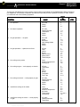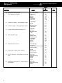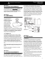
1
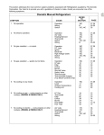
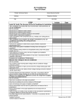
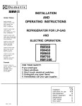
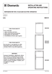
Foreword
This service manual is the result of the
dedication of The Dometic Corporation and
its engineers in giving service people the
necessary instruction for making accurate
analyses of certain conditions. Provided is
a diagnostic chart leading a qualified
mechanic into the service manual pages to
locate and solve symptoms which may
occur. Dometic has continued its
commitment in providing service people
with this, the most up-to-date information
about servicing Dometic RV accessories.
Form No. 3 106930.005 2/96 (Replaces 05 1409 1/93)
CONTENTS
PAGE NO.
RM2604 & 2804 STD DIAGNOSTIC FLOW CHART . . . . . . 1
SECTION 1
AC VOLTAGE REQUIREMENTS . . . . . . . . . . . . . . . ..__._._........... . . . . . . . . . . . . . . . . . . . . . . . . . . . . . . . . . . . .
3
SECTION 2
AC COMPONENTS
2.1 Heating Element . . . . . . . . . . . . . . . . . . . . . . . . . . .._............................................. 3
2.2 Thermostat . . . . . . . . . . . . . . . . . . . . . . . . . . . . . . . . . . . . . . . . . . . . . . . . . . . . . . . . . . . . . . . . . . . . . . . . . . . . . . . . . . 3
SECTION 3
DC VOLTAGE REQUIREMENTS . . . . . . . . . . . . . . . . . . . . . . . . . . . . . . . . . . . . . . . . . . . . . . . . . . . . . . . . . . . . . . . . . . . . . . 3
SECTION 4
DC COMPONENTS
4.1 Switch . . .._.............._........................_......................_......_.............. 3
4.2 I niter . . . . . . . . . . . . . . . . . . . . . . . . . . . . . . . . . . . . . .._...._.._.......................................... 4
4.3 I!lectrode
e ....... . .. . . . . . . . . . . . . . . . . . . . . . . . . . . . . . . . . . . . . . . . . . . . . . . . . . . . . . . . . . . . . . . . . . . . . . . . . . . .
4.4 High Volta e Cable . . . . . .._..................._.......................................... :
4.5 Door Switcc\ . . . . . . . . . . . . . . . . . . . . . . . . ..__......._._.........__..._...___...........___........ 5
4.6 Relay .._...................._.._._....................._._.........._................._.........
5
4.7 Heating Element . . . . . . . . . . .._......_.........._....._.......___........................... 5
SECTION 5
LP GAS REQUIREMENTS . . . . . . . . . . . . . . . . . . . . . . . . . . . . . . . . . . . . . . . . . . . . . . . . . . . . . . . . . . . . . . . . . . . . . . . . . . . . . . . . 5
SECTION 6
LP GAS COMPONENTS
Shut-Off Valve.. ...........................................................................
::: Filter.. ..........................................................................................
Thermostat.. ................................................................................
iii:: By-pass Screw ............................................................................
Safety Valve ...............................................................................
i:: Thermocouple .............................................................................
Burner .........................................................................................
Flue Baffle ...................................................................................
6:9 Flue Cap .....................................................................................
6.10 Flue Tube ....................................................................................
6.11 Orifice .........................................................................................
:.z
6
6
6
6
7
7
7
7
7
7
7
SECTION 7
WIRING
7.1
7.2
External Wiring . . . . . . . . . . . . . . . . . . .._....___..._............._..._._._.._._._......_........ 7
Internal Wiring . . . . . . . . . . . . . . . . . . . . . . . . . . . . . . . . . . . . . . . . . . . . . . . . . . . . . . . . . . . . . . . . . . . . . . . . . . . . . 8
SECTION 8
OTHER
Leveling.. ..................................................................................... 9
Ventilation ................................................................................... 9
Air Leaks ................................................................................... 10
Door Position.. ........................................................................... 10
Ambient Temperature.. .............................................................. 10
Coolin Unit.. ............................................................................. 11
Food 2tora e ............................................................................ 11
High Humi dityy ............................................................................ 11
Interior Liner Seal to Frame ....................................................... 11
Dometic® RM2604/2804
Refrigerators
DIAGNOSTIC SERVICE MANUAL
This program will address the most common system problems associated with the RM2604/2804 Manual Refrigerators supplied by The Dometic Corporation. Our intent is to provide you with a guideline of checks to make, should
you encounter one of the following symptoms.
SYMPTOM
CAUSE
REFER
TO
SECTION
DC Volts
Wiring
Switch
3
7
4.1
2. No electric operation.
AC Volts
Heating Element
Thermostat
Switch
Wiring
1
2.1
2.2
4.1
7.2
3. No gas operation — no spark.
DC Volts
Igniter
Electrode
High Voltage Cable
Switch
Wiring
3
4.2
4.3
4.4
4.1
7.2
4. No gas operation — sparks but no flame.
LP gas
Filter
Orifice
Burner
Shut-off Valve
Safety Valve
Thermocouple
5
6.2
6.11
6.7
6.1
6.5
6.6
5. No cooling on any mode.
Level
Ambient Temperature
Cooling Unit
8.1
8.5
8.6
6. No cooling on gas — cools properly on electric.
LP Gas
Thermostat
Filter
Orifice
Burner
Flue Baffle
Flue Tube
5
6.3
6.2
6.11
6.7
6.8
6.10
7. No cooling on electric — cools properly on gas.
AC Volts
Heating Element
Thermostat
Switch
Wiring
1
2.1
2.2
4.1
7.2
8.
Insufficient cooling on all modes.
Level
Ventilation
Ambient Temperature
Air Leaks
Thermostats
Cooling Unit
8.1
8.2
8.5
8.3
2.2 & 6.3
8.6
9.
Insufficient cooling on electric — cools properly
on gas.
AC Volts
Heating Elements
Thermostat
1
2.1
2.2
1.
No operation.
STEP
1
Diagnostic Service Manuals
Dometic® RM2604/2804
Refrigerators
SYMPTOM
2
DIAGNOSTIC SERVICE MANUAL
CAUSE
REFER
TO
SECTION
10.
Insufficient cooling on gas.
Cools properly on electric.
LP Gas Pressure
Thermostat
Filter
Orifice
Burner
Flue Baffle
Flue Tube
5
6.3
6.2
6.11
6.7
6.8
6.10
11.
Freezes on electric – cools properly on gas.
Thermostat
Wiring
2.2
7.2
12.
Freezes on gas – cools properly on electric.
Bypass Screw
Thermostat
6.4
6.3
13.
On gas mode, sparks while flame is lit.
Electrode
LP Gas
Bypass Screw
Filter
4.3
5
6.4
6.2
14.
Won't stay lit on gas.
LP Gas
Safety Valve
Thermocouple
Flue Baffle
Flue Cap
Orifice
Burner
5
6.5
6.6
6.8
6.9
6.11
6.7
15.
Rapid formation of frost.
Food Storage
Air Leaks
Interior Liner Seal to Frame
High Humidity
8.7
8.3
8.9
8.8
16.
Interior light on when door is closed.
Wiring
Door Switch
Door Position
7.2
4.5
8.4
17.
No DC operation – cools properly on AC and
gas.
DC Volts
Heating Element
Switch
Wiring
Relay
3
4.7
4.1
7.2
4.6
18.
Insufficient cooling on DC– cools properly on
AC and gas.
DC Volts
Heating Element
Relay
3
4.7
4.6
STEP
Dometic® RM2604/2804
Refrigerators
DIAGNOSTIC SERVICE MANUAL
SECTION 1
AC VOLTAGE REQUIREMENTS
The refrigerator is a 120-volt AC, 60 Hz appliance. The
proper operating range is 100 to 132 volts. Check the
AC volts at the receptacle where the refrigerator is
attached. Voltage is outside of the proper operating
range, correct the power source problem.
SECTION 2
AC COMPONENTS
the refrigerator. The operational range is 10.5 to 15 volts
DC. Connecting the refrigerator to an unregulated
converter can result in improper operation of the refrigerator. Check for proper voltage at the terminal block or
blocks at the back of the refrigerator. If power is outside
the operational range, correct the power supply problem.
The power supply to the refrigerator must be fused. The
interior light and igniter must be on a separate circuit and
will draw about 1 amp at 12 volts DC. The DC heating
element (on 3-way models only) will draw 18 amps at 12
volts DC. The maximum fuse size is 25 amps for the
RM2604 and RM2804.
2.1 HEATING ELEMENT
The heating element is
designed to deliver a
predetermined amount of
heat to the cooling unit.
To check a heating
element, remove the
heater leads from the
terminal block and
measure for proper
resistance across the
two leads with a properly
calibrated ohm meter. This check is to be done with the
heating element at room temperature. The proper ohms
for RM2604 is 48 and RM2804 is 44 with a tolerance of
ten percent. If the resistance is outside the tolerance
range, replace the heating element.
COVER
MANUAL GA S
SHUTOFF VA LVE
3-WAY ONL Y
3 P RONG P LUG
FOR 120V A C
ALL UNIT S
TERMINAL BL OCKS
12 V olts
DC
Heater
12 V olts
DC
Reigniter
Lamp
2.2 THERMOSTAT
It is an electric only thermostat. On 2-way models it
controls the AC heating element. On 3-way models it
controls the DC heating element as well as the AC
heating element. The thermostat regulates the cabinet
temperature by making and breaking the heat source
circuit. The internal mechanism breaks contact (continuity) when adequate cabinet temperature has been
reached. Check the thermostat for continuity or use a
jumper wire with insulated clips and bypass the thermostat.
NOTE: Care should be used. Do not short to thermostat
casing. Also remove the jumper after testing is completed.
If the above test allows the refrigerator to operate,
replace the thermostat.
SECTION 3
DC VOLTAGE REQUIREMENTS
For the refrigerator to operate the interior light, igniter
(gas mode) and DC volt operation (3-way models only),
DC voltage must be supplied to the terminal block or
blocks (2 terminal blocks on 3-way models) at the rear of
SECTION 4
DC COMPONENTS
4.1 SWITCH
This is the switch that selects the mode of operation
(120 volt AC, gas and 12 volt DC). It is also a circuit
interrupter for each mode of operation on the refrigerator. When the customer selects either AC, gas or DC (3way models only) operation, the selector switch directs
electricity first to the interior light and the thermostat and
on to the heating element or the igniter for gas mode.
When this switch is turned off, the AC or DC circuit is
interrupted. To check the switch in the AC mode,
continuity should exist between these terminals: 1 to 1A,
2 to 2A and 7 to 7A. To check the switch in the gas
mode, continuity should exist between these terminals: 4
to 4A and 7 to 7A.
To check the switch in the DC mode (on 3-way models
only), continuity should exist between these terminals: 5
to 5A, 6 to 6A and 7 to 7A.
NOTE: To do a continuity check, first be sure all power
is disconnected or off to the refrigerator. Second,
remove all wires from the switch. After the check, be
3
Dometic® RM2604/2804
Refrigerators
DIAGNOSTIC SERVICE MANUAL
sure switch is wired properly per the wiring diagram (See
Sec. 7.2).
When the switch is in the off position a continuity reading
SHOULD NOT be indicated on any terminals. If the
above test results are correct, DO NOT REPLACE the
switch. If any one of the above tests are not correct
REPLACE the switch.
sound. If not, replace the igniter. Next, with the igniter
producing spark, set the meter on 20 volts DC or lower
scale, connect meter leads to L and ground terminals on
the igniter. The meter should read a pulsating voltage. If
not, replace the igniter.
If all of the previous checks are correct, the igniter is
+Term.Ign.Lamp Term. Block
Thermostat
Thermostat
+Term. on Igniter
AC line
AC Neutral
HIGH VOLTAGE
Interior Light
Circuit DC Mode
Gas Mode
AC Mode
7
6 5 4
7a 6a 5a 4a
2
1
2a 1a
AC Mode
Gas Mode
DC Mode
Interior Light Circuit
7
6 5 4
7a 6a 5a 4a
2
1
2a 1a
AC Heater
Thermo+Reigniter-Lamp
Term.
stat
#30 Term.on Relay (+
#86 Term. on
Door Switch
4.2 IGNITER
The igniter is an electronic device that produces high
voltage to create a spark at the burner, only on gas
mode. It also produces an increased DC voltage at the L
terminal which is directed to the indication lamp each
time a spark is produced. First, check that the switch is
in the gas mode and is completing the circuit (See Sec.
4.1). Next, verify proper voltage at the positive (+) and
ground (-) terminals of the igniter. The reading should be
within one volt of incoming voltage at the igniter and
lamp terminal block. A voltage drop of more than one
volt would indicate a loose connection (See Sec. 7.2).
No voltage would indicate an open circuit, check switch
(See Sec. 4.1), wiring (See Sec. 7.2) and DC voltage
requirements (See Sec. 3).
good, DO NOT REPLACE. The pulsating voltage allows
a lamp to illuminate on the front of the refrigerator to
advise the customer spark has been produced. To check
the lamp, first, verify it is wired correctly. Next, verify the
lamp receptacle is receiving the signal, if so, and lamp is
not illuminating (flashing), replace the lamp.
NOTE: Do not supply DC power to the lamp. It will not
illuminate with normal DC power. For the lamp to
illuminate it must receive an increased DC signal.
4.3 ELECTRODE
To check the electrode, first do a visual inspection for
cracks or breaks on the ceramic insulator. Also, verify
the mounting bracket is attached properly to the electrode. If either of the above conditions are found, replace
the electrode. Next, check the spark gap. It must be set
at three sixteenths (3/16) of an inch and the tip of
electrode above the slots in the burner.
ELECTRODE
TIP
HIGH VOLTAGE
3/16"
BURNER
NOTE: If igniter (See Sec. 4.2) and high voltage cable
(See Sec. 4.4) are good and there is no spark at the tip
of the electrode, REPLACE THE ELECTRODE.
4.4 HIGH VOLTAGE CABLE
Next, disconnect DC power at the igniter, lamp terminal
block. Remove high voltage cable from igniter. Reconnect DC power, the igniter should produce a sparking
4
NOTE: Be sure switch (See Sec. 4.1) and igniter (See
Sec. 4.2) are good before checking the high voltage
cable and the switch is in the gas mode.
Dometic® RM2604/2804
Refrigerators
DIAGNOSTIC SERVICE MANUAL
To check the high voltage cable, first disconnect DC
power at the igniter, lamp terminal block. Next, disconnect high voltage cable from electrode. Then reconnect
DC power to the terminal block. If sparking starts, cable
is good, DO NOT REPLACE, check the electrode (See
Sec 4.3). If no sparking, disconnect DC power at the
igniter, lamp terminal block and then disconnect high
voltage cable at the igniter. Reconnect DC power to the
terminal block. If sparking sound from igniter, replace the
high voltage cable.
between terminals 85 and 87. If no voltage is present,
the relay is defective, replace it.
87
85
4.5 DOOR SWITCH
The door switch is an open switch when the switch arm
is depressed (interior light should be off). When the
refrigerator door is open, the switch is closed (interior
light should be on). Check that the switch assembly is
properly aligned and that it is not broken. Check the
switch assembly for continuity. When the switch arm is
depressed there should not be continuity. When the
switch arm is NOT depressed there should be continuity.
If any of the checks are incorrect, replace the switch.
4.6 RELAY (3-WAY MODELS ONLY)
The relay controls the circuit to the DC heating element.
The load (amps) of the DC heating element goes
through the relay.
To check the relay, first verify the
selector switch is on DC mode
(See Sec. 4.1) and the
thermostat (See Sec. 2.2) is
NOT completing the circuit.
Next, verify voltage is present
between terminals 85 and 30. If
voltage is not present, check
wiring to both terminals. (See
Sec. 7.2)
85
30
HEATING ELEMENT
(3-WAY MODELS ONLY)
The heating element is designed to deliver a predetermined amount of heat to the cooling unit. Check the
heating element with ohms resistance using a properly
calibrated ohm meter. This check is to be done with the
element at room temperature. The proper ohms for
RM2604 and RM2804 DC heating element is .67 with a
tolerance range of ten (10) percent. If the heating
element is outside the
tolerance range, replace it.
NOTE: It will take a very
precise ohm meter to
accurately read this
measurement. If a precise
ohm meter is not available,
a continuity reading will
indicate an open or complete circuit. If an open
circuit is the test result,
replace the element.
87
85
Next, check for voltage
between terminals 85 and 87.
If voltage is present, the relay
is defective and needs to be
replaced.
SECTION 5
LP GAS REQUIREMENTS
Second, verify the selector switch is
on DC mode (See Sec. 4.1) and the
thermostat (See Sec. 2.2) is completing the circuit.
Next, verify voltage is present
between terminals 85 and 86.
If no voltage is present, check
wiring and connections (See
Sec. 7.2).
4.7
The LP gas pressure to the refrigerator should be 11
inches water column with half of all BTU’s of the RV
turned on. With all other appliances turned off, the
pressure to the refrigerator should not exceed 12 inches
water column. To check the gas pressure when the
refrigerator is operating, there is a pressure test housing
located just prior to the orifice.
85
86
Next, if voltage is present,
between 85 and 86 terminals,
then voltage should be present
PRESSURE T EST HOUSING
5
Dometic® RM2604/2804
Refrigerators
DIAGNOSTIC SERVICE MANUAL
SECTION 6
6.3 THERMOSTAT
LP GAS COMPONENTS
On the LP gas mode, full line pressure is directed
through the thermostat to the burner until the thermostat
senses that the refrigerator cabinet has reached proper
cooling temperature. At that time an internal valve closes
and redirects the gas flow through the by-pass screw.
This reduces the amount of LP gas going to the burner
assembly. The gas flow remains in this “by-pass” mode
until the thermostat senses that the refrigerator cabinet
needs more cooling. Again, the thermostat directs LP
gas flow through the thermostat at full line pressure until
the cabinet temperature is sufficient. The thermostat is
calibrated by the manufacturer so that at mid-range the
cabinet temperature should be approximately 40 degrees Fahrenheit. To check the calibration of the
thermostat, place a container of water in the cabinet of
the refrigerator and operate at mid-range setting until the
thermostat is satisfied. Then, check the temperature of
the water. It should be approximately 40 degrees. We do
not recommend any calibration in the field. If calibration
is not correct, replace the thermostat. To check the
thermostat for proper gas flow, set the thermostat to
maximum and check the gas pressure at the pressure
test port. It should be line pressure, between 11 to 12
inches water column. If you have less than 11 inches of
water column pressure, the next step would be to shut
off the gas supply and remove the by-pass screw. Then
install a by-pass screw that does not have the small oring on it. Next, turn on the gas supply and take a
reading. If the manometer now reads 11 inches of water
column, the thermostat is defective and must be replaced. If the by-pass screw test shows no change in
pressure, the problem lies in the filter (See Sec. 6.2), the
shut-off valve (See Sec. 6.1) or the gas supply (See
Sec. 5). Shut off the gas supply, remove the by-pass
screw, replace it with a proper one that has an o-ring
and turn the gas on.
6.1 SHUT-OFF VALVE
It is the valve where the incoming LP gas supply is
attached. This valve is direct coupled to the selector
switch. When the selector switch is turned to the electric
mode, the shut-off valve is automatically closed. When
this same switch is turned to the LP gas mode, the valve
opens and allows gas flow and the electric circuit to the
heating elements is also automatically interrupted. To
check the shut-off valve, remove and inspect for any
obstructions.
COVER
MANUAL GA S
SHUTOFF VA LVE
3-WAY ONL Y
3 P RONG P LUG
FOR 120V A C
ALL UNIT S
TERMINAL BL OCKS
12 V olts
DC
Heater
12 V olts
DC
Reigniter
Lamp
6.2 FILTER
A filter is located in the inlet fitting to the gas thermostat.
It protects the internal valve portion of the thermostat by
collecting any particles and/or oil that could get into the
LP gas line. The filter can become saturated and cause
a restriction to gas flow. This could cause a lack of
cooling on gas mode. If you suspect a restriction, first
verify the thermostat (See Sec. 6.3) and by-pass screw
(See Sec. 6.4) are good. If these components are good,
remove the filter and replace with a new one if proper
gas pressure is supplied to the refrigerator and you
cannot get proper gas pressure at the pressure test
housing.
LINE
SHUTOFF VA LVE
FILTER
COUPLING
GAS
THERMOSTAT
6
NOTE: Check for leaks with an approved LP gas leak
solution whenever any part of the gas system has been
worked on.
6.4 BY-PASS SCREW
The by-pass screw is a small brass screw located on
any Dometic gas thermostat that regulates gas flow in
the low flame mode. There are three common sizes of
this screw: S-17 (350 BTU), S-14 (325 BTU) and S-11
(300 BTU). To check the by-pass screw, connect a
manometer at the pressure test housing. The pressure
on low flame mode should be 3 to 5 inches water
column. Above 5 inches water column on low flame
mode could cause an over-cooling situation. The bypass screw used on the RM2604 and the RM2804 is S14.
Dometic® RM2604/2804
Refrigerators
DIAGNOSTIC SERVICE MANUAL
6.5 SAFETY VALVE
6.9 FLUE CAP
The safety valve is an assembly that shuts off the supply
of LP gas to the burner if the flame goes out for any
reason. This is to ensure that a concentration of unburned gas does not accumulate in the refrigerator vent
area. To check the safety valve, use a known good
thermocouple (See Sec. 6.6) and install into the safety
valve. Next, supply flame to the tip of the thermocouple
for 2 to 3 minutes while holding in on the safety valve
stem. Next, remove flame from thermocouple tip and
release safety valve stem. The safety valve should hold
in for at least 30 seconds. If it releases earlier than 30
seconds, replace the safety valve.
The flue cap is located at the top
of the flue tube and is attached
with a screw. It must be properly
attached or flame outage could
occur.
6.6 THERMOCOUPLE
The thermocouple is a component extending above the
burner assembly so the tip is in the path of the flame. It
will produce 14 to 30 millivolts DC in normal operation.
To check the thermocouple, use a known good safety
valve (See Sec. 6.5) and attach to the thermocouple.
Next, supply flame to the tip of the thermocouple for 2 to
3 minutes while depressing the safety valve. Remove
the flame and release the safety valve. The valve should
hold for at least 30 seconds. If it does not hold the safety
valve open for 30 seconds, replace the thermocouple. If
it does hold for 30 seconds or more, the thermocouple is
good, do not replace it.
NOTE: Be sure the tip on the thermocouple is clean.
6.7 BURNER
The burner is a slotted metal tube located below the flue
tube on the cooling unit. It should be level and the slots,
in the burner, should be directly below the flue tube. The
burner should be cleaned periodically, at least once a
year. To clean the burner, remove from the refrigerator
and check for any foreign residue that could cause a
deflection of the gas flow or the flame. Next, soak the
burner in an alcohol based solvent and allow to air dry.
After cleaning, reinstall in the refrigerator.
6.8 FLUE BAFFLE
The flue baffle is designed to concentrate the heat, from
the gas flame, at a certain area of the flue tube. It should
be cleaned periodically, at least once a year. To clean,
remove from the flue tube and check for any damage,
then clean thoroughly. The length of the flue baffle
assembly (flue baffle and wire) for the RM2604 is 31-9/
16 inches and for the RM2804 is 37-1/8 inches. The flue
baffle itself for the RM2604 is 3/4 inch wide and 5-1/4
inches long, for the RM2804 is 3/4 inch wide and 6
inches long. The proper baffle position for the RM2604 is
1-5/8 inches from the burner to the bottom of the baffle;
for the RM2804 is 1-3/4 inches from the burner to the
bottom of the baffle.
6.10 FLUE TUBE
The flue tube is a component of
the cooling unit. It must be
cleaned periodically, at least
once a year. To clean, remove
flue cap and flue baffle, then cover the burner and
clean by using a flue brush. Dometic Part Number
0151404001. If the flue tube becomes coated with scale
or residue from combustion of LP gas, the efficiency of
gas operation decreases.
NOTE: After cleaning be sure to reinstall the flue baffle
and flue cap.
6.11 ORIFICE
The orifice is a small brass fitting that has a ruby membrane that is laser beam drilled and is mounted on the
gas line just prior to the burner. The orifice should be
cleaned periodically, at least once a year, by using an
alcohol based solvent and allowing to air dry. Never use
a drill bit or jet tip cleaner to clean any orifice as these
devices will damage the factory machined part and
create a potentially dangerous condition. The correct
orifice for the RM2604 is number 53 jet, for the RM2804
is number 58 jet.
NOTE: Always use the proper orifice. Never use a larger
orifice as this could cause a lack of cooling problem.
SECTION 7
WIRING
7.1 EXTERNAL WIRING
1. 120 volts AC connection: The refrigerator is
equipped with a three prong (grounded) plug for
protection against shock hazards and should be
plugged directly into a properly grounded three prong
receptacle. Do not cut or remove the grounding prong
from this plug.
2. 12-volt connection for igniter and interior light:
The connection is made to the terminal block marked
12 volts DC REIGNITER-LAMP. The interior light and
the igniter must be connected to a separate battery
circuit and will draw about 1 amp at 12 volts DC.
3. 12-volt DC connection for heater (3 -way models
only): This connection is made to the terminal block
marked DC VOLT HEATER. The refrigerator must be
connected to the battery circuit with two wires of
7
Dometic® RM2604/2804
Refrigerators
DIAGNOSTIC SERVICE MANUAL
adequate capacity to avoid voltage drop. The wire
gauge should be chosen with consideration to the
wire length in accordance with the following table.
RM2604
RM2804
Int. Light Only
10
17
17
55
8
27
27
85
12V DC
HEATER
RELAY
MAXIMUM TOTAL CONDUCTOR WIRE LENGTH IN FEET
AWG
SWITCH KEY
BREAKER
POINT
IGNITION
COIL
REIGNTER A ND
INTERIOR L IGHT
BATTERY
(RV)
Do not use the body or chassis of the vehicle as a
substitute for either of the two conductors. No other
electrical equipment or lighting should be connected to
the refrigerator circuit. The refrigerator will draw 18 amps
at 12 volts DC.
BATTERY
(ENGINE)
7.2 INTERNAL WIRING
DO NOT OPERATE THE REFRIGERATOR ON 12VOLT WHEN THE VEHICLE IS PARKED. THE CUSTOMER WILL RUN OUT OF BATTERY IN A RATHER
SHORT TIME. IF POSSIBLE, THE INSTALLATION OF
A 12-VOLT OPERATED REFRIGERATOR SHOULD
BE COMPLETED WITH A RELAY MOUNTED EITHER
IN THE TOW VEHICLE OR IN THE RECREATIONAL
VEHICLE. THIS RELAY WILL AUTOMATICALLY CUT
OUT THE REFRIGERATOR WHEN THE MOTOR IS
STOPPED.
Check all wires and the connectors to ensure a proper
and tight connection. Also verify the refrigerator is wired
per the wiring diagram for the model you are working on.
(See wiring diagram below and on the next page.)
RM2604 & RM2804 2-WAY 120 VOLTS
G
H
12 V OLTS DC
120 V OLTS A C
1
G
2
7
4
7
2 1
A
L
A
C
2
1a
7a
K
2a
4
4
B
4
7a 4a
H
E
F
4a
I
4
1
2
1
2
2
1
120 V OLTS A C
D
1
N
L
4
3
1
8
2
1
E
1
A
C TERMINAL BL OCK
D TERMINAL BL OCK
E
2
2
I
J
2a
1a
B
D
N
L
HEATER
F REIGNITER
C
1 WHITE
2 BLACK
3 GREEN
4 GREEN/YELLOW
A SWITCH
B THERMOSTAT
120 V OLTS A C
F
1
C
12 V OLTS DC
REIGNITER
LAMP
G LAMP
H DOOR SW ITCH
I
INDICATION L AMP
J TERMINAL ST RIP
K
ABSORPTION UNIT
L BRACKET
Dometic® RM2604/2804
Refrigerators
DIAGNOSTIC SERVICE MANUAL
RM2604 & RM2804 3-WAY 12/120 VOLTS
J K
120 V OLTS
DC
12VOLTS
AC
2
1
76 5 4
1
2
B
6a
4
1
F
A
5a
B
2a
H
1a
B
E
86
87
85
30
N
L
H
4
2
12 V OLTS
DC
HEATER
N
120 V OLTS A C L
12 V OLTS DC MODE
1
2
4
1
J
2
C
1
1
D
12 V OLTS DC
REIGNITER
LAMP
1
I
7
E
4
A
4
WHITE
BLACK
GREEN
GREEN/YELLOW
G HEATER
H RELAY
4
3
1
1
2
7a
4a
8.1 LEVELING
Leveling is one of the requirements for proper operation
with absorption refrigerators. The absorption design
utilizes no mechanical pumps or compressors to circulate the refrigerant within the system, so proper leveling
must be maintained to provide the correct refrigerant
flow. Without proper leveling, refrigerant within the
cooling unit will collect and stagnate at certain areas.
Without proper refrigerant flow, the cooling process will
stop. The RM2604 and RM2804 has a type of cooling
unit that utilizes an enclosed pump tube surrounded by a
solution to protect the assembly. To insure proper
leveling with these models, the vehicle needs to be
leveled so it is comfortable to live in. (No noticeable
sloping of floor or walls). When the vehicle is moving,
leveling is not critical as the rolling and pitching movement of the vehicle will pass to either side of level,
keeping the refrigerant from accumulating in the piping.
J LAMP
K
L
M
N
O
H
OTHER
REIGNITER
I
I
L
I
SECTION 8
A SWITCH
B THERMOSTAT
C TERMINAL BL OCK
D TERMINAL BL OCK
E TERMINAL BL OCK
F HEATER
K
L
1
2
3
4
2
A
2
1
4
2
G
5
2a 1a
D
2
6
2 1
A
7a 6a 5a 4a
120 V OLTS A C MODE
12 V OLTS DC MODE
DOOR SW ITCH
INDICATION L AMP
TERMINAL ST RIP
ABSORPTION UNIT
BRACKET
of the refrigerator. The refrigerator extracts heat from
the interior of the refrigerator cabinet and dissipates the
heat out through the vent system. In a proper installation
there should be as little open space as possible surrounding the sides and top of the refrigerator to achieve
proper air flow. All potential dead air pockets should be
blocked or baffled to insure that heat won’t be trapped in
these spaces and reduce efficiency. In addition, the
cooling unit should be at least one half (1/2) inch from
the nearest surface made of combustible material.
NOTE: Refrigerators should be installed in accordance
with appropriate installation instructions received with
the refrigerator.
8.3 AIR LEAKS
0" CLEARANCE
FROM SIDE OF
CABINET
1/2" FROM
COMBUSTIBLE
MATERIALS
8.2 VENTILATION
Ventilation is one of the requirements for proper cooling
unit operation. The coach vent system must be able to
provide a way to direct the hot air, produced by the
action of the cooling unit, out away from the installation
PATH OF
AIR FLOW
9
Dometic® RM2604/2804
Refrigerators
DIAGNOSTIC SERVICE MANUAL
Check the gasket on the doors to be sure of a positive
air seal. A simple method to check gaskets is to close
the door on a dollar bill, then pull the dollar bill out. If no
resistance is felt, the gasket is not sealing properly. This
should be done on all four sides of the door. If a gasket
is not sealing properly, first warm the gasket material
with a hair dryer.
tioned to re-orient the door. Turn the refrigerator on its
side to gain access to the two front base screws. Loosen
both screws slightly. Reposition the base until the door is
re-oriented. Re-tighten the base screws while holding
the base in its new position.
DO NOT OVERHEAT
AS YOU CAN MELT THE MATERIAL.
Then close the door and the magnetic strip should pull
the gasket to the metal frame. Leave door closed until
the material has cooled. Then re-check for a positive
seal. If a positive seal cannot be achieved, replace the
door gasket. Also check that the cooling unit is installed
properly. The cooling unit’s foam block, the portion that
surrounds the evaporator coils, must be flush to the
cabinet at the back of the refrigerator and have a
positive seal. If the cooling unit is not installed properly,
remove and install properly.
NOTE: Air leaks will cause insufficient cooling as well as
rapid formation of frost.
BASE
FRONT
8.4 DOOR POSITION
The door position can be checked by observing any
misalignment of the door in relation to the frame.
BASE
SCREWS
To correct an
SMOOTH FIT,
PROPER SEAL
NOTE: Improper position of the lower door can cause
the interior light to stay on when door is closed.
8.5 AMBIENT TEMPERATURE
alignment of the door, loosen the hinge screws slightly,
and re-orient the door in the proper position. Hold the
door in its new position and carefully retighten the hinge
screws.
If the door needs more adjustment than is available
through the hinge adjustment, the base can be reposi10
This is the temperature surrounding the recreational
vehicle, as well as the temperature of air at the back of
the refrigerator. As the ambient temperature increases,
the air temperature in the area of the cooling unit
increases. Improper venting at this point, will cause the
cooling unit to have reduced efficiency.
Dometic® RM2604/2804
Refrigerators
DIAGNOSTIC SERVICE MANUAL
8.6 COOLING UNIT
The cooling unit is a self-contained, hermetically sealed
set of coils where the refrigeration process takes place.
The chemicals involved in the cooling process include
hydrogen, ammonia, water and a rust inhibiting agent.
There are no repairs recommended on the cooling unit.
If it is defective, replace with a new cooling unit. To
check the cooling unit, first verify the AC heating element is good (See Sec. 2.1). Then place approximately
one gallon of water inside the refrigerator and place a
thermometer in one of the containers of water. Next,
supply 115 volts direct to the AC heating element and
operate for at least 12 hours. Then check the temperature on the thermometer. It should be at 45 degrees or
lower depending on test conditions (See ambient temperature Sec. 8.5). If so, the cooling unit is good. If the
temperature of the water is above 45 degrees, replace
the cooling unit.
lettuce, etc., should be covered to retain their crispness.
NEVER PUT HOT FOOD INTO THE REFRIGERATOR.
To reduce frost formation in and on the freezing compartment, cover stored liquids and moist foods and do
not leave the door open longer than necessary. When
the refrigerator is heavily loaded, it takes a longer time
for refrigerator temperatures to lower, also increasing
the ice making time. A very heavy load may also cause
defrosting.
8.8 HIGH HUMIDITY
High humidity may cause a small amount of condensation to form on the frame of the refrigerator. In some
cases it can develop to such a degree that it will run off
the frame. As the humidity is reduced, the sweating will
decrease. High humidity can also be a factor in rapid
formation of frost.
8.7 FOOD STORAGE
Proper refrigeration requires free air circulation within the
food storage compartment. Restricted air circulation
within this compartment will cause higher cabinet
temperatures. To remedy this situation, simply rearrange
your foodstuffs. It is also essential that the shelves are
not covered with paper or large storage containers.
Always remember to allow for proper air circulation.
Odorous or highly flavored foods should always be
stored in covered dishes, plastic bags or wrapped in foil
or waxed paper to prevent food odors. Vegetables,
8.9 INTERIOR LINER SEAL TO FRAME
There is a seal that is applied to the liner in the area
where the metal frame makes contact with the interior
liner. If this seal is incomplete, cold air can migrate out
to the metal frame. If this happens, condensation could
form on the frame and could promote rapid formation of
frost. If you suspect an improper seal, apply a small
bead of silicone all the way around the perimeter where
the frame meets the interior liner.
11