1
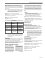
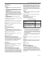
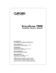
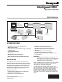
Intelliguard 9000™
SECURITY SYSTEM
SPECIFICATION DATA
I9000 CONTROL UNIT
AND POWER SUPPLY
PRO 9000
(SOFTWARE
NOT INCLUDED)
NOTE: PRO 9000 MAY
ONLY BE CONNECTED
TO ONE I9000 CU AT A TIME.
EBI
RS-232
(RS-485 WITH RRI)
AREA
KEYPAD
MULTIPLE
OUTPUT MODULE
RS-485
HALL EFFECT
DOOR SWITCH
I9000 CONTROL UNIT
AND POWER SUPPLY
BIC-2
INPUT MODULE
CONTROL
CENTER 2 KEYPAD
BIC-6
INPUT/OUTPUT MODULE
RS-485 TO
I9000 DEVICES
M14456A
SYSTEM FEATURES
• Adaptable for a wide range of applications.
• Multiple area controls.
• False alarm reduction minimizes costly, unnecessary
emergency calls.
• Cost effective protection.
• Easy-to-use.
• Multiple regulatory agency listings.
• Meets High Security UL Grade AA requirements.
APPLICATION
The Intelliguard 9000™ (I9000) is a protection system
designed to detect intrusions and other critical conditions
when used with the Enterprise Buildings Integrator™ (EBI).
The I9000 monitors multiple areas, receiving input and
providing localized reporting and control. A single I9000
Control Unit can simultaneously monitor many different
building areas with high security door sensors.
I9000 hardware includes:
— 8003-217 Remote Intelligent Power Supply (RIPS).
— 8003-220 Area Keypad (KID).
— 8003-238 6-Input Concentrator (BIC-6).
® U.S. Registered Trademark
Copyright © 2004 Honeywell International Inc.
All Rights Reserved
—
—
—
—
—
—
—
—
8003-242 2-Input Concentrator (BIC-2).
8003-277 Control Center 2 (CC2) Keypad.
8003-283 Hall Effect Door Switch IV (HEDS IV).
8003-284 2-Input Concentrator Hold-up Actuator
(BIC-2 HU).
8003-286 Multiple Output Module (MOM).
8003-321 RS-232 to RS-485 Interface (RRI).
8003-332 I9000 EBI/Orbix Control Unit (CU) in casing.
12-volt batteries.
IMPORTANT
The Multiple Output Module is currently not a CE
approved device. In countries requiring CE approval,
the installer should reconfigure one or more BIC-6
input/output devices as output devices.
Other compatible detectors and output devices can be added
to the system such as motion sensors, infrared sensors,
sound detectors, lights, sirens and buzzers.
The I9000 detects an abnormal situation with one of its
detection devices such as a HEDS IV, locates the alarm and
then sends that alarm signal to the Enterprise Buildings
Integrator™ (EBI). The EBI uses that signal to take the
necessary action. The I9000 can also activate a local alarm
output such as a siren, light, or buzzer when attached to the
system.
74-3035-2
INTELLIGUARD 9000™ SECURITY SYSTEM
All events are sorted by day and date and then recorded in an
event log.
Intelligent Switching Power Supply (ISP)
ISP FEATURES
• Red LED Communication Indicator is disabled if no
jumper is present on the ISP tamper input.
The I9000 recognizes a maximum of 99 users, plus one
reserved for service personnel, and five security levels with
individual identification numbers (ID) and passwords.
• Green LED AC On Indicator.
SPECIFICATIONS
• Switch selectable address (0, 1, 2, or 3). Learned using
CC2 or PRO9000.
Each component of the I9000 has the following temperature
and humidity requirements:
• Switch selectable programmable output mode (steady
or pulsing).
Temperature Ratings: 32°F to 120°F (0°C to 49°C).
• Status transmission (Low Battery, AC Fail, Tamper).
• RS-485 receiving and transmitting signals.
Humidity Ratings: 5% to 95% at 86°F (30°C) RH, noncondensing.
I9000 Control Unit
The Control Unit includes the
8003-295 Intelligent Switching
Power Supply (ISP) and the
8003-331 Intelligent
Communications Processor II
(ICP II). The I9000 Control Unit
supports up to 62 devices, 31
on each of two communication
ports, with 512 input points and
64 output points. The Control
Unit receives an intrusion
alarm signal from a BIC-6, BIC-2, or HEDS IV. The CU
processes the signal and sends it to the EBI, output devices,
or both. The EBI uses the signal to take the appropriate
action. The MOM, BIC-6 (configured for output), BIC-2,
BIC-2 HU, or ISP output activates any local alarms such as a
siren, light, or buzzer that are attached to the system.
The control unit supports up to eight ISPs, one of these is the
ISP contained in the I9000 Control Unit enclosure itself and
counts as one of the 62 devices. The other ISPs are located in
RIPs, one ISP per RIPS. Depending on the installation power
backup requirements, up to two batteries can be connected to
the ISP. When the ISP programmable output is used, two
batteries are recommended.
For added security, system configuration is only accessible
using the service technicians ID and Code with the control unit
in tamper alarm.
NOTE: Power for the ISP programmable switched output is
partly obtained from the standby batteries. Therefore, this output should be used to drive loads such
as sirens and bells for short durations (15 minutes
maximum). Otherwise the battery capacity will be
reduced and this will affect the total backup time
available for the devices connected to that ISP.
Standby Batteries:
Model: YUASA P/N NP7-12, or equivalent.
Electrical Ratings: 12V, 7 Ah.
Type: Sealed lead acid.
Quantity: Two, maximum.
Dimensions, maximum: 2-9/16 in. (65 mm) wide x 3-7/8 in.
(98 mm) high (including terminals), x 6 in. (152 mm) deep.
Weight: 6.17 lb (2.65 kg).
Intelligent Communications Processor II (ICP II)
ICP II FEATURES
• Enclosure tamper switch input.
• Two RS-485 ports for communicating with peripheral
devices (receiving and transmitting signals).
• One RS-232 port for communicating with an EBI
station, or for remote programming from a PC via
PRO9000 (receiving and transmitting signals).
Model: 8003-332 I9000 EBI/Orbix Control Unit.
Firmware:
8950-109: Supports the I9000 EBI/Orbix protocol (included).
8950-100: Only supports existing XSM installations.
• Red communication status LEDs for all three ports. To
save power, LEDs disabled when tamper normal.
NOTE: Firmware 8950-100 (SMP protocol) must be ordered
separately and field swapped at installation time.
Electrical Ratings:
Transformer: Must be connected to a non-switched electrical
circuit.
Type: Class II Energy Limiting.
Output Voltage: 16 Vac.
Output Current: 2.3A.
Power Rating: 37 VA.
74-3035—2
Electrical Ratings:
Operating Voltage: 13.6 Vac to 17.6 Vac.
ICP Power Consumption during AC failure: 20 mA at 13.8 Vdc
(maximum battery voltage). Add programmable output load
current to this value if the output is used.
Outputs: 2 x 400 mA maximum at 12.9 Vdc ± 4%. One programmable switched output at 1A, 12 Vdc.
2
• On-board independent battery backup for Real Time
Clock and data memory. Ten year battery life.
• Reports a loss of Real Time Clock operation to the EBI
(F/W 8950-109 only; must be programmed in I9000).
• Reports a loss in device communication (must be
programmed in I9000).
• Push button switch and yellow LED cold start
indicator.
Electrical Ratings:
Operating Voltage: 10 Vdc to 18 Vdc.
ICP II Power Consumption: 55.4 mA at 14.5 Vdc.
INTELLIGUARD 9000™ SECURITY SYSTEM
Wiring Connections: Table 1 describes the connections
between the I9000 CU and its input and output devices. Use a
RS-232 cable to connect the CU to the EBI. Use twisted pair
cable to connect the RS-485 CU ports to the I9000 input and
output devices.
NOTE: All devices should be equally divided among the two
RS-485 communication lines to maximize system
performance. See Control Center 2 Keypads and
Area Keypads sections for details.
Each I9000 CU supports a maximum of seven RIPS. The
control unit supports up to eight ISPs (four per RS-485 port),
seven in the RIPS (one per RIPS) and one located in the
I9000 control unit enclosure. Depending on the installation
power backup requirements, up to two batteries can be
connected to each ISP. When the programmable outputs are
used, two batteries are recommended for those respective
RIPS.
Features
Dimensions: 14-7/16 in. (367 mm) wide x 10-5/16 in. (262
mm) high x 3-1/8 in. (79 mm) deep.
• Same as ISP features except the tamper input is factory
wired to the RIPS enclosure tamper switch.
• When cover is closed, the red LED Communication
Indicator is automatically disabled to save power.
Weight: 8.66 lb (3.93 kg), without batteries.
Model: 8003-217 Remote Intelligent Power Supply (RIPS).
Approvals: UL, ULC, CE.
Transformer Electrical Ratings: Each RIPS must have its
own transformer connected to a non-switched electrical circuit.
Type: Class II Energy Limiting.
Output Voltage: 16 Vac.
Output Current: 2.3A.
Power Rating: 37 VA.
Enclosure: 0.06 in. (1.52 mm) cold rolled steel.
Table 1. I9000 CU Cable, Baud Rate Connections to Input,
Output Devices.
Designation
Application
COM1, COM2
I9000 CU and
peripherals
Electrical Interface RS-485
Cable
COM3
EBI Interface
RIPS Electrical Ratings:
Operating Voltage: 13.6 Vac to 17.6 Vac.
ISP Power Consumption During AC Failure: 20 mA at
13.8 Vdc (maximum battery voltage). Add programmable
output load current to this value if the output is used.
Outputs: 2 x 400 mA maximum at 12.9 Vdc ± 4%. One programmable switched output at 1A, 12 Vdc.
RS-232
Twisted Pair (two or Shielded Cable,
three pairs)
four conductors
Maximum Distance 3277 ft (999m)
75 ft (22m)
Baud Rate
4800 Baud
75-2400 Baud,
Programmable
Word Format
10 Bits (Start, 7
Data, Even Parity,
Stop)
12 Bits (1 Start, 8
Data, 1 Parity, 2
Stop)
NOTE: Device to CU wire gauge is 22 AWG. Voltage drops
due to load and cable length may require an increase
in conductor size to ensure devices remain within
operational limits.
Power Supply
The I9000 and the RIPS operate from 16 Vac, 50/60 Hz (37 to
40 VA) provided by a locally supplied power transformer. For
ULI installations, this is a Silent Knight model 9220
Transformer with Silent Knight model 4165 Enclosure or listed
equivalent. For ULC installations (Canada only), this is a
5660-051 Honeywell Transformer Assembly.
Remote Intelligent Power Supply
NOTE: Power for the ISP programmable switched output is
partly obtained from the standby batteries. Therefore, this output should be used to drive loads such
as sirens and bells for short durations (15 minutes
maximum). Otherwise the battery capacity will be
reduced and this will affect the total backup time
available for the devices connected to that ISP.
Standby Batteries:
Model: YUASA P/N NP7-12 or equivalent.
Electrical Ratings: 12V, 7 Ah.
Type: Sealed lead acid.
Quantity: Two maximum.
Dimensions: 2-9/6 in. (65 mm) wide x 3-7/8 in. (98 mm) high
(including terminals), x 6 in. (152 mm) deep.
Weight: 6.17 lb (2.65 kg).
Communication: RS-485 receiving and transmitting signals.
Enclosure: 0.06 in (1.52 mm) cold rolled steel.
A Remote Intelligent Power
Supply (RIPS) consists of an
I9000 enclosure containing the
8003-295 Intelligent Switching
Power Supply (ISP) without an
ICP II Control Board. The RIPS
is required when the installation
power requirements exceed the
available control unit power.
Dimensions: 14-7/16 in. (367 mm) wide x 10-5/16 in.
(262 mm) high x 3-1/8 in. (79 mm) deep.
Weight: 8.62 lb (3.91 kg).
Approvals: UL, ULC, CE.
3
74-3035—2
INTELLIGUARD 9000™ SECURITY SYSTEM
Control Center 2 Keypads
Features
• Serial numbered device—no address switch setting
required—learned through the KID Keypad in
conjunction with a CC2 Keypad or using PRO9000.
Each I9000 CU supports a
maximum of four Control
Center 2 (CC2) Keypads, two
per communication channel
maximum. Each CC2 displays
current system status and
allows local system control.
The operator can perform all
functions related to
programming, arming and
disarming any area at the CC2.
• Quick Reference guide (protruding from the top of the
KID) can be extended as required.
• Keypad insert can be used to identify the four
programmable LEDs at installation.
Model: 8003-220 Area Keypad.
Electrical Ratings:
Nominal Operating Voltage: 12 Vdc to 15 Vdc.
Operating Voltage: 10 Vdc to 18 Vdc.
Nominal Operating Current: 28.6 mA at 14.5 Vdc.
Features
• Automatically learned by the I9000 CU at power up.
• Can be programmed via DIP switch for no backlighting
or backlighting with auto shutoff after five minutes of
no activity.
• Tone volume programmable via DIP switch for Low or
High output.
• Supports four different addresses, programmable via
DIP switches.
Model: 8003-277 Control Center 2 Keypad.
Electrical Ratings:
Nominal Operating Voltage: 12 Vdc to 15 Vdc.
Operating Voltage: 10 Vdc to 18 Vdc.
Nominal Operating Current: 10 mA at 14.5 Vdc, no backlighting, (107 mA with backlighting).
Annunciation: Two line by 24 character LDC display with
backlighting. Backlighting can be disabled to conserve
power. A red LED and a tone give the user visual and audible keystroke feedback.
Keypad: Membrane keypad with 12 keys.
Communication: RS-485 receiving and transmitting signals.
NOTE: Area Keypads should be equally divided among the
two RS-485 communication lines to maximize system performance.
Enclosure: Plastic polycarbonate base, ABS plastic cover.
Dimensions: 6-7/8 in. (174 mm) wide x 4-3/16 in. (106 mm)
high x 1-1/4 in. (30 mm) deep.
Weight: 0.66 lb (0.30 kg).
Approvals: UL, ULC, CE.
BIC-6 Input Concentrator
Keypad: Membrane keypad with 20 keys.
Communication: RS-485 receiving and transmitting signals.
NOTE: Control Center 2 Keypads should be equally divided
among the two RS-485 communication lines to maximize system performance.
Enclosure: Plastic polycarbonate base, ABS plastic cover.
Each I9000 CU supports a maximum
of 62 input devices. The BIC-6
supports a maximum of six detection
or output devices. The BIC-6 transmits
information from the intrusion
detection devices to the CU.
The BIC-6 is a combination input/output device. It has six
loops. Each loop can be configured for input or output,
independently from the other loops in the BIC-6. Each loop
can be configured for normally open or normally closed
contacts. Each loop can be wired with or without an end-ofline resistor (EOLR) depending on the loop type chosen. A
loop configured as an open collector output may be used to
drive an external LED directly (no external resistor required), a
low current/voltage device or a relay module if a higher drive
or isolation is required.
Dimensions: 6-7/8 in. (174 mm) wide x 3-3/4 in. (94 mm)
high x 1-1/4 in. (30 mm) deep.
Weight: 0.72 lb (0.33 kg).
Approvals: UL, ULC, CE.
Area Keypads
Each I9000 CU supports a
maximum of eight Area
Keypads. Each Area Keypad
(KID) shows the user if a
specific area is armed or
disarmed. The operator can
arm, disarm, force arm, or
partially arm a specific area at
the KID.
74-3035—2
Annunciation: Six LEDs; Arm/Disarm status (bi-color), ID/
Code status (tri-color) and four red LEDs (control unit programmable), provide system feedback.
The BIC-6 can annunciate alarm or trouble in any loop on a 7segment LED local display independently of the control unit,
provided the corresponding BIC-6 parameter has been
enabled. If several loops are abnormal, the local display
automatically scrolls and displays all abnormal loops.
4
INTELLIGUARD 9000™ SECURITY SYSTEM
BIC-2 Input Concentrator
For installation or service, three onboard switches—in
conjunction with the LED display—allow the technician to
configure the unit. In this mode, the BIC-6 annunciates the
programmed loop type for each loop which can then be
modified using the switches.
The BIC-2 supports a maximum of two
input (detection) and one output,
configured by the installer. The inputs
can be any standard detection device
such as a sensor or contact switch,
but must be normally open circuits. The output may be any
standard notification device such as a bell or light. The BIC-2
transmits information from the intrusion detection devices to
the CU.
Features
• Enclosure tamper switch.
• Six independently programmable loops—four loop
types:
—
N.C. loop with EOLR.
—
N.O. loop with EOLR.
—
Output.
—
N.C. loop with no EOLR.
—
Interface is via three on-board push button
switches and the 7-segment display.
Features
• Enclosure tamper switch.
• Serial numbered device, no address switch setting
required—learned using actuator buttons in
conjunction with a CC2 Keypad or using PRO9000.
• Serial numbered device, no address switch setting
required—learned using the programming interface in
conjunction with a CC2 Keypad or using PRO9000.
• Status transmission (Alarm, Trouble, Tamper).
• Status transmission (Alarm, Trouble, Tamper).
Models:
8003-242 BIC-2 Input Module with white actuator buttons. The
BIC-2 actuator buttons may be used as any push button
input to the system as required (except holdup). Push button activated by squeezing both white buttons at the same
time.
8003-284 BIC-2 HU Input Module with Hold-up Actuator. The
BIC-2 HU allows the user to send a distress signal to the
I9000 Control Unit by squeezing both red buttons at the
same time.
4545-059 Optional Relay for BIC-2. The optional relay for
BIC-2, or BIC-2 HU provides one normally open or normally closed dry contact.
Model:
8003-238 Six Entry Concentrator (BIC-6) Module.
Electrical Ratings:
Nominal Operating Voltage: 12 Vdc to 15 Vdc.
Operating Voltage: 10 Vdc to 18 Vdc.
Minimum Operating Current: 16 mA at 14.5 Vdc (all loops
open).
Nominal Operating Current: 35 mA at 14.5 Vdc (all loops normal with a 2.2K ohm EOLR).
Maximum Operating Current (all input loops shorted, P0 = 1):
Normal Mode: 69 mA at 14.5 Vdc (type 2, 6 displayed).
Service Mode: 73 mA at 14.5 Vdc (type 4, 0 displayed).
Maximum Loop Distance: 250 ft (76m), 22 AWG (0.34 sq
mm), twisted pair cable. UL and ULC limit the distance to
50 ft (15m).
Typical Loop Output Drive Current:
Direct LED Drive: 5.5 mA (not included in operating currents above).
Relay or Other Device: 80 mA maximum at 14.5 Vdc or
Operating Voltage, whichever is less (not included in
operating currents above).
Typical of Loop Inputs:
Time to Trigger BIC-6 Input: 750 mS min.
Cleaning Current of Detector Contacts Connected to
Loops: 1 mA maximum.
Annunciation:
Display: 7-Segment LED.
Information:
Communication Status: Unit must be in tamper alarm.
All Loop Status: Unit must be in tamper alarm or the
respective parameter must be enabled.
Loop Type during Local Programming: Unit must be in
tamper alarm.
Communication: RS-485 receiving and transmitting signals.
Enclosure: Plastic polycarbonate base, ABS plastic cover.
NOTE: If using the relay option, loop 2 is not available on
either model.
Electrical Ratings:
Nominal Operating Voltage: 12 Vdc to 14.5 Vdc.
Operating Voltage: 10 Vdc to 15 Vdc.
Minimum Operating Current: 7.6 mA at 14.5 Vdc (both loops
normal, no optional relay, no output active, not polled or
idle).
Nominal Operating Current: 8 mA at 14.5 Vdc (both loops normal, 2.2K EOLR, no optional relay, no output active).
Maximum Operating Current: 31 mA at 14.5 Vdc (loop 1
shorted to ground, optional relay in closed position with
output active).
Maximum Loop Distance: 250 ft (76m), 22 AWG (0.34 sq
mm), twisted pair cable. UL and ULC limit the distance to
50 ft (15m).
Two loops jumper-programmable to a value of end-of-line
resistor (EOLR): 2.2K (as shipped) or 22K ohm. The
jumper affects both loops simultaneously.
Open Collector Output Switching Maximum: 20 mA at 14.5
Vdc or Operating Voltage, whichever is less.
One Optional Plug-in Relay Contact (normally open or normally closed): 30 Vdc at 1A.
Optional Relay Minimum Load Switching Current: 0.01 mA at
10 mV.
NOTE: If using the relay option, loop 2 is not available on
either model.
Dimensions: 6-7/8 in. (174 mm) wide x 3-3/4 in. (94 mm)
high x 1-1/4 in. (30 mm) deep.
Annunciation: Red LED communication status indicator visible through one of the actuator buttons.
Weight: 0.62 lb (0.28 kg).
Approvals: UL, ULC, CE.
• Honeywell patented.
5
74-3035—2
INTELLIGUARD 9000™ SECURITY SYSTEM
Communication: RS-485 receiving and transmitting signals.
Enclosures:
BIC-2 Input Module: Plastic polycarbonate. White with white
actuators.
BIC-2 HU Input Module: Plastic polycarbonate. White with red
actuators.
Dimensions: 5 in. (127 mm) wide x 1-3/4 in. (44 mm) high x
1 in. (25 mm) deep.
Weight: 2-7/8 oz (0.08 kg).
Approvals: UL, ULC, CE.
Annunciation:
Display: 7-Segment LED.
Information:
Communication Status: Unit must be in tamper alarm.
All active outputs: Unit must be in tamper alarm or the
respective parameter must be enabled.
Output Type: Normally open, normally closed, or pulsating
during local programming. Unit must be in tamper
alarm.
Multiple Output Module
The I9000 activates alarms
such as sirens, bells, lights, or
buzzers with the multiple
output module (MOM). Each
MOM activates a maximum of
eight alarms or notification
devices. The I9000 CU
supports four MOMs per
communication line for a
maximum of eight per system.
Communication: RS-485 receiving and transmitting signals.
Enclosure: Plastic polycarbonate base, ABS plastic cover.
The MOM annunciates which outputs are active on a 7segment LED local display independently of the I9000 control
unit, provided the corresponding MOM parameter has been
enabled. If several outputs are active, the local display
automatically scrolls and displays all active outputs.
NOTE: The display indicates whether the function is active,
not whether the output is open or closed.
For installation or service, three onboard switches—in
conjunction with the LED display—allow the technician to
configure the unit. In this mode the MOM annunciates the
programmed output type for each output which can then be
modified using the switches.
Dimensions: 6-7/8 in. (1.74 mm) wide x 3-3/4 in. (94 mm)
high x 1 in. (25 mm) deep.
Weight: 0.64 lb (0.29 kg).
Approvals: UL, ULC.
Hall Effect Door Switch
Each Hall Effect Door Switch IV
(HEDS IV) is a high security
intelligent door contact/
detector. It consists of two
parts, the sensor (see photo—
right side) and the magnet
assembly (see photo—left
side). The sensor is mounted
on the door frame and the
magnet assembly attaches to the door. When the door opens,
the HEDS IV sends a signal directly to the I9000 Control Unit.
Features
• Enclosure tamper switch.
• Eight independently programmable outputs—three
output types:
—
Output normally off—on when the I9000 linked
function is active.
—
Output normally on—off when the I9000 linked
function is active.
—
Output normally off—pulsates as long as the
I9000 linked function is active.
—
Interface is via three on-board push button
switches and the 7-segment display.
NOTE: Maximum gap permitted between the sensor and
magnet assemblies is 3/16 in. (4.76 mm).
Model: 8003-283 Hall Effect Door Switch IV (includes both
the 8003-280 and 8003-282).
• Serial numbered device, no address switch setting
required—learned using the programming interface in
conjunction with a CC2 Keypad or using PRO9000.
• Tamper transmission status.
Electrical Ratings:
Nominal Operating Voltage: 12 Vdc to 15 Vdc.
Maximum Operating Voltage: 10 Vdc to 18 Vdc.
Normal Operating Current: 7 mA at 14.5 Vdc.
Maximum Operating Current: 12 mA at 14.5 Vdc (learn
mode).
Weight: 0.68 lb (0.31 kg).
Model: 8003-286 Multiple Output Module (MOM).
Accessory (optional): 8003-302 HEDS IV L Bracket (white
aluminum).
Electrical Ratings:
Nominal Operating Voltage: 12 Vdc to 15 Vdc.
Operating Voltage: 10 Vdc to 18 Vdc.
74-3035—2
Minimum Operating Current: 13.9 mA at 14.5 Vdc (outputs set
to Type 0 or 3, outputs not active, parameter 0 = 0, tamper
= normal, all switched loads powered separately).
Maximum Operating Current: 98.7 mA at 14.5 Vdc (all output
drivers powered on (outputs set to Type 0, outputs active)
parameter 0 = 1, tamper = normal, eight displayed,
switched loads powered separately).
Maximum Switched Current per Output: 50 mA externally
powered at 14.5 Vdc.
Maximum Output Terminal Voltage Drop: 1.0V (opto-coupler
in the ON state).
Maximum Output Terminal Voltage: 30V (opto-coupler in the
OFF state).
Approvals: UL, ULC, CE.
6
INTELLIGUARD 9000™ SECURITY SYSTEM
8003-280 Sensor
RRI. Whether the EBI workstation is connected to a single
I9000 or multi-dropped to several I9000 control units, the
distance between units will be extended up to 3,277 ft (999m).
The distance is based on the assumption that the units are
extreme opposite devices with the longest cable length
between them, not the devices that are physically located the
farthest apart.
FEATURES
• Serial numbered device, no address switch setting
required.
• Learned through push button in conjunction with a
CC2 Keypad or using PRO9000. Button also enables
calibration mode.
Features
• Completes calibration via the I9000 reset detector
command—unauthorized calibration causes alarm.
• DIP switches enable RS-485 end-of-line termination
and line biasing.
• Magnet assembly substitution detection (causes alarm
when polarity and field strength is out of calibrated
range).
• Status transmission (Door Open, Door Closed,
Calibration Failure).
Annunciation: Red LED communication status indicator visible through a slot in the cover.
Communication: RS-485 receiving and transmitting signals.
Model: 8003-321 RS-232 to RS-485 Interface Assembly.
Electrical Ratings:
Nominal Operating Voltage: 12 Vdc to 15 Vdc.
Operating Voltage: 10 Vdc to 18 Vdc.
Operating Current: See Table 2.
Table 2. Operating Current.
Connection Type
mA at 14.5V
Enclosure: Plastic polycarbonate and aluminum (white).
Receiving (termination = enabled, bias
= disabled).
Dimensions: 4-1/4 in. (108 mm) wide x 2-1/16 in. (52 mm)
high x 1-1/2 in. (39 mm) deep.
36.2
Single Unit Connection, Transmitting
(termination = enabled, bias = disabled).
Multi-drop Connection, Transmitting
(termination = disabled, bias =
disabled).
Weight: 0.4 lb (0.18 kg).
8003-282 Magnet Assembly
FEATURE
• To prevent substitution, calibration is lost when
Magnet Assembly is removed from mounted position.
Enclosure: Plastic polycarbonate.
Dimensions: 4-1/4 in. (108 mm) wide x 1-3/4 in. (45 mm)
high x 1-1/2 in. (39 mm) deep.
Weight: 2.88 oz (82g).
Other Detection and Alarm Devices
The I9000 accepts detection and output devices not described
in this specification. Any device added to the system must
conform to the specifications for the I9000. Talk to your
Honeywell representative for complete details.
Specifications
5.0
24.4
NOTES:
— Use 22 AWG twisted pair cable for RS-485 connections.
For the RS-232 connections between the RRI and the ICP
II in the control unit enclosure, use solid 22 AWG wire
obtained from the twisted pair cable. Shielded cable is not
necessary because the wires are short and remain within
the control unit itself.
— For further details on RS-485 line termination and biasing,
refer to form no. 74-3047, Intelliguard 9000 Installation
Instructions.
Dimensions:
2-3/4 in. (70 mm) wide x 3-3/16 in. (81 mm) high x 1 in. (25
mm) deep.
Mounting:
Mounts to inside of I9000 Enclosure using 7003-217 Plastic
Track and 1041-004 Retaining Clip supplied with the RRI
Assembly.
Weight: 2 oz (57g).
Detection Devices: Normally Open Dry Contacts Rated for
Switching: 18 Vdc at 1 mA to 100 mA.
Approvals: UL, ULC.
Multi-Drop Configurations
Output Devices: Nominal 12 Vdc Devices: 9V to 18V
operating range at 1A maximum.
RS-232 to RS-485 Interface Assembly
The RS-232 to RS-485 Interface Assembly (RRI) is used to
convert the RS-232 signals from the CU COM 3 Port to RS485. This provides a means to connect the I9000 to the EBI
workstation via RS-485 ports, as well as allowing multi-drop
connections to other I9000 control units also equipped with an
7
As many as three I9000 Control Units (Intelligent
Communications Processors (ICP-II) COM 3) can be
connected to an EBI workstation using the RRI and RS-485
bus wiring. The I9000 data is communicated to the central;
individual I9000s do not communicate peer-to-peer. Refer to
form no. 74-3047, Intelliguard 9000 Installation Instructions for
further details.
74-3035—2
INTELLIGUARD 9000™ SECURITY SYSTEM
PRO9000 Software
Configure the I9000 and define detection points using the
PRO9000 Software (not included with the I9000 CU).
PRO9000 Software is a DOS application. It runs on any PC
compatible computer running MS-DOS, Version 5.0 or higher,
or Microsoft® Windows 95 in a DOS window, or Windows
2000 in a DOS full screen window. Refer to form no. 74-3046,
Intelliguard 9000 Programmer’s Guide for more information.
IMPORTANT
Product damage or failure may occur if this system is
not installed and operated according to this specification.
Automation and Control Solutions
Honeywell International
Honeywell Europe S.A.
Honeywell International Inc.
1985 Douglas Drive North
Golden Valley, MN 55422
Control Products
Honeywell Building
17 Changi Business Park Central 1
Singapore 486073
3 Avenue du Bourget
1140 Brussels
Belgium
74-3035—2
Honeywell Limited-Honeywell Limitée
35 Dynamic Drive
Scarborough, Ontario
M1V 4Z9
J.S. Rev. 4-04
Printed in U.S.A. on recycled
paper containing at least 10%
post-consumer paper fibers.
Honeywell Latin American
Region
480 Sawgrass Corporate Parkway
Suite 200
Sunrise FL 33325
www.honeywell.com