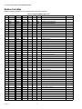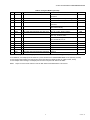
1
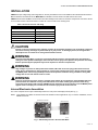
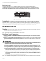
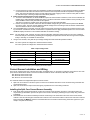
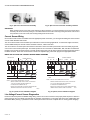
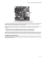
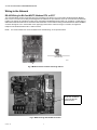
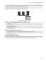
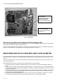
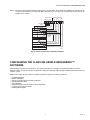
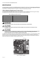
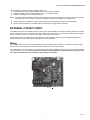
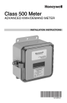
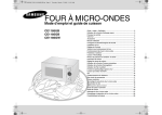
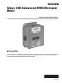
Class 500 Advanced KWh/Demand
Meter
INSTALLATION INSTRUCTIONS
APPLICATION
The Class 500 Meter is a 3-element meter with communications. The device is used to monitor electric power usage of individual
loads after the utility meter. Installation must only be performed by qualified personnel and in accordance with these
instructions and all applicable local and national electrical codes.
62-0304-05
CLASS 500 ADVANCED KWH/DEMAND METER
SPECIFICATIONS
Input Voltage Configuration:
3-wire (Delta) or 4-wire (WYE)
Outdoor Housing Rating (Model numbers with an R at the
end):
NEMA 4
Mains Voltage Input:
Up to 600 VAC RMS available
Indoor Housing Rating (Model numbers without an R at
the end):
NEMA 12
Input Power:
6 VA maximum rating
Display Readout:
KWh accumulated
Current Sensor Rating:
Up to 3200 Amp RMS AC available
Standard Ranges:
(3 or 4 Wire) 120/208-240V: 100,200,400,800,1600, 3200
Amp
(3 or 4 Wire) 277/480V: 100,200,400,800,1600, 3200 Amp
(4 Wire) 346/600 V: 100,200,400,800,1600, 3200 Amp
Power Factor:
.5 leading or lagging
Line Frequency:
50-60 Hz
RS485 Serial Communication Interface:
Cable Specifications: UL listed/rated telephone cord,
4 conductor, 300VAC, stranded conductors, 22-26 AWG.
Input/Output Voltage: Ground isolated +/-5.4 VDC
Cable Connector: RJ-11 connector
Ckt Input Isolation: 5.3 KVAC
Max Cable Distance: 4000 feet
Max Network Nodes: Maximum cabling nodes 52
including master node
Baud Rate: 9600
Metering Accuracy:
Certified to ANSI C12.16
Voltage Operating Range:
+/-10% of rated load
Temperature Range (Class 500):
NEMA 4 (Outdoor) Housing: -20 ºC to +70 ºC
NEMA 12 (Indoor) Housing: -20 ºC to +50 ºC
Communications Options:
RS232/RS485 (Standard) (Requires E-Mon Energy.)
Telephone Modem (Requires E-Mon Energy.)
Ethernet (Requires E-Mon Energy.)
Modbus RTU or TCP/IP (Requires third-party EMS/BMS.)
BACnet IP or MS/TP (Requires third-party EMS/BMS.)
LONworks TP (Twisted Pair) (Requires third-party EMS/
BMS.)
Relative Humidity Range:
0-95% non-condensing
Altitude:
2000 meters maximum
Voltage Overload:
+25% continuously; +100% for 20 cycles
Recommended In-Line Fuse:
Manufacturer: Littelfuse
Mfg Part No.: KLDR.100
Rating:100 mA, time delay. 600 VAC cartridge fuse
Current Sensor Overload:
100% for 1 minute without damaging meter
Pollution Degree:
Degree 2 In accordance with IEC 664
Battery Cell:
Description: Non-rechargeable cell used for memory
retention.
Manufacturer: Eagle-picher
Mfg Part No.: LTC-3PN
Working Voltage: 3.5 Vdc
Current Capacity: 350 mAHr
Electrolyte: Lithium thionyl nitrate
Installation (Overvoltage) Category:
Category III
Measurement Category:
Category III
62-0304—05
2
CLASS 500 ADVANCED KWH/DEMAND METER
INSTALLATION
VERIFY the input voltage rating and configuration on the unit panel label to ensure it is suitable for the intended electrical service.
Meters labeled for 115/208 volt service MUST NOT be installed on service feeds of 277/480 volt and vice versa.
VERIFY that the Class 500 Meter current sensors are sized suitably for the load to be monitored. Compare the color of the arrows
on the current sensors to the chart below to confirm the correct current sensor is being used.
Table 1. Sensor arrow color and rating
Sensor Arrow Color Code
Sensor
Brown
100 Amp
Red
200 Amp
Yellow
400 Amp
Black
800 Amp
Blue
1600 Amp
White/Black
3200 Amp
CAUTION
Internal circuit card components are extremely sensitive to electrostatic discharge. Prior to handling or touching
the internal circuitry, discharge any static build-up on your person. To discharge yourself, touch a grounded
metal object such as conduit or an earth grounded metal enclosure.
WARNING
Use of the Class 500 Meter in a manner inconsistent with this manual or not specified by the manufacturer in
writing can cause permanent damage to the unit and/or serious injury to the operator. The protection and safety
features provided by this equipment may become impaired or otherwise compromised.
WARNING
High voltages are present on main power terminal block, TB1. Risk of serious injury and/or electrical shock
exists. Prior to performing any wiring operations, review all the contents of the user’s manual and de-energize
the MAINS power switch. Only qualified personnel should perform installation wiring. Installation wiring must
comply with all local and national electrical codes.
WARNING
Failure to ground the enclosure creates a possible shock hazard. Do not operate the Class 500 Meter without a
protective earth wire attached securely to the PE terminal screw. After installing the protective earth wiring,
secure the screw tightly (10 N-m torque). NEVER open the front panel of the unit while the unit has MAINS power
applied. Failure to comply can increase the risk of serious injury and for electrical shock.
Internal Electronic Assemblies
The unit is composed of two major subassembly boards: the main power and display boards (See Fig. 1).
NOTE: Units supplied in a NEMA 12 metal enclosure are suitable for indoor applications only. For outdoor installation, use the
NEMA 4 enclosure.
POWER SUPPLY BOARD
DISPLAY BOARD
M28750
Fig. 1. Subassembly boards in the Class 500 Meter.
3
62-0304—05
CLASS 500 ADVANCED KWH/DEMAND METER
Main Power Board
Connections to this board include the MAINS input voltage, current sensors, and external pulse input (See Fig. 2).
The MAINS input terminals are covered with a protective clear shield for safety purposes. The current sensor assemblies
interface to TB2, TB3 or TB4. Each header connector input corresponds to an input voltage phase; therefore, care must be
exercised to ensure each current sensor is connected to the correct input header.
MAINS INPUT TERMINALS
TB2, TB3 AND TB4 SENSOR INTERFACES
M28745
Fig. 2. MAINS power board of the Class 500 Meter.
Display Board
The display board interconnects to the main power board via a flex ribbon cable, and the board mounts on the inside of the
housing door. The only required connection is for RS485 communications. When the meter is operated as a stand-alone unit
using the modem for communications, the RS485 connections are not required. The display board LCD readout indicates the
cumulative kWh value as well as errors associated with the Class 500 Meter, such as low battery or sensor errors.
METER INSTALLATION
Mounting
1.
Using appropriate sized mounting hardware, fasten the Class 500 Meter enclosure to the selected mounting surface. The
four housing mounting holes are centered 6.75” H x 4” W.
NOTE: Units installed outdoors must use the NEMA 4—rated enclosure.
Main Power Board Connections
1.
2.
Installing a temporary ground for ESD protection: With all the circuits de-energized, connect a temporary protective
earth ground connection for ESD protection. Prior to performing any unit wiring, be sure to discharge any static on
your person.
Installing the Class 500 Meter protective earth ground: Connect an earth ground wire to the Class 500 Meter protective
earth ground terminal screw located on the bottom right side of the main power board. After installing the protective earth
ground wire, securely fasten the protective earth ground screw.
WARNING
Failure to attach the protective earth ground wire securely to the enclosure creates a potential shock hazard. Do
not operate the meter without a protective earth ground connection securely installed.
3.
4.
Wire entry: Two openings exist on the standard enclosure; one for 1/2” conduit and one for 3/4” conduit. The 3/4” conduit
opening located on the bottom edge of the housing is used to bring in MAINS power and current sensor wiring. The 1/2”
conduit opening located on the top edge of the housing is used to interface the low voltage signals and RS485 communications wiring to the unit. Route the appropriate cabling to and through the respective enclosure opening.
Unit MAINS wiring:
a. Remove the clear shield located over terminal block TB1 on the main power board. This shield can be removed by
pressing in on each locking tab located at the top of each standoff. While pressing the tabs inward, lift the shield from
the standoffs. Wire each connection to terminal block TB1 with stranded wire 14-12 AWG, rated at 600 VAC.
b. Strip back all wire insulation to expose between 1/4” and 3/8” of the copper conductors. Gently twist each wire’s conductors to prevent fraying. Insert the conductors into their respective terminal block position and tighten down the terminal block screw to securely fasten the conductor. Terminal block TB1 is clearly labeled PHASE A, PHASE B, PHASE C,
and NEUTRAL.
c. Connect the NEUTRAL wire to the appropriate terminal block position.
NOTE: For delta MAINS input wiring, DO NOT connect the NEUTRAL wire. Remove the terminal block screw for this position.
62-0304—05
4
CLASS 500 ADVANCED KWH/DEMAND METER
5.
6.
d. Connect the three AC mains power wires (PHASE A, PHASE B, and PHASE C) to their respective positions as labeled
on terminal block TB1. After all conductors are connected to their respective terminal block positions and tightened
down, verify each terminal block screw is securely fastened by gently tugging on each conductor. Verify that no conductor wires are frayed or shorting to adjacent terminal block positions.
External switch mechanism/in-line fuse installation:
a. To ensure a safe installation, the Class 500 Meter requires an external switch mechanism, such as a circuit breaker, be
installed to the Class 500 Meter MAINS input wiring. The switch mechanism must be installed in close proximity to the
Class 500 Meter and be easily reachable for the operator.
This device must also be marked as the disconnecting device for the Class 500 Meter.
b. Install 1/10 Amp Slow Activation inline fuses with the suitable voltage rating for each conductor phase at the MAINS
input to the meter. The fuses must be labeled to indicate voltage and current rating as well as element characteristics.
The fuse element must be a slow-activating type.
Once the MAINS wiring is complete, close the enclosure front panel and secure the panel to the enclosure using the locking mechanism. Activate the external circuit breaker or equivalent switch to apply AC MAINS power to the unit. The Class
500 Meter display should turn on and indicate total kWh accumulation reading.
NOTE: The unit display, clock, schedule, and other critical configuration parameters will be reset once the unit is completely
wired and ready for commissioning. Resetting and configuring these parameters must be done through a host computer,
locally or remotely, via an RS485 or ethernet link.
7.
Using an AC voltmeter, verify that the input voltage readings are within the limits specified in Table 2.
NOTE: On 3-wire systems the voltages are measured Phase to Phase.
On 4-wire systems the voltages are measured Phase to Neutral.
Table 2. Input voltage limits
Meter Input Voltage/Configuration
Normal Voltage
Limits (+/-10%)
120/208V, 3Ø, 4 Wire
120 VAC
108 to 132 VAC
277/480V, 3Ø, 4 Wire
277 VAC
249 to 305 VAC
8.
346/600V, 3Ø, 4 Wire
346 VAC
311 to 381 VAC
240V, 3Ø, 3 Wire
240 VAC
216 to 264 VAC
480V, 3Ø, 3 Wire
480 VAC
432 to 528 VAC
Remove power from the unit by de-energizing the external switch.
Current Sensor Installation and Wiring
Once the AC voltages have been confirmed to be within acceptable limits, you are ready to install the current sensors. The main
power board contains three header connectors located at the bottom center of the board, TB2, TB3, and TB4.
TB2: Phase A current sensor input
TB3: Phase B current sensor input
TB4: Phase C current sensor input
The Class 500 meters are shipped with split-core current sensors.
1.
2.
Split-core current sensor: This sensor opens so that it can be attached around the circuit conductor being monitored without interrupting power.
Split-core current sensors output a 0-2 VAC signal, proportional to the current being measured.
Installing the Split Core Current Sensor Assembly
1.
2.
Each phase being monitored will require one two-piece current sensor assembly. Therefore, a three-phase meter will
require three (3) assemblies. Open the two-piece current sensor assembly by releasing the nylon clamp using a flat head
screwdriver.
Reassemble the current sensor assembly around the conductor(s) to be monitored. Ensure the current sensor halves
marked “Load” are both facing the load side of the conductor. The colored arrow will be on the source side of the conductor
being monitored and MUST be pointed in a clockwise direction around the conductor being monitored. Tighten the nylon
clamp to complete the assembly.
5
62-0304—05
CLASS 500 ADVANCED KWH/DEMAND METER
Fig. 3. Split core current sensor assembly.
Fig. 4. Split core current sensor assembly installed.
IMPORTANT:
When looking from the source side of the conductor(s) being monitored, you should see the arrow on the current sensor
assembly. The arrow should be pointing in a clockwise direction around the conductor(s) being monitored. If the arrow is
not positioned on the source side, the resulting readings will be inaccurate.
Current Sensor Wiring
Once all the current sensors are installed onto their appropriate phase conductors, you can begin terminating the current sensors
onto the Class 500 Meter main board.
The current sensor leads can be extended up to 500 feet for remote monitoring applications. To extend the length of the wires,
use #22 AWG twisted pair wire with a black and white conductor, rated for 600 VAC.
The current sensor connection points are located on the bottom center of the main power board. Three removable plugs exist,
one for each current sensor phase input. The header portions of the connectors are labeled TB2, TB3, and TB4. The silkscreen
located in front of each connector instructs you which terminal of the plug is for the white conductor and which terminal is wired to
the black conductor. Once each current sensor is wired to its respective plug, insert each plug into the appropriate header.
MAINS LINE VOLTAGE AND CURRENT SENSOR WIRING DIAGRAMS
LINE VOLTAGE
ØA
ØB
ØC
N
B
ØA
LINE VOLTAGE
CURRENT SENSORS
ØB
ØC
W
B
W
B
W
LOAD
SOURCE
ØA
ØB
ØC
N
B
ØA
CURRENT SENSORS
ØB
ØC
B
W
B
W
W
ØA
ØA
ØB
ØB
ØC
ØC
N
LOAD
SOURCE
NOTES: LINE VOLTAGE CONNECTIONS: 14-22 AWG
NOTES: LINE VOLTAGE CONNECTIONS: 14-22 AWG
SENSOR CONNECTIONS: B=BLACK LEAD, W=WHITE LEAD
SENSOR CONNECTIONS: B=BLACK LEAD, W=WHITE LEAD
1/10A, 600 VAC INLINE FUSE PER CONDUCTOR.
LITTLEFUSE PART NUMBER KLDR 100.
1/10A, 600 VAC INLINE FUSE PER CONDUCTOR.
LITTLEFUSE PART NUMBER KLDR 100.
NEUTRAL NOT USED IN DELTA SYSTEM. REMOVE NEUTRAL
TERMINAL BLOCK SCREW FOR DELTA SYSTEMS.
M32788
NEUTRAL NOT USED IN DELTA SYSTEM. REMOVE NEUTRAL
TERMINAL BLOCK SCREW FOR DELTA SYSTEMS.
M32797
Fig. 6. 3-phase, 3-wire installation diagram.
Fig. 5. 3-phase, 4-wire installation diagram.
Line Voltage/Current Sensor Diagnostics
Ensure that the three-phase AC MAINS voltage wiring and the current are connected in the proper phase sequence. If there is a
phase sequence error, the display LCD will show the message “Check Sensor” in the upper right hand corner. Additionally, LED
D5 labeled “MTR” (See Fig. 7) will flash at a rate of twice per second in the event of a phase error or missing phase voltage(s).
62-0304—05
6
CLASS 500 ADVANCED KWH/DEMAND METER
D5
ETHERNET
BOARD
M28748A
Fig. 7. Location of LED D5 (labeled “MTR”) and Ethernet board.
Verify that the AC MAINS voltage wires are all connected to the correct positions on terminal block TB1. Inspect the MAINS input
wiring to verify each conductor is terminated at the correct terminal block position. Using an AC voltmeter, measure the AC
voltage for each Phase to Neutral terminal and to the frame ground point.
Load each current sensor by running at least 1% of the full-scale rated current through the conductor being monitored by each
phase. For example, a 2 Amp load is required on 200 Amp rated sensors for each phase to perform sensor diagnostic
procedures.
• Verify that the current sensor white and black conductors are installed in the correct header positions.
• Verify that the current sensors are installed in the correct direction on the conductor being monitored.
• Verify that the current sensors plugs are terminated in the correct header on the Main Power board.
If the error messages still haven’t been cleared, measure the AC voltage output across the plug terminals of each current sensor
individually. Set the AC voltmeter to the 20 volt scale. If a reading of zero volts is indicated on the voltmeter, check for an open
circuit. An open could exist at the plug terminals or at a splicing junction. Also verify that the core halves are assembled tightly.
Final Main Power Board Checks
Once the phase error has been corrected, the display LCD “Check Sensor” error should extinguish and the main power board
LED D5 should flash at a rate of once per second. Also verify that LED D4, labeled “CPU”, is flashing at a rate of once per second
and synchronously with LED D5.
7
62-0304—05
CLASS 500 ADVANCED KWH/DEMAND METER
Wiring to the Network
RS-485 Wiring for BACnet MS/TP, Modbus RTU, or EZ-7
The Class 500 Meter contains an RS-485 serial communications port allowing it to communicate via BACnet MS/TP, Modbus
RTU, or EZ-7. The units can be daisy-chained together over distances of up to 4000 feet. Up to 52 unit nodes can be networked
together. The meters are networked in a daisy-chain configuration with BELDEN 1120A cable or an equivalent. A cable rating of
600V allows a RS-485 network to be connected to 480-volt meters. Communications wiring should enter/exit the Class 500 Meter
enclosure through the 1/2 in. hole located on the upper (top) surface of the enclosure using a 4-conductor, UL-approved
telephone cord terminated with an RJ-11 male connector.
NOTE: A 3-screw terminal block is also available for the RS-485 wiring, as an optional method.
WIRING METHOD
M28751
TERMINAL LOCATION
Fig. 8. Modbus terminal location and wiring method.
BACNET MS-TP: NOTE
3 POSITION TERMINAL
BLOCK FOR RS-485
CONNECTIONS
Fig. 9. BACnet wiring with RS-485 connection.
62-0304—05
8
CLASS 500 ADVANCED KWH/DEMAND METER
The meter is shipped with a Modbus ID number of 01. This must be changed if the network has more than one meter installed.
The change must be done before the meter is introduced into the network, or it can be put on the network as the only device on
the network and Modbus address changed before adding additional devices.
The meter can be numbered from 1 to 247. There can be no duplicate numbers on a network, so caution must be taken when
assigning a meter ID number prior to its installation on the RS-485 network.
EMS OR CONTROL
UNIT WITH MODBUS
COMMUNICATIONS
M28752
Fig. 10. Modbus installation overview.
METHOD 1: DAISY-CHAIN WITH WIRE TERMINAL (MOST COMMON METHOD)
1. Connect the “HI” terminal (Display PCB J3 Pin 1) of each Class 500 unit together so that all unit Hl terminals are linked (Hl
to Hl to Hl, etc.).
2. Connect the “LO” terminal (Display PCB J3 Pin 2) of each Class 500 unit together so that all unit LO terminals are linked
(LO to LO to LO, etc.).
3. Connect the “GND” terminal (Display PCB J3 Pin 3) of each Class 500 unit together so that all unit GND terminals are
linked (GND to GND to GND, etc.).
4. After completing the wiring of connector J3 for all units, complete the wiring to the EMS through the appropriate input terminals (RS485 or Ethernet).
METHOD 2: DAISY-CHAIN WITH MODULAR JACKS
1. Each display board has two RJ-11 jacks available to facilitate RS-485 daisy-chain connections. Using RJ-11 four-conductor
cable, wire each cable end pin to pin. Interconnect all units together with the RJ-11 cabling.
2. After daisy-chaining the units is complete, the system can be interfaced through the wire terminal on the meter closest to
the EMS (see method 2).
LON and BACnet MS/TP Wiring
For LON and BACnet MS/TP connections, follow standard wiring procedures/topologies for these communication types. Both of
these connections are found on the communications board which sits on the main power board (not on the display board). The
LON is a two position terminal block for twisted pair, and the BACnet MS/TP is a 3 position terminal block.
9
62-0304—05
CLASS 500 ADVANCED KWH/DEMAND METER
SERVICE PIN SWITCH (BLUE
PUSH BUTTON):
BROADCASTS LON NEURON
ID TO LON NETWORK.
ASSISTS IN SETUP OF
DEVICE ON LON NETWORK.
LONWORKS MODULE. NOTE
2 POSITION TERMINAL
BLOCK FOR TWISTED PAIR
CONNECTION
Fig. 11. LON wiring.
Ethernet wiring for BACnet IP, and Modbus TCP/IP and Ethernet EZ-7
These models are shipped with a board that allows for Ethernet communication via Modbus TCP/IP, BACnet IP or Ethernet EZ-7.
EZ-7 protocol is required when using the Energy Software.
Modbus TCP/IP and BACnet IP, and Ethernet EZ-7 connections are made to the RJ45 connection on the Ethernet board (Fig. 7
on page 7). No RS-485 daisy-chain capabilities exist with with these Ethernet connections.
MONITORING MULTIPLE LOADS WITH ONE CLASS 500 METER
The Class 500 Meter provides extreme flexibility by allowing additional sets of current sensors to be used in parallel so multiple
load locations can be monitored by one Class 500 Meter. This feature allows a totalized display readout of two or more load
circuits.
You may use parallel sensors to monitor specific breakers from one panel, specific breakers from more than one panel, two or
more complete panels, etc.
When paralleling current sensors, the following rules must be followed for accurate readings:
1.
2.
3.
4.
Current sensors must be installed in complete sets of three, with a maximum of three sensors installed in parallel per
phase.
All sensors used in parallel must be of the same amperage rating (i.e. 100 Amp, 200 Amp, etc.). The rating is determined
by the current rating (amperage) of the Class 500 Meter. For example, a 200 Amp Class 500 Meter must use extra sets of
200 Amp current sensors.
All locations being monitored must have the same power source. A 480 volt Class 500 Meter, for example, cannot monitor
a 208 volt load circuit nor can a Class 500 Meter monitor two 480 or 208 volt loads if they are from different originating
power sources or from different transformers.
The display readings must be multiplied by the number of sets of current sensors installed. For example, for Class 500
Meter reading of 5 KWH with 2 sets of currents sensors you will have 5 x 2 = 10 KWH (actual usage).
62-0304—05
10
CLASS 500 ADVANCED KWH/DEMAND METER
NOTE: One set of current sensors equates to three sensors, one per phase. The multiplier only applies when extra sets of current sensors are installed on one Class 500 Meter. Therefore, if you are using only one set of three current sensors, the
multiplier is not required.
LINE VOLTAGE
ØA ØB ØC
N
CURRENT SENSORS
ØC
ØA
ØB
B W B W B W
LINE VOLTAGE
LEADS
LOAD A
A
B
C
N
LOAD
SOURCE (LINE)
CURRENT
SENSOR
LEADS
LOAD B
A
B
C
N
CURRENT SENSOR LEADS
LOAD
SOURCE (LINE)
M29307
Fig. 12. Parallel current sensor installation diagrams.
CONFIGURING THE CLASS 500 USING E-MON ENERGY™
SOFTWARE
E-Mon Energy is a product of Honeywell, Inc. This software operates on a computer running Windows 2000, XP, Vista or
Windows 7 and is used to interface to many products including the Class 500. E-Mon Energy Software requires data access via
the EZ-7 protocol.
Reference the E-Mon Energy software for specific instructions to perform the following operations:
•
•
•
•
•
•
•
•
Peak Demand Reset
Modem Initialization
Setting or changing the Remote Dial Out Number
Downloading Profile Data
Unit Initialization
Setting/Changing Unit ID, Group and Location information
Confi guring Unit Call-In schedule
Resetting Meter Display
11
62-0304—05
CLASS 500 ADVANCED KWH/DEMAND METER
MAINTENANCE
The Class 500 Meter unit is shipped in a calibrated and fully functionally tested condition. Since the unit is factory calibrated using
proprietary firmware algorithms, no internal unit adjustments are necessary. This unit contains no internal adjustments. Therefore
no preventative or scheduled maintenance is required, or cleaning or decontamination procedures.
Lithium Battery Replacement Instructions
The Class 500 Meter has a lithium battery cell that is used to retain the contents of SRAM and the RTC during power outages.
The battery has a life expectancy greater than 8 years (See Table 3 for battery specifications).
Table 3. Battery specifications (25 ºC)
Nominal working voltage
3.5 VDC output
Nominal current capacity:
350 mAHr
Cell chemical:
Lithium-thionyl chloride
Operating temperature range:
-40 to +95 ºC
Manufacturer:
Eagle-Picher
Manufacturer’s part number:
LTC-3PN
WARNING
Only replace battery with the exact part number from the manufacturer specified above.
CAUTION
The battery is not completely discharged, therefore DO NOT short the terminals on the battery with any
conductive material.
CAUTION
The internal circuit card components are extremely sensitive to electrostatic discharge. Be careful not to touch
internal circuitry prior to discharging any static build-up on your person. To discharge yourself, touch a
grounded metal object such as a conduit or a metal enclosure exterior.
The battery cell is mounted in a socket on the upper right side of the main power board (See Fig. 13). Should the battery capacity
drop below 2.4 VDC, the display will illuminate a battery symbol on the left margin indicating a low battery. Additionally, the
internal unit firmware will set a flag indicating the low battery condition. When the unit data is next downloaded, the monitoring
facility will be alerted of the low battery and will schedule a service call.
BATTERY
M28744
Fig. 13. Location of battery.
62-0304—05
12
CLASS 500 ADVANCED KWH/DEMAND METER
Use the following procedure to replace the lithium battery cell.
1. Disconnect power from the Class 500 Meter at the unit external circuit breaker.
2. Remove the battery from its socket and place it on a non-conductive surface.
3. Install the new battery into the PCB battery socket.
NOTE: The main power board battery socket is keyed to prevent the user from inserting the new battery in the wrong polarity.
No damage will occur to the unit or battery if the battery is inadvertently installed in the wrong direction.
4.
5.
Visually inspect the new battery to verify that all leads are fully inserted into their respective socket positions.
Dispose of the used battery in accordance with the manufacturer’s (Eagle Picher) instructions.
EXTERNAL CONTACT INPUT
Two additional channels are available (channels 3 and 4) on the Class 500 Meter to be used for capturing pulses from external
devices. These devices can be another electric meter, a water meter, a gas meter, or any unit with an output pulse. The output
pulse of the device must be in the form of a dry contact - either physical or electronic.
Count speeds of up to 10 Hz (600 ppm) are accepted by the Class 500 Meter, and the count is available at Modbus point
locations 41083 and 41085. See the point-map (Table 4) for more information.
Wiring
The external pulse is wired into the Class 500 Meter through the terminals marked “INPUT 1” and “INPUT 2” (TB6 and TB7).
These consist of removable plug and header assemblies similar to the current sensor inputs.
The external device can be mounted up to 100 feet away from the Class 500 Meter, and wire sizes from 24 to 16 gauge (AWG)
can be used for the connection. If the external device utilizes a polarity-dependent, solid-state contact, the plus (+) from
the contact must terminate on the left hand pin of the headers on the Meter.
INPUT 1 and
INPUT 2
13
M29701
62-0304—05
CLASS 500 ADVANCED KWH/DEMAND METER
Modbus Point Map
Modbus data points available from the Class 500 meter. Listed under Class 500.
Table 4. Honeywell Modbus point map
INTEGER W FLOAT
UOM
CALC.
MEM
OP
DESCRIPTION
CLASS 500
1
40001
2 41001
kWh
T-del
NV
R/W
Energy delivered
Y
2
40003
2 41003
kWh
T-rec
NV
R/W
Energy received
Y
3
40005
2 41005
kVARh
T-del
NV
R/W
Reactive energy delivered
Y
4
40007
2 41007
kVARh
T-rec
NV
R/W
Reactive energy received
Y
5
41009
kW
T
R
Real power
Y
6
41011
kVAR
T
R
Reactive power
Y
7
41013
kVA
T
R
Apparent power
Y
8
41015
%
T
R
Power factor
Y
9
41017
Amps
T
R
Current total
Y
10
41019
Amps
A
R
Current average
Y
11
41021
Volts-N
A
R
Voltage line-neutral
Y
12
41023
Volts-L
A
R
Voltage line-line
Y
13
41025
Hz
A
R
Frequency
Y
14
41027
Degree A
R
Phase angle
Y
15
41029
kW
ØA
R
Real power, phase A
Y
16
41031
kW
ØB
R
Real power, phase B
Y
17
41033
kW
ØC
R
Real power, phase C
Y
18
41035
kVAR
ØA
R
Reactive power, phase A
Y
19
41037
kVAR
ØB
R
Reactive power, phase B
Y
20
41039
kVAR
ØC
R
Reactive power, phase C
Y
21
41041
kVA
ØA
R
Apparent power, phase A
Y
22
41043
kVA
ØB
R
Apparent power, phase B
Y
23
41045
kVA
ØC
R
Apparent power, phase C
Y
24
41047
% PF
ØA
R
Power factor, phase A
Y
25
41049
% PF
ØB
R
Power factor, phase B
Y
26
41051
% PF
ØC
R
Power factor, phase C
Y
27
41053
Amps
ØA
R
Current, phase A
Y
28
41055
Amps
ØB
R
Current, phase B
Y
29
41057
Amps
ØC
R
Current, phase C
Y
30
41059
Volts-N
ØA
R
Voltage, line to neutral, phase A-N
Y
31
41061
Volts-N
ØB
R
Voltage, line to neutral, phase B-N
Y
32
41063
Volts-N
ØC
R
Voltage, line to neutral, phase C-N
Y
33
41065
Volts-L
ØA
R
Voltage, line to line, phase A-B
Y
34
41067
Volts-L
ØB
R
Voltage, line to line, phase B-C
Y
35
41069
Volts-L
ØC
R
Voltage, line to line, phase C-A
Y
36
41071
Degree ØA
R
Phase angle, phase A
Y
37
41073
Degree ØB
R
Phase angle, phase B
Y
38
41075
Degree ØC
R
Phase angle, phase C
Y
39
41077
40
41079
41
41081
42
41083
Pulse
Auxiliary Input 1
Y
43
41085
Pulse
Auxiliary Input 2
Y
62-0304—05
14
CLASS 500 ADVANCED KWH/DEMAND METER
Table 4. Honeywell Modbus point map
ITEM
PM-I
W
DATA (SAMPLE)
DESCRIPTION
46001
8 504D 324B 0106 0421 0800 454D 4F4E 2020 Firmware version: PM 5K, Ver, Ver date/time,
Honeywell
46009
8 456E 6572 6779 204D 6574 6572 0000 0000
Device description: Honeywell Energy Meter
R
R
46017
8 1356 4503 0613 0300 0000 0000 0000 0000
Initialize device with date/time
46025
8 1356 4503 0613 0300 0000 0000 0000 0000
RTC date/time, will accept broadcast
command
R/W
W
46033
8 1356 4503 0527 0300 0000 0000 0000 0000
CPU date/time (7 bytes, rest is reserved for
other future formats)
R/W
46041
8 0001 0001 0000 0000 0000 0311 0020 1100
Group, location, Device ID number
R/W
46049
8 0041 0000 0000 0000 0000 0311 0020 1100
Dev. ID, Hookup, Serial numbers….
R/W
46057
8 0592 0007 0000 0000 0000 0000 0000 0000
Recorder info.: idr, dem. int., dem. win.,
dem. syn., timezone, DST…
R/W
46065
8 0101 0001 0D03 3531 1000 0320 0000 0000
Meter info.: SN1&2, pulse rate, Volt/Amp/
CTs, PF/mult1&2, CT, PT
R/W
46513
8 0000 0101 0000 0000 0000 0100 0000 0000
Flags L1
46521
8 0000 0000 0000 0000 0000 0000 0613 0316
Flags L2
46529
8 0000 0000 0000 0000 0000 0000 0000 0000
Flags L3
46537
8 0000 0000 0000 0000 0000 0000 0000 0000
Flags L4
NOTE: To change device ID, set single point at 46049 with data set to new device ID (e.g., 1 to 247).
To set date/time, set multiple points at 46025 for 4 points with data set to HHMM SSDW MMDD YYYY (DW=day of week).
To clear single meter kWh/kW, set single point at 41001 with data set to 0000 (similarly for 41003, 41005, 41007).
To clear multiple meter readings, set multiple point at 41001 for 8 points with data set to 0000's.
NOTE: Jumper J5 & J6 must be closed in order for kWh del/rec and kVARh del/rec to be cleared.
15
62-0304—05
CLASS 500 ADVANCED KWH/DEMAND METER
FREQUENTLY ASKED QUESTIONS
Q. When providing line voltage to the Class 500 Meter, can l tap off of the same breaker l am monitoring?
A. Yes, the voltage can be pulled from the same breaker being monitored.
Q. Can the Class 500 Meter line voltage wires be run in the same conduit as the sensor leads?
A. Yes, there will be no effect on the Class 500 Meter if the sensor leads and line voltage wires are run in the same conduit.
Q. How do l find the cost for kWh and kW to bill my tenants?
A. Your local utility bill should list the cost per kWh and kW. If not, simply call your utility and ask them to provide you with the
cost per kWh and kW.
Q. What size wire do l use for the line voltage leads?
A. These wires are normally sized at #14 AWG, but be sure to confirm this requirement with your local and national electrical
codes requirements.
Q. What size wire should l use to extend the current sensor leads?
A. These wires are normally #14 AWG, twisted pair arrangement. Consult your local electrical code for proper sizing
requirements.
Q. The load l need to monitor has parallel feeds. How do l install the current sensors for this application?
A. There are two ways you can monitor parallel feeds. One method is to clamp the sensors around all feed wires for each
phase. The second way to monitor parallel feeds is to clamp the sensor around one of the feed wires for each phase. When
you read the Class 500, the final reading must be multiplied by the number of feed wires for each phase.
Q. I have two subpanels l would like to monitor with one Class 500 Meter. These subpanels are fed by different
transformers in the building. Can l parallel the sensors and monitor both panels with one Class 500 Meter?
A. No. These panels cannot be monitored by one Class 500 because they are different power sources. When you parallel
current sensors, all loads being monitored must be from the same voltage source.
Automation and Control Solutions
Honeywell International Inc.
1985 Douglas Drive North
Golden Valley, MN 55422
customer.honeywell.com
® U.S. Registered Trademark
© 2011 Honeywell International Inc.
62-0304—05 M.S. Rev. 06-11
Printed in U.S.A.