1
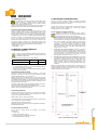
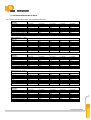
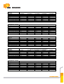
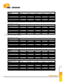
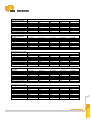
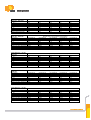
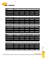
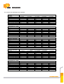
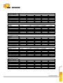
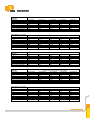
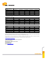
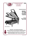
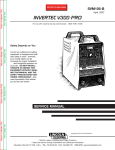
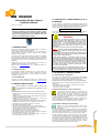
Photovoltaic Module Safety &
Installation Manual
Version: 1.19 - English
NOTICE! Please carefully read and understand the
provided installation manual before installing, wiring,
or operating our product in your PV system. Failure to
follow all proceeding terms and conditions will void
Upsolar’s Limited Warranty contract.
3.0 ELECTRICAL CHARACTERISTICS OF A
PV MODULE
It is very important to understand that a photovoltaic module can have
electrical characteristics different than the (Standard Test Conditions) STC
rating on the module nameplate. Atmospheric conditions often increase the
module’s current and/or voltage higher than that reported at STC.
STC = 1000 W/m2 AM 1.5 25°C
Always refer to your local jurisdictional codes when sizing conductors,
fuses, inverters, and other Balance of System (BOS) components.
WARNING!
1.0 INTRODUCTION
Thank you for choosing the Upsolar Photovoltaic module. Our goal is to
provide you with a top quality long lasting product.
This installation guide, provided by Upsolar Co., Ltd. and supplied with
Upsolar modules, contains information regarding proper handling,
installation, and maintenance.
All instruction in this guide should be read and understood by all parties
before attempting to install Upsolar photovoltaic modules. PV designers
and installers should always comply with all safety precautions listed within
this guide as well as any local or jurisdictional codes that pertain to PV
installations.
Upsolar reserves the right to make changes to both products and
installation manual without prior notice to the customer.
Please contact [email protected] for any additional questions or
explanations.
1.1 Liability Condition
All installation and mounting instructions must be read and
properly understood before attempting to install, wire, and/or
operate PV modules. PV modules generate DC electricity when
exposed to light. This can pose danger to the installer, user,
and/or property. Any contact with electrically active moduleterminals can result in arcing; leading to shocks, burns, fires,
and/or death.
PV modules are electrically live when mounted and installed.
Danger: Electrical potential (SHOCK DANGER) increases with
parallel (higher currents) and series (higher voltage) connection
of PV modules.
The PV installer must assume all inherent risk of property damage
and/or personal injury related to the mishandling of PV modules
during installation and maintenance.
"Under normal conditions, a photovoltaic module is likely to
experience conditions that produce more current and/or voltage
than reported at standard test conditions. Accordingly, the values
of ISC and VOC marked on this module should be multiplied by a
factor of 1.25 when determining component voltage ratings,
conductor current ratings, fuse sizes, and size of controls
connected to the PV output." (Extract from IEC 61730-1 clause
12.7 and UL1703 clause 48.9)
“Refer to Section 690-8 of the National Electrical Code for an
additional multiplying factor of 125 percent (80 percent derating)
which may be applicable.” (according to UL1703, clause 48.6)
The installation techniques, handling and use of Upsolar product are
beyond Upsolar’s company control. Therefore, Upsolar does not assume
responsibility for loss, damage or expense resulting from improper
installation, handling or use.
4.0 ELECTRICAL CONFIGURATIONS
1.2 Limited Warranty
Please follow all module specification and jurisdictional laws regarding
interconnection of PV modules. Photovoltaic modules can be connected in
both series and/or parallel to attain the desired electrical output.
Combined source circuits should contain only 1 type of PV module.
All Upsolar PV module warranties are listed in the Upsolar warranty
conditions which can be downloaded from our website. www.upsolar.com
2.0 SAFETY PRECAUTIONS
Before installing or operating modules, please read
and understand all general safety instructions in this
manual!
Module Installation should only be carried out by qualified individuals.
• Always follow and observe all appropriate regional and jurisdictional
electric codes.
• Always use properly insulated and/or rated electrical and mechanical
tools during installation of PV modules
• Always mount PV modules over a fire resistant roof, in case of roof
mounting (according to IEC 61730-1 clause 12.4)
• Always ground all PV modules according to the local electrical codes.
• Always use only the same type of PV modules within 1 PV circuit.
• Do not step on or put heavy/sharp objects on PV module.
• Do not disconnect module under load.
• Do not use artificial methods for cooling the PV module (water).
• Do not touch PV module terminals (avoid wearing metallic jewelry or
devices attached to the body during installation).
• Do not install PV modules in wet or windy conditions.
• Do not drill extra holes in module frame or glass surface
• Do not store or install PV modules near flammable gasses or materials
• Do not disassemble any part of the PV module
• Do not expose the artificially concentrated sunlight to a module or
panel (according to IEC 61730-1 clause 12.5)
4.1 General Wiring / Configuration
Conductors must meet or exceed the following requirements (IEC 61730-1
clause 12.3):
- Size: minimum 4.0 mm2 (12 AWG) for modules connected in series
- Temperature rating (-40°C to +90°C)
- Type PV-wire, USE-2 or equivalent
4.2 Maximum Voltage (i.e. series connections)
The maximum PV system voltage for a circuit should be
calculated as the sum of the rated open circuit voltage of the
series connected PV modules (corrected for the lowest
expected ambient temperature). Open Circuit Voltage should
be used to determine the voltage rating of all other BOS (Balance of
System) components in the system
The open voltage of each string must never exceed the maximum system
voltage value defined by the local regulation (IEC 61730-1 clause 12.3)
Refer to the datasheets for PV modules Temperature Coefficients.
4.3 PV Module and Equipment Grounding
Please refer to the applicable regional and local codes in
regards to grounding PV modules, and other PV system
components.
If PV modules individual grounding is requested by the local legislation,
Upsolar PV modules should be grounded to the module frame using one of
the provided grounding holes (Figure 1). Please refer to NEC Article 250,
690.41-690.49, and UL Standard 1703 for proper grounding procedures.
Example (according to IEC61730-1 clause 12.3): Remove any anodization
or oxidation from the module frame at the grounding lug point of contact.
Apply a thin coat of anti-oxidant film, then use a stainless steel M10 screw
(with serrated screwhead to penetrate the frame anodized layer), nut, and
lock washer to attach an outdoor rated tin-plated copper lug. Attach an
equipment grounding conductor (4mm2-12AWG-not provided by Upsolar)
to the installed grounding lug (not provided by Upsolar).
4.4 Lightning protection
6.0 MOUNTING CONFIGURATIONS
PV systems do not generally increase the risk of buildings being
struck by lightning. If a lightning protection system currently
exists on the installation building, the PV system should be
connected to any lightning protection system.
Always try and select a suitable orientation to maximize the sunlight
exposure to the PV module surface. Shading can significantly affect the
module and string performance in a PV array.
Surge arrestors on the DC side of the PV system are recommended. If no
lightning protection exists, all PV modules should be earth-grounded.
4.5 Overcurrent Protection (OCPD))
When the potential reverse current of a PV string exceeds the rated
Upsolar PV module series fuse rating (values indicated in part 8.0 PV
modules electrical data) an overcurrent protection device (OCPD) must be
used (IEC 61730-1 clause 12.3). 1 or 2 strings of PV modules in parallel do
not require OCPD’s, but 3 or more PV strings in parallel will usually require
an OCPD. In this case, it is recommended to use one fuse per string rated
at 1.56 x Isc or higher (Isc is the PV module short circuit current at STC).
Example of fuse types: DCM 600Vdc for UL or PV Fuse – 1000Vdc for IEC.
Sufficient space between the module frames and mounting structure is
required to prevent module damage and to reduce high operating
temperatures due to poor air circulation.
6.1 PV modules mounting techniques
Upsolar PV modules can be mounted either vertical or
landscape as long as one of the following mounting procedures
is followed (according to IEC 61730-1 clause 12.4)
1.
Mounting clamps (for open-rack and roof installations): Attach
the PV module to the mounting system using Clamps or Clips from a
certified manufacture according to their instructions. Clamp and/or
clips should be spaced at ¼ the length or width from the frame ends
(± 5 cm). Top mount clamps/clips should always be mounted
symmetrically. See figure 1. Upsolar recommend the following
minimum dimensions for each clamp: catch length: 30.0mm, catch
width: 5.0mm, thickness: 3.0mm. The torque recommended to fix the
clamps is 15 N.m (11.1 lb.ft).
2.
Frame Holes (for open-rack systems): Attach the PV module to
the mounting system using the provided factory mounting holes. At
least 4 points of connection are required between each module and
the mounting surface. It is recommended that 4 M6 (1/4”) SS bolts
with nuts and washers are used on each module. The torque
recommended to fix the bolts is 15 N.m (11.1 lb.ft).
3.
End Mount (for open-rack and roof installations): End mounting
is the capture mounting of the length of the module’s end frame to a
supporting rail. The end frames are on the shorter sides of the
module. The end-mounting rail and clips or clamps must be of
sufficient strength to allow for maximum design pressure of the
module. Verify this capacity with the mounting system vendor before
installation.
Each Upsolar module is equipped with 3 by-pass diodes (Schottky type)
connected in parallel of the strings of cells to limit the cells heating in case
of shading (hot-spot effect). The characteristics of these diodes are:
- Voltage rating: VRRM = 45 V
- Current rating: IF = 15 A
5.0 MODULE CHARACTERISTICS
5.1 Operating Temperature
Always try to provide adequate ventilation around installed PV
modules, especially in hot environments. Cells performance will
be affected by temperature.
Predetermined Nominal Temperatures for Upsolar Modules:
Maximum Operating Temperature
+90° C
+194° F
Minimum Operating Temperature
-40° C
-40° F
Table 1: UPSOLAR MODULE OPERATING TEMPERATURES
• It is recommended that at least 5 cm or 2 inches is maintained between
the mounting surface and the PV module.
• ≥ (3/16) inch or 5 mm gap is recommended between adjoining modules
to allow for thermal expansion.
Slope: PV module has class C fire rating and must be installed over a roof
with appropriate fire resistance. A minimum slope of 5”/ft for installation is
required to maintain fire class rating. Further consult local, regional and
national building fire statutory regulation.
5.2 PV Module Design Strength
Upsolar PV modules have been tested according to IEC design
qualification type EN 61215: 2005 and IEC safety standard EN 617301&2:2007 (Application class A, refer to clause 12.1).
Modules rated for use in the application class A may be used in systems
operating at greater than 50 V DC or 240 W, where general contact access
is anticipated. Modules qualified for safety through this part of IEC 61730
and IEC 61730-2 and within this application class are considered to meet
the requirements for safety class II.
Upsolar PV modules have passed the mechanical load test to 5400 Pa.
This corresponds to a wind speed of approximately 250 mph.
Upsolar PV modules comply with the test requirements for UL 790 Class C
Spread of Flame Test and Burning Brand Test.
5.3 Mounting Hardware
All hardware that comes into contact with the PV module frame should be
corrosion and UV resistant. Damage to the module frame or structure
could occur if improper materials are used.
Stainless Steel = M6 (1/4”) Nuts, Bolts, Washers
To minimize galvanic corrosion similar metals to aluminum should be used
when in contact with the PV module frame.
Upsolar Module Frame material: Aluminum
Always apply proper torque settings to all mounting hardware according to
manufactures specifications.
5.4 Operating Environments
Do not mount or operate Upsolar PV modules in the following
environments:
• Extreme wind
• Extreme temperature (see Table 1)
• Corrosive, salty, acidic, or sulfurous environments
• Near flammable gasses or materials
Figure 1: Module Mounting Location
Figure 2: Module installation diagram (recommended)
6.2 PV modules handling
1.
Do not expose to the PV module to excessive load on the surface
or bend the frame. DANGER: Risk of breaking Glass!
2.
Do not stand or step on the PV module.. The glass may be slippery.
DANGER: Risk
isk of injury and electric shock if glass is broken!
broken
3.
PV modules are heavy. Please handle with care! It is recommended
for two qualified personal to handle one PV module
at a time
4.
Do not hit or put excessive load on the glass or back sheet. PV
cells may break.
5.
Do not twist the interconnect cable excessively. NEVER expose
cables, wires, or other electrical parts to water! DANGER: risk of
electric shock!
6.
Do not drill holes in the frame.
ame. Modifications void the PV Module
warranty
7.
Do not touch the PV Module with bare hands. The frame of the PV
Module has sharp edges and may cause injury. Wear suitable
gloves when handling the PV Module.
8.
Do not drop the PV Module or allow objects
ob
to fall on the PV
module.
9.
The packaging is not resistant to weathering. Do store PV modules
in a dry place and NEVER expose directly to water (eg. Rain).
10.
Transport the PV Modules to the installation site in the original
packaging.
11.
Protect the module cables from
rom mechanical stress during transport
and handling. ATTENTION: Never pull on cables!
12.
Handle modules with care when lifting them from pallets. Never
stack pallets and stack a maximum of 23 modules per pallet only –
use appropriate Upsolar plastic corners when stacking PV Modules.
13.
Check the PV modules for damage after unpacking.
14.
Do not install damaged PV Modules. When in doubt about the
condition of a PV module, please contact Upsolar
Upsol customer service
for advice.
15.
Always wear protective head gear, insulating gloves and safety
shoes (with rubber soles) when installing PV modules
7.0 MAINTENANCE
Annual inspection of the PV modules, array, and BOS is highly
recommended. The following items (regarding the PV modules) should
be checked periodically to keep the PV system functioning correctly for
many years.
1.
Ensure there is no corrosion on any mechanical connection between
the PV module and the mounting structure. Tighten all loose
components to specified torque settings.
2.
Check all electrical connection for corrosion and separation on PV
modules (connectors, cables, and grounds). Never disconnect PV
modules under load!
3.
Make sure PV modules are clean and free of dirt and dust.
dust Use
water and a soft sponge or cloth for cleaning. A mild, non-abrasive
non
cleaning agent can be used if necessary.
•
•
•
•
4.
Critical Cleaning Liquid Detergent is recommended. Do not use
dishwasher detergent!
Use water pressure of 45 PSI (3 bar) or less.
De-ionized
ionized water is recommended if available.
Do not use cold water on hot modules
Make sure all maintenance work is executed by qualified personnel
only.
8.0 PV MODULES ELECTRICAL DATA:
PV modules with standard frames and standard junction box:
Monocrystalline 5” – 72 cells
White type
Module type
Pm (Wp)
Vm (V)
Im (A)
Voc (V)
Isc (A)
Maximum System voltage (IEC)
Maximum System voltage (UL)
Maximum Reverse Current
UP-M185M
185
36.0
5.14
44.8
5.43
1000V
600V
15A
UP-M190M
190
36.3
5.23
45.1
5.55
1000V
600V
15A
Monocrystalline 5” – 72 cells
Black type
Module type
Pm (Wp)
Vm (V)
Im (A)
Voc (V)
Isc (A)
Maximum System voltage (IEC)
Maximum System voltage (UL)
Maximum Reverse Current
UP-M185M-B
185
36.4
5.08
45.0
5.30
1000V
600V
15A
UP-M190M-B
190
36.6
5.19
45.3
5.40
1000V
600V
15A
Monocrystalline 6” – 60 cells
White type
Module type
Pm (Wp)
Vm (V)
Im (A)
Voc (V)
Isc (A)
Maximum System voltage (IEC)
Maximum System voltage (UL)
Maximum Reverse Current
UP-M240M
240
29.6
8.10
37.1
8.60
1000V
600V
20A
UP-M245M
245
29.8
8.22
37.4
8.70
1000V
600V
20A
Monocrystalline 6” – 60 cells
Black type
Module type
Pm (Wp)
Vm (V)
Im (A)
Voc (V)
Isc (A)
Maximum System voltage (IEC)
Maximum System voltage (UL)
Maximum Reverse Current
UP-M235M-B
235
29.8
7.88
37.1
8.40
1000V
600V
20A
UP-M240M-B
240
30.0
8.00
37.4
8.50
1000V
600V
20A
Monocrystalline 6” – 72 cells
White type
Module type
Pm (Wp)
Vm (V)
Im (A)
Voc (V)
Isc (A)
Maximum System voltage (IEC)
Maximum System voltage (UL)
Maximum Reverse Current
UP-M290M
290
35.6
8.15
44.6
8.64
1000V
600V
20A
UP-M295M
295
35.8
8.24
44.9
8.72
1000V
600V
20A
Modules rating at STC (Standard Test Conditions)
UP-M195M
195
36.6
5.33
45.4
5.65
1000V
600V
15A
UP-M200M
200
37.0
5.41
46.0
5.70
1000V
600V
15A
UP-M205M
205
37.4
5.48
46.6
5.75
1000V
600V
15A
Modules rating at STC (Standard Test Conditions)
UP-M195M-B
195
36.8
5.30
45.6
5.50
1000V
600V
15A
UP-M200M-B
200
37
5.41
45.9
5.60
1000V
600V
15A
UP-M205M-B
205
37.2
5.51
46.2
5.70
1000V
600V
15A
Modules rating at STC (Standard Test Conditions)
UP-M250M
250
30.0
8.34
37.7
8.80
1000V
600V
20A
UP-M255M
255
30.2
8.44
38.0
8.88
1000V
600V
20A
UP-M260M
260
30.4
8.55
38.3
8.96
1000V
600V
20A
Modules rating at STC (Standard Test Conditions)
UP-M245M-B
245
30.2
8.12
37.7
8.60
1000V
600V
20A
UP-M250M-B
250
30.3
8.24
38.0
8.70
1000V
600V
20A
UP-M255M-B
255
30.5
8.36
38.3
8.80
1000V
600V
20A
Modules rating at STC (Standard Test Conditions)
UP-M300M
300
36.0
8.34
45.2
8.80
1000V
600V
20A
UP-M305M
305
36.2
8.43
45.5
8.88
1000V
600V
20A
UP-M310M
310
36.4
8.52
45.8
8.96
1000V
600V
20A
Monocrystalline 6” – 72 cells
Black type
Module type
Pm (Wp)
Vm (V)
Im (A)
Voc (V)
Isc (A)
Maximum System voltage (IEC)
Maximum System voltage (UL)
Maximum Reverse Current
UP-M290M-B
290
36.0
8.06
45.0
8.54
1000V
600V
20A
UP-M295M-B
295
36.2
8.15
45.3
8.62
1000V
600V
20A
Polycrystalline 6” – 54 cells
White type
Module type
Pm (Wp)
Vm (V)
Im (A)
Voc (V)
Isc (A)
Maximum System voltage (IEC)
Maximum System voltage (UL)
Maximum Reverse Current
UP-M210P
210
26.8
7.84
33.3
8.40
1000V
600V
20A
UP-M215P
215
27.2
7.91
33.4
8.47
1000V
600V
20A
Polycrystalline 6” – 54 cells
Black type
Module type
Pm (Wp)
Vm (V)
Im (A)
Voc (V)
Isc (A)
Maximum System voltage (IEC)
Maximum System voltage (UL)
Maximum Reverse Current
UP-M210P-B
210
27.0
7.79
33.5
8.35
1000V
600V
20A
UP-M215P-B
215
27.4
7.85
33.6
8.42
1000V
600V
20A
Polycrystalline 6” – 60 cells
White type
Module type
Pm (Wp)
Vm (V)
Im (A)
Voc (V)
Isc (A)
Maximum System voltage (IEC)
Maximum System voltage (UL)
Maximum Reverse Current
UP-M230P
230
29.7
7.75
37.2
8.30
1000V
600V
20A
UP-M235P
235
30.0
7.84
37.4
8.35
1000V
600V
20A
Polycrystalline 6” – 60 cells
Black type
Module type
Pm (Wp)
Vm (V)
Im (A)
Voc (V)
Isc (A)
Maximum System voltage (IEC)
Maximum System voltage (UL)
Maximum Reverse Current
UP-M230P-B
230
29.9
7.70
37.4
8.25
1000V
600V
20A
UP-M235P-B
235
30.2
7.79
37.6
8.30
1000V
600V
20A
Modules rating at STC (Standard Test Conditions)
UP-M300M-B
300
36.4
8.24
45.6
8.70
1000V
600V
20A
UP-M305M-B
305
36.6
8.33
45.9
8.78
1000V
600V
20A
UP-M310M-B
310
36.8
8.42
46.2
8.86
1000V
600V
20A
Modules rating at STC (Standard Test Conditions)
UP-M220P
220
27.4
8.03
33.5
8.54
1000V
600V
20A
UP-M225P
225
27.6
8.15
33.6
8.61
1000V
600V
20A
UP-M230P
230
27.8
8.27
33.7
8.68
1000V
600V
20A
Modules rating at STC (Standard Test Conditions)
UP-M220P-B
220
27.6
7.97
33.7
8.49
1000V
600V
20A
UP-M225P-B
225
27.8
8.09
33.8
8.56
1000V
600V
20A
UP-M230P-B
230
28.0
8.21
33.9
8.63
1000V
600V
20A
Modules rating at STC (Standard Test Conditions)
UP-M240P
240
30.2
7.95
37.6
8.40
1000V
600V
20A
UP-M245P
245
30.4
8.06
37.8
8.45
1000V
600V
20A
UP-M250P
250
30.6
8.17
38.0
8.50
1000V
600V
20A
Modules rating at STC (Standard Test Conditions)
UP-M240P-B
240
30.4
7.89
37.8
8.35
1000V
600V
20A
UP-M245P-B
245
30.6
8.00
38.0
8.40
1000V
600V
20A
UP-M250P-B
250
30.9
8.10
38.2
8.45
1000V
600V
20A
Polycrystalline 6” – 72 cells
White type
Module type
Pm (Wp)
Vm (V)
Im (A)
Voc (V)
Isc (A)
Maximum System voltage (IEC)
Maximum System voltage (UL)
Maximum Reverse Current
UP-M285P
285
35.4
8.06
45.0
8.42
1000V
600V
20A
UP-M290P
290
35.5
8.17
45.2
8.50
1000V
600V
20A
Polycrystalline 6” – 72 cells
Black type
Module type
Pm (Wp)
Vm (V)
Im (A)
Voc (V)
Isc (A)
Maximum System voltage (IEC)
Maximum System voltage (UL)
Maximum Reverse Current
UP-M285P-B
285
35.6
8.01
45.0
8.39
1000V
600V
20A
UP-M290P-B
290
35.7
8.12
45.1
8.47
1000V
600V
20A
Modules rating at STC (Standard Test Conditions)
UP-M295P
295
35.7
8.26
45.4
8.58
1000V
600V
20A
UP-M300P
300
35.9
8.36
45.6
8.66
1000V
600V
20A
UP-M305P
305
36.1
8.45
45.8
8.74
1000V
600V
20A
Modules rating at STC (Standard Test Conditions)
UP-M295P-B
295
35.9
8.22
45.2
8.55
1000V
600V
20A
UP-M300P-B
300
36.1
8.31
45.3
8.63
1000V
600V
20A
UP-M305P-B
305
36.3
8.40
45.4
8.71
1000V
600V
20A
PV modules with Tigo DC maximizer
Monocrystalline 5” – 72 cells
White type
Module type
Pm (Wp)
Vm (V)
Im (A)
Voc (V)
Isc (A)
Maximum System voltage (IEC)
Maximum System voltage (UL)
Maximum Reverse Current
UP-M185MT
185
36.0
5.14
44.8
5.43
1000V
600V
15A
UP-M190MT
190
36.3
5.23
45.1
5.55
1000V
600V
15A
Monocrystalline 5” – 72 cells
Black type
Module type
Pm (Wp)
Vm (V)
Im (A)
Voc (V)
Isc (A)
Maximum System voltage (IEC)
Maximum System voltage (UL)
Maximum Reverse Current
UP-M185MT-B
185
36.4
5.08
45.0
5.30
1000V
600V
15A
UP-M190MT-B
190
36.6
5.19
45.3
5.40
1000V
600V
15A
Monocrystalline 5” – 72 cells
White type – Solrif frame
Module type
Pm (Wp)
Vm (V)
Im (A)
Voc (V)
Isc (A)
Maximum System voltage (IEC)
Maximum System voltage (UL)
Maximum Reverse Current
Modules rating at STC (Standard Test Conditions)
UP-M195MT
195
36.6
5.33
45.4
5.65
1000V
600V
15A
UP-M200MT
200
37.0
5.41
46.0
5.70
1000V
600V
15A
UP-M205MT
205
37.4
5.48
46.6
5.75
1000V
600V
15A
Modules rating at STC (Standard Test Conditions)
UP-M195MT-B
195
36.8
5.30
45.6
5.50
1000V
600V
15A
UP-M200MT-B
200
37
5.41
45.9
5.60
1000V
600V
15A
UP-M205MT-B
205
37.2
5.51
46.2
5.70
1000V
600V
15A
Modules rating at STC (Standard Test Conditions)
UP-S185MT
185
36.0
5.14
44.8
5.43
1000V
600V
15A
UP-S190MT
190
36.3
5.23
45.1
5.55
1000V
600V
15A
UP-S195MT
195
36.6
5.33
45.4
5.65
1000V
600V
15A
UP-S200MT
200
37.0
5.41
46.0
5.70
1000V
600V
15A
UP-S205MT
205
37.4
5.48
46.6
5.75
1000V
600V
15A
Monocrystalline 5” – 72 cells
Black type – Solrif frame
Module type
Pm (Wp)
Vm (V)
Im (A)
Voc (V)
Isc (A)
Maximum System voltage (IEC)
Maximum System voltage (UL)
Maximum Reverse Current
UP-S185MT-B
185
36.4
5.08
45.0
5.30
1000V
600V
15A
UP-S190MT-B
190
36.6
5.19
45.3
5.40
1000V
600V
15A
Monocrystalline 5” – 72 cells
White type – ZEP frame
Module type
Pm (Wp)
Vm (V)
Im (A)
Voc (V)
Isc (A)
Maximum System voltage (IEC)
Maximum System voltage (UL)
Maximum Reverse Current
UP-Z185MT
185
36.0
5.14
44.8
5.43
1000V
600V
15A
UP-Z190MT
190
36.3
5.23
45.1
5.55
1000V
600V
15A
Monocrystalline 5” – 72 cells
Black type – ZEP frame
Module type
Pm (Wp)
Vm (V)
Im (A)
Voc (V)
Isc (A)
Maximum System voltage (IEC)
Maximum System voltage (UL)
Maximum Reverse Current
UP-Z185MT-B
185
36.4
5.08
45.0
5.30
1000V
600V
15A
UP-Z190MT-B
190
36.6
5.19
45.3
5.40
1000V
600V
15A
Monocrystalline 6” – 60 cells
White type
Module type
Pm (Wp)
Vm (V)
Im (A)
Voc (V)
Isc (A)
Maximum System voltage (IEC)
Maximum System voltage (UL)
Maximum Reverse Current
UP-M240MT
240
29.6
8.10
37.1
8.60
1000V
600V
15A
UP-M245MT
245
29.8
8.22
37.4
8.70
1000V
600V
15A
Monocrystalline 6” – 60 cells
Black type
Module type
Pm (Wp)
Vm (V)
Im (A)
Voc (V)
Isc (A)
Maximum System voltage (IEC)
Maximum System voltage (UL)
Maximum Reverse Current
UP-M235MT-B
235
29.8
7.88
37.1
8.40
1000V
600V
15A
UP-M240MT-B
240
30.0
8.00
37.4
8.50
1000V
600V
15A
Modules rating at STC (Standard Test Conditions)
UP-S195MT-B
195
36.8
5.30
45.6
5.50
1000V
600V
15A
UP-S200MT-B
200
37
5.41
45.9
5.60
1000V
600V
15A
UP-S205MT-B
205
37.2
5.51
46.2
5.70
1000V
600V
15A
Modules rating at STC (Standard Test Conditions)
UP-Z195MT
195
36.6
5.33
45.4
5.65
1000V
600V
15A
UP-Z200MT
200
37.0
5.41
46.0
5.70
1000V
600V
15A
UP-Z205MT
205
37.4
5.48
46.6
5.75
1000V
600V
15A
Modules rating at STC (Standard Test Conditions)
UP-Z195MT-B
195
36.8
5.30
45.6
5.50
1000V
600V
15A
UP-Z200MT-B
200
37
5.41
45.9
5.60
1000V
600V
15A
UP-Z205MT-B
205
37.2
5.51
46.2
5.70
1000V
600V
15A
Modules rating at STC (Standard Test Conditions)
UP-M250MT
250
30.0
8.34
37.7
8.80
1000V
600V
15A
UP-M255MT
255
30.2
8.44
38.0
8.88
1000V
600V
15A
UP-M260MT
260
30.4
8.55
38.3
8.96
1000V
600V
15A
Modules rating at STC (Standard Test Conditions)
UP-M245MT-B
245
30.2
8.12
37.7
8.60
1000V
600V
15A
UP-M250MT-B
250
30.3
8.24
38.0
8.70
1000V
600V
15A
UP-M255MT-B
255
30.5
8.36
38.3
8.80
1000V
600V
15A
Monocrystalline 6” – 60 cells
White type – ZEP frame
Module type
Pm (Wp)
Vm (V)
Im (A)
Voc (V)
Isc (A)
Maximum System voltage (IEC)
Maximum System voltage (UL)
Maximum Reverse Current
Modules rating at STC (Standard Test Conditions)
UP-Z240MT
240
29.6
8.10
37.1
8.60
1000V
600V
15A
UP-Z245MT
245
29.8
8.22
37.4
8.70
1000V
600V
15A
Monocrystalline 6” – 60 cells
Black type – ZEP frame
Module type
Pm (Wp)
Vm (V)
Im (A)
Voc (V)
Isc (A)
Maximum System voltage (IEC)
Maximum System voltage (UL)
Maximum Reverse Current
UP-Z235MT-B
235
29.8
7.88
37.1
8.40
1000V
600V
15A
UP-Z240MT-B
240
30.0
8.00
37.4
8.50
1000V
600V
15A
Polycrystalline 6” – 54 cells
White type
Module type
Pm (Wp)
Vm (V)
Im (A)
Voc (V)
Isc (A)
Maximum System voltage (IEC)
Maximum System voltage (UL)
Maximum Reverse Current
UP-M210PT
210
26.8
7.84
33.3
8.40
1000V
600V
15A
UP-M215PT
215
27.2
7.91
33.4
8.47
1000V
600V
15A
UP-Z250MT
250
30.0
8.34
37.7
8.80
1000V
600V
15A
UP-Z255MT
255
30.2
8.44
38.0
8.88
1000V
600V
15A
UP-Z260MT
260
30.4
8.55
38.3
8.96
1000V
600V
15A
Modules rating at STC (Standard Test Conditions)
UP-Z245MT-B
245
30.2
8.12
37.7
8.60
1000V
600V
15A
UP-Z250MT-B
250
30.3
8.24
38.0
8.70
1000V
600V
15A
UP-Z255MT-B
255
30.5
8.36
38.3
8.80
1000V
600V
15A
Modules rating at STC (Standard Test Conditions)
Polycrystalline 6” – 54 cells
Black type
Module type
Pm (Wp)
Vm (V)
Im (A)
Voc (V)
Isc (A)
Maximum System voltage (IEC)
Maximum System voltage (UL)
Maximum Reverse Current
UP-M210PT-B
210
27.0
7.79
33.5
8.35
1000V
600V
15A
UP-M215PT-B
215
27.4
7.85
33.6
8.42
1000V
600V
15A
Polycrystalline 6” – 60 cells
White type
Module type
Pm (Wp)
Vm (V)
Im (A)
Voc (V)
Isc (A)
Maximum System voltage (IEC)
Maximum System voltage (UL)
Maximum Reverse Current
UP-M230PT
230
29.7
7.75
37.2
8.30
1000V
600V
15A
UP-M235PT
235
30.0
7.84
37.4
8.35
1000V
600V
15A
UP-M220PT
220
27.4
8.03
33.5
8.54
1000V
600V
15A
UP-M225PT
225
27.6
8.15
33.6
8.61
1000V
600V
15A
UP-M230PT
230
27.8
8.27
33.7
8.68
1000V
600V
15A
Modules rating at STC (Standard Test Conditions)
UP-M220PT-B
220
27.6
7.97
33.7
8.49
1000V
600V
15A
UP-M225PT-B
225
27.8
8.09
33.8
8.56
1000V
600V
15A
UP-M230PT-B
230
28.0
8.21
33.9
8.63
1000V
600V
15A
Modules rating at STC (Standard Test Conditions)
UP-M240PT
240
30.2
7.95
37.6
8.40
1000V
600V
15A
UP-M245PT
245
30.4
8.06
37.8
8.45
1000V
600V
15A
UP-M250PT
250
30.6
8.17
38.0
8.50
1000V
600V
15A
Polycrystalline 6” – 60 cells
Black type
Module type
Pm (Wp)
Vm (V)
Im (A)
Voc (V)
Isc (A)
Maximum System voltage (IEC)
Maximum System voltage (UL)
Maximum Reverse Current
UP-M230PT-B
230
29.9
7.70
37.4
8.25
1000V
600V
15A
UP-M235PT-B
235
30.2
7.79
37.6
8.30
1000V
600V
15A
Polycrystalline 6” – 60 cells
White type – ZEP frame
Module type
Pm (Wp)
Vm (V)
Im (A)
Voc (V)
Isc (A)
Maximum System voltage (IEC)
Maximum System voltage (UL)
Maximum Reverse Current
UP-Z230PT
230
29.7
7.75
37.2
8.30
1000V
600V
15A
UP-Z235PT
235
30.0
7.84
37.4
8.35
1000V
600V
15A
Polycrystalline 6” – 60 cells
Black type – ZEP frame
Module type
Pm (Wp)
Vm (V)
Im (A)
Voc (V)
Isc (A)
Maximum System voltage (IEC)
Maximum System voltage (UL)
Maximum Reverse Current
UP-Z230PT-B
230
29.9
7.70
37.4
8.25
1000V
600V
15A
UP-Z235PT-B
235
30.2
7.79
37.6
8.30
1000V
600V
15A
Polycrystalline 6” – 72 cells
White type
Module type
Pm (Wp)
Vm (V)
Im (A)
Voc (V)
Isc (A)
Maximum System voltage (IEC)
Maximum System voltage (UL)
Maximum Reverse Current
UP-M285PT
285
35.4
8.06
45.0
8.42
1000V
600V
15A
UP-M290PT
290
35.5
8.17
45.2
8.50
1000V
600V
15A
Polycrystalline 6” – 72 cells
Black type
Module type
Pm (Wp)
Vm (V)
Im (A)
Voc (V)
Isc (A)
Maximum System voltage (IEC)
Maximum System voltage (UL)
Maximum Reverse Current
UP-M285PT-B
285
35.6
8.01
45.0
8.39
1000V
600V
15A
UP-M290PT-B
290
35.7
8.12
45.1
8.47
1000V
600V
15A
Modules rating at STC (Standard Test Conditions)
UP-M240PT-B
240
30.4
7.89
37.8
8.35
1000V
600V
15A
UP-M245PT-B
245
30.6
8.00
38.0
8.40
1000V
600V
15A
UP-M250PT-B
250
30.9
8.10
38.2
8.45
1000V
600V
15A
Modules rating at STC (Standard Test Conditions)
UP-Z240PT
240
30.2
7.95
37.6
8.40
1000V
600V
15A
UP-Z245PT
245
30.4
8.06
37.8
8.45
1000V
600V
15A
UP-Z250PT
250
30.6
8.17
38.0
8.50
1000V
600V
15A
Modules rating at STC (Standard Test Conditions)
UP-Z240PT-B
240
30.4
7.89
37.8
8.35
1000V
600V
15A
UP-Z245PT-B
245
30.6
8.00
38.0
8.40
1000V
600V
15A
UP-Z250PT-B
250
30.9
8.10
38.2
8.45
1000V
600V
15A
Modules rating at STC (Standard Test Conditions)
UP-M295PT
295
35.7
8.26
45.4
8.58
1000V
600V
15A
UP-M300PT
300
35.9
8.36
45.6
8.66
1000V
600V
15A
UP-M305PT
305
36.1
8.45
45.8
8.74
1000V
600V
15A
Modules rating at STC (Standard Test Conditions)
UP-M295PT-B
295
35.9
8.22
45.2
8.55
1000V
600V
15A
UP-M300PT-B
300
36.1
8.31
45.3
8.63
1000V
600V
15A
UP-M305PT-B
305
36.3
8.40
45.4
8.71
1000V
600V
15A
PV modules with Solaredge Power optimizer
Monocrystalline 5” – 72 cells
White type
Module type
Pm (Wp)
Vm (V)
Im (A)
Voc (V)
Isc (A)
Maximum System voltage (IEC)
Maximum System voltage (UL)
Maximum Reverse Current
UP-M185MS
185
36.0
5.14
44.8
5.43
1000V
600V
15A
UP-M190MS
190
36.3
5.23
45.1
5.55
1000V
600V
15A
Monocrystalline 5” – 72 cells
Black type
Module type
Pm (Wp)
Vm (V)
Im (A)
Voc (V)
Isc (A)
Maximum System voltage (IEC)
Maximum System voltage (UL)
Maximum Reverse Current
UP-M185MS-B
185
36.4
5.08
45.0
5.30
1000V
600V
15A
UP-M190MS-B
190
36.6
5.19
45.3
5.40
1000V
600V
15A
Monocrystalline 5” – 72 cells
White type – Solrif frame
Module type
Pm (Wp)
Vm (V)
Im (A)
Voc (V)
Isc (A)
Maximum System voltage (IEC)
Maximum System voltage (UL)
Maximum Reverse Current
UP-S185MS
185
36.0
5.14
44.8
5.43
1000V
600V
15A
UP-S190MS
190
36.3
5.23
45.1
5.55
1000V
600V
15A
Monocrystalline 5” – 72 cells
Black type – Solrif frame
Module type
Pm (Wp)
Vm (V)
Im (A)
Voc (V)
Isc (A)
Maximum System voltage (IEC)
Maximum System voltage (UL)
Maximum Reverse Current
UP-S185MS-B
185
36.4
5.08
45.0
5.30
1000V
600V
15A
UP-S190MS-B
190
36.6
5.19
45.3
5.40
1000V
600V
15A
Monocrystalline 5” – 72 cells
White type – ZEP frame
Module type
Pm (Wp)
Vm (V)
Im (A)
Voc (V)
Isc (A)
Maximum System voltage (IEC)
Maximum System voltage (UL)
Maximum Reverse Current
Modules rating at STC (Standard Test Conditions)
UP-M195MS
195
36.6
5.33
45.4
5.65
1000V
600V
15A
UP-M200MS
200
37.0
5.41
46.0
5.70
1000V
600V
15A
UP-M205MS
205
37.4
5.48
46.6
5.75
1000V
600V
15A
Modules rating at STC (Standard Test Conditions)
UP-M195MS-B
195
36.8
5.30
45.6
5.50
1000V
600V
15A
UP-M200MS-B
200
37
5.41
45.9
5.60
1000V
600V
15A
UP-M205MS-B
205
37.2
5.51
46.2
5.70
1000V
600V
15A
Modules rating at STC (Standard Test Conditions)
UP-S195MS
195
36.6
5.33
45.4
5.65
1000V
600V
15A
UP-S200MS
200
37.0
5.41
46.0
5.70
1000V
600V
15A
UP-S205MS
205
37.4
5.48
46.6
5.75
1000V
600V
15A
Modules rating at STC (Standard Test Conditions)
UP-S195MS-B
195
36.8
5.30
45.6
5.50
1000V
600V
15A
UP-S200MS-B
200
37
5.41
45.9
5.60
1000V
600V
15A
UP-S205MS-B
205
37.2
5.51
46.2
5.70
1000V
600V
15A
Modules rating at STC (Standard Test Conditions)
UP-Z185MS
185
36.0
5.14
44.8
5.43
1000V
600V
15A
UP-Z190MS
190
36.3
5.23
45.1
5.55
1000V
600V
15A
UP-Z195MS
195
36.6
5.33
45.4
5.65
1000V
600V
15A
UP-Z200MS
200
37.0
5.41
46.0
5.70
1000V
600V
15A
UP-Z205MS
205
37.4
5.48
46.6
5.75
1000V
600V
15A
Monocrystalline 5” – 72 cells
Black type – ZEP frame
Module type
Pm (Wp)
Vm (V)
Im (A)
Voc (V)
Isc (A)
Maximum System voltage (IEC)
Maximum System voltage (UL)
Maximum Reverse Current
Monocrystalline 6” – 60 cells
White type
Module type
Pm (Wp)
Vm (V)
Im (A)
Voc (V)
Isc (A)
Maximum System voltage (IEC)
Maximum System voltage (UL)
Maximum Reverse Current
Monocrystalline 6” – 60 cells
Black type
Module type
Pm (Wp)
Vm (V)
Im (A)
Voc (V)
Isc (A)
Maximum System voltage (IEC)
Maximum System voltage (UL)
Maximum Reverse Current
Monocrystalline 6” – 60 cells
White type – ZEP frame
Module type
Pm (Wp)
Vm (V)
Im (A)
Voc (V)
Isc (A)
Maximum System voltage (IEC)
Maximum System voltage (UL)
Maximum Reverse Current
Monocrystalline 6” – 60 cells
Black type – ZEP frame
Module type
Pm (Wp)
Vm (V)
Im (A)
Voc (V)
Isc (A)
Maximum System voltage (IEC)
Maximum System voltage (UL)
Maximum Reverse Current
Modules rating at STC (Standard Test Conditions)
UP-Z185MS-B
185
36.4
5.08
45.0
5.30
1000V
600V
15A
UP-Z190MS-B
190
36.6
5.19
45.3
5.40
1000V
600V
15A
UP-Z195MS-B
195
36.8
5.30
45.6
5.50
1000V
600V
15A
UP-Z200MS-B
200
37
5.41
45.9
5.60
1000V
600V
15A
UP-Z205MS-B
205
37.2
5.51
46.2
5.70
1000V
600V
15A
Modules rating at STC (Standard Test Conditions)
UP-M240MS
240
29.6
8.10
37.1
8.60
1000V
600V
20A
UP-M245MS
245
29.8
8.22
37.4
8.70
1000V
600V
20A
UP-M250MS
250
30.0
8.34
37.7
8.80
1000V
600V
20A
UP-M255MS
255
30.2
8.44
38.0
8.88
1000V
600V
20A
UP-M260MS
260
30.4
8.55
38.3
8.96
1000V
600V
20A
Modules rating at STC (Standard Test Conditions)
UP-M235MS-B
235
29.8
7.88
37.1
8.40
1000V
600V
20A
UP-M240MS-B
240
30.0
8.00
37.4
8.50
1000V
600V
20A
UP-M245MS-B
245
30.2
8.12
37.7
8.60
1000V
600V
20A
UP-M250MS-B
250
30.3
8.24
38.0
8.70
1000V
600V
20A
UP-M255MS-B
255
30.5
8.36
38.3
8.80
1000V
600V
20A
Modules rating at STC (Standard Test Conditions)
UP-Z240MS
240
29.6
8.10
37.1
8.60
1000V
600V
20A
UP-Z245MS
245
29.8
8.22
37.4
8.70
1000V
600V
20A
UP-Z250MS
250
30.0
8.34
37.7
8.80
1000V
600V
20A
UP-Z255MS
255
30.2
8.44
38.0
8.88
1000V
600V
20A
UP-Z260MS
260
30.4
8.55
38.3
8.96
1000V
600V
20A
Modules rating at STC (Standard Test Conditions)
UP-Z235MS-B
235
29.8
7.88
37.1
8.40
1000V
600V
20A
UP-Z240MS-B
240
30.0
8.00
37.4
8.50
1000V
600V
20A
UP-Z245MS-B
245
30.2
8.12
37.7
8.60
1000V
600V
20A
UP-Z250MS-B
250
30.3
8.24
38.0
8.70
1000V
600V
20A
UP-Z255MS-B
255
30.5
8.36
38.3
8.80
1000V
600V
20A
Polycrystalline 6” – 54 cells
White type
Module type
Pm (Wp)
Vm (V)
Im (A)
Voc (V)
Isc (A)
Maximum System voltage (IEC)
Maximum System voltage (UL)
Maximum Reverse Current
UP-M210PS
210
26.8
7.84
33.3
8.40
1000V
600V
20A
UP-M215PS
215
27.2
7.91
33.4
8.47
1000V
600V
20A
Polycrystalline 6” – 54 cells
Black type
Module type
Pm (Wp)
Vm (V)
Im (A)
Voc (V)
Isc (A)
Maximum System voltage (IEC)
Maximum System voltage (UL)
Maximum Reverse Current
UP-M210PS-B
210
27.0
7.79
33.5
8.35
1000V
600V
20A
UP-M215PS-B
215
27.4
7.85
33.6
8.42
1000V
600V
20A
Polycrystalline 6” – 60 cells
White type
Module type
Pm (Wp)
Vm (V)
Im (A)
Voc (V)
Isc (A)
Maximum System voltage (IEC)
Maximum System voltage (UL)
Maximum Reverse Current
UP-M230PS
230
29.7
7.75
37.2
8.30
1000V
600V
20A
UP-M235PS
235
30.0
7.84
37.4
8.35
1000V
600V
20A
Polycrystalline 6” – 60 cells
Black type
Module type
Pm (Wp)
Vm (V)
Im (A)
Voc (V)
Isc (A)
Maximum System voltage (IEC)
Maximum System voltage (UL)
Maximum Reverse Current
UP-M230PS-B
230
29.9
7.70
37.4
8.25
1000V
600V
20A
UP-M235PS-B
235
30.2
7.79
37.6
8.30
1000V
600V
20A
Polycrystalline 6” – 60 cells
White type – ZEP frame
Module type
Pm (Wp)
Vm (V)
Im (A)
Voc (V)
Isc (A)
Maximum System voltage (IEC)
Maximum System voltage (UL)
Maximum Reverse Current
UP-Z230PS
230
29.7
7.75
37.2
8.30
1000V
600V
20A
UP-Z235PS
235
30.0
7.84
37.4
8.35
1000V
600V
20A
Modules rating at STC (Standard Test Conditions)
UP-M220PS
220
27.4
8.03
33.5
8.54
1000V
600V
20A
UP-M225PS
225
27.6
8.15
33.6
8.61
1000V
600V
20A
UP-M230PS
230
27.8
8.27
33.7
8.68
1000V
600V
20A
Modules rating at STC (Standard Test Conditions)
UP-M220PS-B
220
27.6
7.97
33.7
8.49
1000V
600V
20A
UP-M225PS-B
225
27.8
8.09
33.8
8.56
1000V
600V
20A
UP-M230PS-B
230
28.0
8.21
33.9
8.63
1000V
600V
20A
Modules rating at STC (Standard Test Conditions)
UP-M240PS
240
30.2
7.95
37.6
8.40
1000V
600V
20A
UP-M245PS
245
30.4
8.06
37.8
8.45
1000V
600V
20A
UP-M250PS
250
30.6
8.17
38.0
8.50
1000V
600V
20A
Modules rating at STC (Standard Test Conditions)
UP-M240PS-B
240
30.4
7.89
37.8
8.35
1000V
600V
20A
UP-M245PS-B
245
30.6
8.00
38.0
8.40
1000V
600V
20A
UP-M250PS-B
250
30.9
8.10
38.2
8.45
1000V
600V
20A
Modules rating at STC (Standard Test Conditions)
UP-Z240PS
240
30.2
7.95
37.6
8.40
1000V
600V
20A
UP-Z245PS
245
30.4
8.06
37.8
8.45
1000V
600V
20A
UP-Z250PS
250
30.6
8.17
38.0
8.50
1000V
600V
20A
Polycrystalline 6” – 60 cells
Black type – ZEP frame
Module type
Pm (Wp)
Vm (V)
Im (A)
Voc (V)
Isc (A)
Maximum System voltage (IEC)
Maximum System voltage (UL)
Maximum Reverse Current
UP-Z230PS-B
230
29.9
7.70
37.4
8.25
1000V
600V
20A
UP-Z235PS-B
235
30.2
7.79
37.6
8.30
1000V
600V
20A
Polycrystalline 6” – 72 cells
White type
Module type
Pm (Wp)
Vm (V)
Im (A)
Voc (V)
Isc (A)
Maximum System voltage (IEC)
Maximum System voltage (UL)
Maximum Reverse Current
UP-M285PS
285
35.4
8.06
45.0
8.42
1000V
600V
20A
UP-M290PS
290
35.5
8.17
45.2
8.50
1000V
600V
20A
Polycrystalline 6” – 72 cells
Black type
Module type
Pm (Wp)
Vm (V)
Im (A)
Voc (V)
Isc (A)
Maximum System voltage (IEC)
Maximum System voltage (UL)
Maximum Reverse Current
UP-M285PS-B
285
35.6
8.01
45.0
8.39
1000V
600V
20A
UP-M290PS-B
290
35.7
8.12
45.1
8.47
1000V
600V
20A
Modules rating at STC (Standard Test Conditions)
UP-Z240PS-B
240
30.4
7.89
37.8
8.35
1000V
600V
20A
UP-Z245PS-B
245
30.6
8.00
38.0
8.40
1000V
600V
20A
UP-Z250PS-B
250
30.9
8.10
38.2
8.45
1000V
600V
20A
Modules rating at STC (Standard Test Conditions)
UP-M295PS
295
35.7
8.26
45.4
8.58
1000V
600V
20A
UP-M300PS
300
35.9
8.36
45.6
8.66
1000V
600V
20A
UP-M305PS
305
36.1
8.45
45.8
8.74
1000V
600V
20A
Modules rating at STC (Standard Test Conditions)
UP-M295PS-B
295
35.9
8.22
45.2
8.55
1000V
600V
20A
UP-M300PS-B
300
36.1
8.31
45.3
8.63
1000V
600V
20A
UP-M305PS-B
305
36.3
8.40
45.4
8.71
1000V
600V
20A
NOTE: The electrical characteristics are within ±10% of the indicated values of Isc, Voc, and within ±3% of Pmax under standard
test conditions (irradiance of 100 mW/cm2, AM 1.5 spectrum, and cell temperature of 25°C)
Further guidance for modules equipped with Tigo maximizer, Solaredge power optimizer, ZEP systems or Solrif frame modules
installation can be found online on Upsolar web page, see following link (select “Special products) :
http://www.upsolar.com/uk/products/
Further contact information: Upsolar Technical department:
Upsolar Group (Shanghai)
Silver Centre, 19F – 1388 North Shaanxi Road
200060 Shanghai, China
Tel: +86 21 6277 5477
Fax: +86 21 6277 5664
E-mail: [email protected]