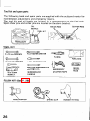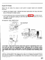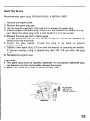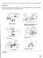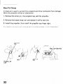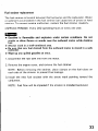
1
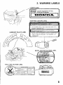
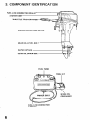
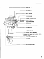
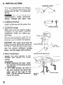
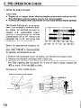
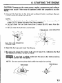
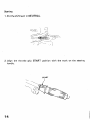
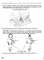
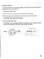
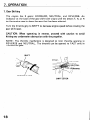
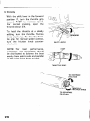
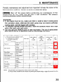
Thank you for purchasing
a Honda Outboard
Motor.
This manual covers operation
and maintenance
of the Honda .Outboard
Motor. All information
in this publication
is based on the latest product
information
available at the time of approval for printing.
Honda Motor Co., Ltd. reserves the right to make changes at any time without
notice and without incurring any obligation.
No part of this publication
may be reproduced
without
written
permission.
This manual should, be considered a permanent part of the Outboard
and should remain with the Outboard Motor when it is sold.
Pay special attention
to statements
preceded by the following
B
Indicates a strong possibility
life if instructions are not followed.
CAUTION:
instructions
NOTE:
Indicates a possibility
are not followed.
Gives helpful
of severe personal
of personal
injury
Motor
words:
injury
or loss of
or equipment
damage if
information.
If a problem should arise, or if you have any questions
Motor, consult an authorized Honda dealer.
about the Outboard
m
Honda Outboard Motors are designed to give safe and dependable
service if operated according
to instructions.
Read and understand
the
Owner’s Manual before operating the Outboard Motor. Failure to do so could
result in personal injury or equipment damage
2
CONTENTS
1.
2.
3.
4.
5.
6.
7.
8.
9.
10.
11.
12.
13.
14.
15.
.
...........................................................
SAFETY INSTRUCTIONS
WARNING LABELS ...................................................................
..................................................
COMPONENT IDENTIFICATION
INSTALLATION
.......................................................................
PRE-OPERATION CHECK ...........................................................
STARTING THE ENGINE ............................................................
OPERATION ............................................................................
STOPPING THE ENGINE ..........................
. .................................
.
High altitude operation ............................................................
.......................................................................
MAINTENANCE
.......................................................
TRANSPORTING/STORAGE
TROUBLESHOOTING
................................................................
.....................................................................
SPECIFICATIONS
WIRING DIAGRAM ...................................................................
OPTIONAL PARTS ....................................................................
WARRANTY SERVICE ...............................................................
4
5
6
8
10
13
18
24
24
25
36
38
39
40
41
42
.I. SAFETY lNSTF?UCTUONS
To ensure
safe operation-
0 Understand
the operation
of all controls,
and know how to stop the
engine quickly -READ
THIS OWNER’S MANUAL
CAREFULLY.
0 Do not exceed the boat manufacturer’s
power recommendation,
and be
sure the outboard motor is properly mounted.
0 Never permit anyone to operate the outboard
motor without
proper
instruction.
0 Stop the engine immediately
if any passenger falls overboard.
0 Do not run the motor while the boat is near any person in the water.
0 Exhaust gas contains
poisonous
carbon monoxide.
Never run the outboard motor in a closed garage or confined area.
0 Gasoline is extremely
flammable
and is explosive
under certain conditions. Refuel in a well ventilated
area with the engine stopped.
0 Do not smoke or allow flames or sparks where the engine is refueled or
where gasoline is stored.
0 Do not overfill the fuel tank, and make sure the fuel tank cap is securely
closed after refueling.
0 Be careful not to spill fuel when refueling. Fuel vapor or spilled fuel may
ignite. If any fuel is spilled, make sure the area is dry before starting the
engine.
4
2. WARNING LABELS
FRONT
LABEL
B
Check
oil
Controler
d’huile
obligatoirement
avant
de d8marrer.
level
before
9
starting.
le niveau
1
I
STARTING
II
. DO NOT
. PULL
THEN
PULL
.
PULLEY
LABEL
. NE PAS
II
* TIPER
OPERATE
STARTER
VlTESSES
CAMSHAFT
CAUTION
OTEUR
AV POINT
TANK
CAUTION
ENGINE
AND
UNTIL
COVER
SOME
REMOVED
RESISTANCE
IS FELT.
II
FAST.
EN MARCHE
AVEC
LE LEVIER
DES
MORT.
FONCTIONNER
LE LANCEUR
RECOIL
FUEL
WITH
LIGHTLY
klARD
FAIRE
LABEL
DOUCEMENT.
STARTER
LE MOTEUR
PUIS
LE CAPOT
FORIEMENT
CAUTION
RELEVE
A LA
1
II
LABEL
LABEL
0 ESSUYER
TOUTE
ESSENCE
RENVERSEE.
5.
3. COMPONENT ODENTUFICATOON
FUEL
LINE
STARTER
CONN
GRIP
THROTTLE
FRICTION
ENGINE
GEAR
WATER
GEAR
COVER
OIL
LEVEL
KNOB
LOCK
LEVER
BOLT
INTAKE
OIL
DRAIN
BOLT
FUEL
TANK
TOOL
PRIMER
FUEL LINE
(FEMALE)
6
BULB
CONNECTOR
KIT
\
SPARE OIL
CONTAINER
DIPSTICK
c
_
;;;;;r;-;TTON
SPARE SHEAR
AND COTTER
TILT
PINS
PINS
LEVER
ENGINE
OIL
CLAMP
DRAIN
SCREW
SCREW
ENGINE
SERIAL
NUMBER
* Always list the serial number
ordering parts.
ANTI-CAVITATION
when
PLATE
EXHAUST
WATER
CHECK
TUBE
7
4. INSTALLATION
TRANSOM
It is your responsibility
to choose a
boat suitable for the engine (9.9
horsepower BFlOO, 7.5 horsepower
BF75).
M
Do not exceed the boat
manufacturer’s
power recommendation.
Damage and injury
may
result.
1. Installation
Position
Install at the stern at the center line
of the boat.
2. Installation
Height
Make sure that the transom height
is correct for the motor. Incorrect
installation
height will reduce performance.
The motor should be installed so
that the anti-cavitation
plate is 2-5
cm (0.8-2.0
in) below the bottom
of the boat.
CAUTION:
The water level must be
at least 4 inches above the anticavitation plate, otherwise the water pump
may not receive sufficient
cooling
water, and the engine will overheat.
3. Motor Attachment
Attach
the stern bracket to the
transom
and tighten
the clamp
screws.
CAUTION:
-.
While operating the boat, check
the tightness of the clamp screws
occasionally.
Tie a rope through the hole in
the stern bracket and secure the
other end of the rope to the
boat. This will orevent accidental
loss of the motor.
\
HEIGHT
STERN
I
ANTI-CAVITATION
ROPE
PLATE
t
CENTER
2-5
cm
lO.8-2.0
in.)
4. Motor Angle (In cruising)
Adjust the motor so the axis of the
propeller is parallel with the water
surface.
CAUSES
INCORRECT
BOAT TO “SQUAT”
CAUSES
INCORRECT
BOAT TO “PLOW’
GIVES
CORRECT
MAXIMUM
PERFORMANCE
5. Motor Angle Adjustment
If the propeller axis is not parallel
with the water surface, adjust by
changing the adjusting rod position.
There are four adjusting stages.
USTING
1. Push in (A) the adjusting rod,
twist upwards (B) and pull out to
remove.
2. Inserting the rod in the proper
hole, twist it down to lock.
ROD
3 .A.
-CAUTION:
To prevent damage to
the motor or boat, make sure the
adjusting rod is locked.
ADJUSTING
ROD
TO CHANGE
UNLOCKED
POSITION
. .
.A..~
TO L
Hi
\
LOCKED
POSITION
9
5. PRE-OPERATION CHECK
1. Check the engine’oil
level.
CAUTION:
Engine oil is a major factor affecting engine performance and service life.
Non-detergent and low quality oils are not recommended.
l
Running the engine with insufficient
oil can cause serious engine damage.
l
Use Honda 4-stroke oil, or an equivalent high detergent, premium quality motor oil certified t0 meet or
exceed
U.S. automobile
manufacturer’s
requirements
for Service
Classification
SE or SF. (Motor oils
classified SE or SF will show this
designation on the container.)
Select the appropriate viscosity for
the average temperature
in your
area. SAE low-40 is recommended
for general, all-temperature
use.
1
-30
-20
-10
0
10
20
30
40°C
1. Position the outboard motor vertically, and remove the engine cover.
2. Remove the dipstick and wipe with a clean rag.
3. Reinsert the dipstick, and check the oil level with the dipstick resting on
the filler opening (do not screw in). If the oil level is down toward the
400 cc mark, fill to the 800 cc mark.
Oil capacity:
ENGINE
0.8 II (0.85 US qt)
COVER
LOCK
LEVER
*DIPSTICK
10
2. Check the fuel level
Check the fuel gauge and refill the tank if the fuel level is low.
NOTE: Open the vent knob before removing the fuel filler cap. When the
vent knob is firmly closed, the cap will be difficult to remove.
Use any regular grade automotive
gasoline (unleaded gasoline is preferred)
with a pump octane rating of 86 or higher. Never use an oil/gasoline
mixture or dirty gasoline. Avoid getting dirt, dust or water in the fuel tank.
CAUTION:
Gasoline substitutes
are not
harmful to the fuel system components.
Fuel tank capacity:
l
l
l
l
recommended;
they
may
be
13 II (3.4 US gal)
Gasoline is extremely flammable and explosive under certain conditions.
Refuel in a well ventilated area with the engine stopped.
Do not smoke or allow flames or sparks near the fuel tank and fuel line.
Do not overfill the tank and make sure the filler cap is securely closed
after refueling.
Be careful not to spill fuel when refueling. Fuel vapor or spilled fuel
may ignite. If any fuel is spilled, make sure the area is dry before starting
the engine.
FUEL
S;AUGE
VENT
KNOB
11
3. Check the following
l
l
l
l
12
items.
Check the propeller, the shear pin, and the cotter pin to be sure they are
secure and undamaged.
Check the stern bracket to be sure the motor is securely installed.
Check steering handle operation.
Make sure you have the tool kit and spare parts with you (P. 26).
6. STARTING THE ENGINE
CAUTION:
Damage to the water pump, engine components
and exhaust
system may occur if the motor is operated while the propeller is out the
water.
1. Connect the fuel line to the tank and outboard
the connectors are securely latched.
motor,
as shown.
Be sure
NOTE:
Position the fuel tank so the tank fuel line connector is no more than 1
meter (3.3 ft) below the motor fuel line connector.
l
Do not place the fuel tank more than 2 meters (6.6 ft) away from the
motor.
l
Be sure that the fuel line is not kinked.
l
FEMALE
FUEL
- TO MOTOR
MALE
FUEL LI
-TO
FUEL TANK
LINE
CONNECTOR
CONNECTOR
2. Open the fuel cap vent knob 2 to 3 turns.
3. Squeeze and release the primer bulb until
has reached the motor. Check for leaks.
it feels firm, indicating
that fuel
w
If any fuel is spilled, make sure the area is dry before starting
the engine. Spilled fuel may ignite.
NOTE:
Do not use the primer bulb whiie the engine is running.
PRIMER
BULB
13
Starting
1. Put the shift lever in NEUTRAL.
2. Align the throttle
handle.
grip
START’
position
START
I
14
with
the mark on the steering
3. In temperatures
below 20” C (68” F) use the choke knob.
CHOKE
4. Pull the starter rope slowly
NOTE:
hand.
Do not allow
KNOB
until a resistance is felt, then pull briskly.
the starter
grip to snap back. Return
it slowly
by
15
5. The oil pressure indicator lamp should be on while the engine is running
above idle speed. If the lamp goes off, stop the engine immediately,
check
.the engine oil level and inspect engine for oil leaks.
OIL
6. After starting,
PRESSURE.INDICATOR
be sure water is flowing
LAMP
I
out of the water check tube.
CAUTION:
If water does not flow out, or if steam comes out, stop the
engine. Check to see if the screen in the cooling water inlet is obstructed.
Do not operate the engine until the problem has been corrected.
7. If the choke was used, push it in gradually
16
as the engine warms up.
Emergency
Starting
If the recoil starter is not working
spare starter rope in the tool kit.
properly,
the engine can be started with the
1. Remove the engine cover.
2. Remove the recoil starter by removing
3. Wind the spare rope clockwise
CAUTION:
4. Reinstall
the three 6 mm bolts.
around the pulley to start the engine.
Keep clear of moving parts.
the engine cover.
CAUTION:
Do not operate without
the engine cover. Exposed
parts could cause injury and water may damage the engine.
STARTER
moving
ROPE
17
7. OPERATION
1. Gear Shifting
The engine has 3 gears: FORWARD,
NEUTRAL,
and REVERSE.
An
indicator at the base of the gear shift lever aligns with the letters F, N, or R
on the engine case to show the gear that has been selected.
Turn the throttle
gear shift lever.
grip to SHIFT
to decrease engine speed before moving the
CAUTION:
When operating
in reverse, proceed with
hitting any underwater obstruction
with the propeller.
caution
to avoid
NOTE: The throttle
mechanism is designed to limit throttle
opening
REVERSE and NEUTRAL.
The throttle can be opened to FAST only
FORWARD-gear.
SHIFT
THROTTLE
GRIP
SHIFT
18
LEVER
in
in
2. Steering
To turn to the right, swing the steering handle to the left. To turn to the
left, swing the handle to the right. Boats equipped with a remote control
steering wheel are controlled in the same way as a car.
For smooth steering,
felt when turning.
adjust the steering friction
STEERING
-I\
FRICTION
A
bolt so that a sligh t drag is
BOLT
TO DECREASE
FRICTION
19
3. Cruising
With the shift lever in the forward
position
F, turn the throttle
grip
toward
FAST to increase speed.
For normal
cruising,
open the
throttle about 3/4.
To hold the throttle
at a steady
setting, turn the throttle
friction
knob clockwise. To free the throttle grip for manual speed control,
turn the friction
knob counterclockwise.
SHIFT
performance,
best
NOTE: For
passengers and equipment
should
be distributed
to balance the boat
evenly from side to side and parallel
to the water from front to back.
LEVER
FAST
THROTTLE
GRIP
ICTION
TO DECREASE
FRICTION
20
KNOB
4. Tilting
the Motor
Tilt the motor to prevent the propeller and gear case from hitting
when the boat is beached or stopped in shallow water.
bottom
1. Stop the engine and put the shift lever into NEUTRAL.
2. Pull the tilt lever toward you, set the lever in the TILT
raise the engine to either the 32.5” or 72” tilt position.
position,
and
3. To return the engine to the normal RUN position, move the tilt lever
away from you until it stops, tilt the engine slightly, then lower the
engine slowly.
CAUTION:
Do not transport the motor in the tilted
suddenly causing damage to the boat or the motor.
position;
it may drop
EUTRAL
’ TI iT
LEVER
21
CAUTION:
To avoid damaging the motor, use the utmost care when moorwhen its motor is tilted up. Don’t allow the motor to
against the pier or other boats.
ing a boad, especially
strike
CAUTION:
TO avoid damaging
ting or moving the boat.
22
the motor,
never use it as a handle
for lif-
5. Battery
Charging and Lighting
The DC receptacle provides a 12 V, 60 W current for 12 V battery charging
and lighting. The circuit is protected by a 5 A fuse that is accessible by
removing the engine cover.
An electrical plug for the DC receptacle is supplied
your charging or lighting cord to this plug.
with your motor. Wire
B
Batteries produce explosive gases. Keep sparks, flames, and
cigarettes away. To prevent the possibility
of creating a spark near the
battery, connect the charging cords first to the battery, then to the
outboard motor, and disconnect the charging cords first at the outboard
motor.
CAUTION:
Connect the positive battery terminal to the positive charging cord. Do
not reverse the charging cords, or serious damage to the outboard
motor’s charging circuit and/or battery may occur.
l
When not in use, cover the DC receptacle with the rubber cover to keep
it dry and clean.
l
DC RECEPTACLE
FUSE
RUBBER
(5A)
COVER
23
8. STOPPING THE ENGONE
1. Turn the throttle
grip to SHIFT and move the shift lever to NEUTRAL.
2. Push the stop button
until the engine stops running.
STOP
l
High altitude
BUTTON
operation
At high altitude, the standard carburetor air-fuel mixture
ly rich. Performance
will decrease, and fuel consumption
will be excessivewill increase.
High altitude performance
can be improved by installing a smaller diameter
main fuel jet in the carburetor
and readjusting
the pilot screw. If you
always operate the outboard
motor at altitudes
higher than 6,000 feet
‘above sea level, have your authorized
Honda Outboard Motor dealer perform these carburetor
modifications.
Even with suitable carburetor jetting, engine horsepower
will decrease approximately
3.5% for each 1,000 foot increase in altitude. The affect of
altitude on horsepower
will be greater than this if no carburetor
modification is made.
CAUTION:
Operation of the outboard motor at an altitude lower than the
carburetor
is jetted for may result in reduced performance,
overheating,
and serious engine damage caused by an excessively
l.ean air/fuel mixture.
24
9. MAINTENANCE
Periodic maintenance and adjustment are important to keep the motor in the
best operating condition.
Inspect or service as scheduled below.
B
Shut off the engine before performing
any maintenance.
If the
engine must be run, make sure the area is well ventilated.
The exhaust
contains poisonous carbon monoxide gas.
CAUTION:
If the engine must be run, make sure there is water at least 4 inches above
the cavitation
plate, otherwise the water pump may not receive sufficient
cooling water, and the engine will overheat.
l
To maintain.cooling
system efficiency, flush the outboard motor with fresh
water after each use in salt water.
l
Use only genuine HONDA parts or their equivalent. The use of replacement
parts which are not of equivalent quality may damage the motor.
l
ULAR SERVICE PERIOD
formed at every mdlcated
r operatmg
hour interval.
ichever comes first.
month
Ref.
Page
P. 27
P. 27
P. 28
P. 28
Gear case oil
P. 29
P. 33
P. 32
P. 31
NOTE:
I1 I Lubricate
more
frequently
when
(2) These
items
should
be serviced
proper
tools
and
is mechanically
used
by an
in salt water.
authorized
Honda
proficient.
See
the
dealer,
Honda
Shop
unless
the
owner
has
the
Manual.
25
Tool kit and spare parts
The following
tools and spare parts are supplied with the outboard motor for
maintenance, adjustment, and emergency repairs.
The tool kit and oil bottle are located in a compartment
on the fuel tank.
Spare shear pins and cotter pins are located on the stern bracket.
OIL
SHEAR
COTTER
PINS
PINS
L KIT
TOOL
KIT
-
-
9 x 12 mm WRENCH
FLAT
SCREW
DRIVER
/=qq
:
PLIERS
-
TOOL
-
10 x 12 mm WRENCH
FLAT
BAG
SCREWDRIVER
fIzizE%
8 mm WRENCH
PHILLIPS
lzLz-30
3
c
a
SCREWDRIVER
HANDLE
18 x 19 mm
SOCKET
WRENCH
SCREWDRIVER
EMERGENCY
STARTER
ROPE
SPARE
SPARK
PLUG
FLUSH KIT (See P. 28)
SPRING
26
CLIP
RUBBER
FITTING
Engine Oil Change
Drain the oil while
draining.
the engine
is still warm to assure rapid and complete
1. Remove the engine cover. .Remove the drain screw and filler cap, and drain
the oil. Reinstall the drain screw.
2. Fill the crankcase with the recommended oil (see page 10) and check the oil
level with the dipstick resting on the filler opening (do not screw in). Fill to
the 800 cc mark.
Oil capacity:
0.8 R (0.85 US qt)
OIL
FILLER
CAP
SCREW
Used motor oil may cause skin cancer if repeatedly left in conCAUTION:
tact with the skin for prolonged
periods. Although
this is unlikely unless
you handle used oil on a daily basis, it is still advisable to thoroughly
wash
your hands with soap and water as soon as possible after handling used
oil.
NOTE: Please dispose of used motor oil in a manner that is compatible
with the environment.
We suggest you take it in a sealed container to your
local service station for reclamation.
Do not throw it in the trash or pour it
on the ground.
27
Gear Oil Check/Change
Oil Level Check
Check the oil level when engine is in the vertical
screw and see if oil flows out. If no oil comes out,
hole until the oil starts to flow out through the
water in the oil, the water will flow out first when
or the oil will be a milky color.
position. Remove the level
fill through the drain screw
level screw hole. If the.re is
the drain screw is removed,
Oil Change
Remove the level screw and drain screw to drain the oil. Inject oil through the
drain screw hole until it starts flowing out through the level screw hole.
Reinstall and tighten the level screw and drain screw securely.
CAUTION:
authorized
If water is detected
Honda dealer.
Recommended
Oil capacity:
28
Oil:
in the oil, the unit should be inspected by an
API standard (G L-4 or G L-5)
SAE 90 outboard motor gear oil
0.23 II (0.49 US pt) ,
Spark Plug Service
Recommended
1.
2.
3.
4.
5.
6.
7.
8.
spark plug: DR-5HS (NGK),
XlGFSR-U
(ND)
Remove the engine cover.
Remove the spark plug cap.
Use the wrench supplied in the tool kit to remove the spark plug.
Visually inspect the spark plug. Discard it if the insulator is cracked or chipped. Clean the spark plug with a wire brush if it is to be reused.
Measure the plug gap with a feeler gauge.
The gap should be 0.6-0.7 mm (0.024-0.028
in). Correct as necessary by
bending the side electrode.
Attach
the plug washer. Thread the plug in by hand to prevent
cross-threading.
Tighten a new spark plug l/2 turn with the wrench to compress the washer.
If you are reusing a plug, it should only take l/8-1/4
turn after the plug
seats.
Reinstall the engine cover.
CAUTION:
The spark plug must be securely tightened. An improperly
can become very hot and possibly damage the engine.
l
Never use a spark plug with an improper heat range.
l
tightened
PLUG GAP
0.6-0.7
mm
(0.024-0.028
/
plug
in)
WRENCH+
29
Cleaning and Flushing
After each use in salt water or dirty
outboard motor.
water,
thoroughly
clean and flush the
1. Wash the outside of the outboard motor with clean, fresh water.
2. Flush the cooling system, using the Honda flush kit supplied with the
outboard motor.
a. Attach a hose from a fresh water faucet to the flush kit hose coupler.
b. Remove the propeller, and clip the flush kit rubber fitting over the water
intake as shown.
c. Turn on the fresh water supply to the hose.
d. Start the engi’ne and run in neutral for 10 minutes.
l
For safety, the propeller
l
Be sure the outboard
unattended
must be removed.
motor
is securely
mounted,
and do not
leave it
while running.
CAUTION:
Running the engine without water can cause serious engine
damage due to overheating.
Be sure that water flows from the water
check tube while the engine is running.
If not, stop the engine and
determine the cause of the problem.
KIT
WAiER
HOSE
30
Lubrication
Wipe the outside of the engine with a cloth
anti-corrosion
grease to the following parts:
CLAMP
SCREWS
dipped
THROTTLE
CABLE
SHIFT SHAFT AND
HANDLE
SWIVEL
PIVOT
marine
AND PIVOT
PIVOT
’
\’
CASE
PROPELLER
TILT
NOTE: Apply
penetrate.
in oil. Apply
SHAFT
\
/
LINKAGE
anti-corrosion
oil
to
pivot
surfaces
where
grease cannot
31
Shear Pin Change
A shear pin is used to protect the propeller
when the propeller strikes an obstruction.
1. Remove the cotter pin, the propeller
and drive mechanism
from damage
cap, and the propeller.
2. Remove the broken shear pin and replace it with a new one.
3. Install the propeller,
then install the propeller
cap finger tight.
4. Install a new cotter pin, and spread the ends as shown in the illustration.
COTTER
PIN
J
I
PIN
‘PROiELLER
CAP
32
COTTER
PIN
SPARE
SHEAR PINS
AND COTTER
PINS
Fuel strainer
replacement
The fuel strainer is located between
the fuel pump and the carburetor.
Water
or sediment
accumulated
in the fuel strainer can cause loss of power or hard
starting.
To prevent
engine malfuction,
replace the fuel strainer
regularly.
((SERVICE
l
l
l
l
PERIOD))
Every
200
operating
hours
or every
one year.
Gasoline is flammable
and explosive
under certain conditions.
Do not
smoke or allow flames or sparks near the outboard motor while draining
fuel.
Always work in a well-ventilated
area.
Be sure that any fuel drained from the outboard motor is stored in a safe
container.
Wipe up any spilled gasoline at once.
1. Disconnect
2. Remove
the fuel tank
the engine
cover,
NOTE:
Before removing
each side of the strainer
3. Install the
carburetor.
NOTE:
new
Fuel flow
fuel
will
line from
the motor.
and remove
the fuel strainer.
the strainer,
place clamps
to prevent
fuel leakage.
strainer
with
be impeded
the
arrow
if the strainer
mark
on the
pointing
is installed
fuel
tubes
toward
on
the
backward.
.
33
4. Remove the clamps used to close the fuel tubes. Connect
the fuel tank
to the motor. Turn the fuel tank vent knob to the ON position,
pump
primer bulb, and check for leaks.
Contact
an authorized
Honda dealer
accumulated
in the fuel strainer.
if you find
excessive
water
or sediment
FUEL STRAINER
The
the
CARBURETOR
34
line
the
arrow
mark
indicates
fuel
flow
direction.
Servicing a Submerged Motor
A submerged motor must be serviced immediately
after it is recovered from
the water in order to minimize corrosion.
If there is a Honda outboard
motor dealership nearby, take the motor
immediately
to the dealer. If you are far from a dealership, proceed as
follows:
1. Remove the engine cover, and rinse the motor with fresh water to remove
salt water, sand, mud, etc.
2. Loosen the carburetor
drain screw (p. 36), drain the contents of the
carburetor into a suitable container, then retighten the drain screw.
3. Change the engine oil (p. 27). If there was-water in the engine crankcase, or
the used engine oil showed’signs
of water contamination,
then a second
engine oil change should be performed after running the engine for l/2
hour.
4. Remove the spark plugs. While pressing the engine stop button, pull the
recoil starter several times to completely expel water from the cylinders.
CAUTION:
l
When cranking the engine with an open ignition circuit (spark plugs
removed from the ignition
circuit),
keep the engine stop button
depressed to prevent electrical damage to the ignition system.
l
If the motor was running when it submerged, there may be mechanical
damage, such as bent connecting rods. If the engine binds when cranked,
do not attempt to run the motor until it has been repaired.
5. Pour a teaspoon of engine oil. into each spark plug hole, then pull the recoil
starter several times to lubricate the inside of the cylinders. Reinstall the
spark plugs.
6. Attempt to start the engine.
l
If the engine fails to start, remove the spark plugs, clean and dry the
electrodes, then reinstall the spark plugs and attempt to start the engine
again.
l
If the engine starts, and no mechanical damage is evident, continue to
run the engine for l/2 hour or longer (be sure the water level is at least 4
inches above the cavitation plate).
7. As soon as possible, take the motor to a Honda outboard motor dealer for
inspection and service.
10. TRANSPORTING/STORAGE
1. Disconnect the fuel line and install
close the fuel cap vent knob.
the cap on the engine fuel inlet. Firmly
CAP
FUEL’INLET
FUEL
LINE
COb.iNECTbk
2. Loosen the carburetor
drain screw, and drain the gasoline into a suitable
container. After draining, retighten the drain screw.
B
Be careful
not to spill fuel.
Fuel vapor or spilled fuel may ignite.
CAUTION:
In cold weather, to prevent ice from forming inside the water
pump, pull the recoil starter several times to flush the water out.
DRAliv
36
SCdEW
-
3. To carry, hold the motor by the carrying
handle, or hold by the carrying
handle and engine cover lock lever as shown here. Do not carry by the
engine cover.
4. Transport and store the motor either vertically or horizontally,
as shown
here, with the steering handle raised.
Vertical transport or storage: Attach the stern bracket to a stand.
Horizontal
transport
or storage: Rest the motor on the case protector
(steering handle side of the motor).
CAUTION:
Any other transport
l
5. Store the outboard
or storage position
may cause damage or oil leakage.
motor in a clean, dry area.
NOTE: Before storing, clean, flush,
described on pages 30 and 31.
and lubricate
the outboard
CASE
motor as
PROTECTOR
37.
1 ‘I. TROUBLESHOOTONG
Engine Will Not Start:
1.
2.
3.
4.
5.
Is the shift lever in neutral?
Is there fuel in the fuel tank?
Is the fuel cap knob turned to ON?
Is the fuel system primed by squeezing the primer bulb?
Is fuel reaching the carburetor?
Loosen the carburetor
float bowl.
drain screw to see if there is fuel in the carburetor
w
If any fuel is spilled, make sure the area is dry before testing the
spark plug or starting the engine. Fuel vapor and spilled fuel may ignite.
6. Are the spark plugs firing?
and inspect ‘the spark plugs. Clean and dry the plugs, and check
the electrode gap (p. 29).
b. Install both spark plugs in their caps, and ground the side electrodes to
each other or to any engine ground.
c. Pull the recoil starter briskly, and see if the plugs spark.
d. If the spark plugs are OK, reinstall them, and try to start the engine.
a. Remove
Engine Overheats:
1. Is the water intake screen clogged?
2. Is the thermostat faulty?
38
12. SPECIFICATIONS
Item
Specification
7.5 horse power
9.9 horse power
output
Full throttle
1 Enaine
4.800-5.200
5.000-5.700
range
tvoe
1 4-stroke
riisolacement
tappet
Soark
olua aao
Starter
system
Ignition
clearance
OHC in-line
0.06-0.1
Recoil
Lubrication
pump
API standard (GL-4/5)
SAE 90 outboard
motor
system
0.8 Q (0.85
Diaphragm
Fuel
Automotive
capacity
low-40
gear oil
US qt)
0.23 Q (0.49
US pt)
thermostat
exhaust
(NGK).
XlGFSR-U
I
(ND)
type fuel pump
gasoline
(91 research
octane,
86 pump
octane)
13 Q (3.4 US gal)
equipment
Bar handle
) 2-stage adjustment
angle
Angle
of rotation
Overall
length
Height from
anticavitation
(SE or SF) SAE
I
Underwater
1 DR-5HS
Fuel pump
Tilt
lubrication
Gear case:
Water cooling with
(volumetric
pump)
system
Steering
pressure
API standard
1 12V-60W
~luas
Tank
in)
Engine:
Engine:
1 D.C. output
Exhaust
in)
starter
Gear case:
1 Soark
I
mm (0.002-0.004
Trochoid
oil
Oil capacity
Cooling
cvlinder
C.D.I.
system
Specified
twin
cu in)
1 0.7 mm (0.028
system
(BF75)
(BFlOO)
rpm (BF751
rpm (BFlOO)
I 197 cc (12.0
Valve
(Maximum)
(Maximum)
x height
45”
x width
stern bracket
plate
Standard Propeller
(No. of blades-diameter
to
x pitch)
(both
(32.5”
and 72”)
sides)
S Model
L Model
515 x 1010
515 x 1160
x 315 mm (20.28
x 315 mm (20.28
S Model
L Model
422 mm (16.61
572 mm (22.52
3 - 240 x 220 mm (9-l/2
Gear change
Forward
Dry weight
S Model
L Model
- Neutral
x 12.4 in)
x 12.4 in)
in)
in)
x S-5/8
- Reverse
34.0 kg (74.97
35.0 kg (77.18
x 39.76
x 45.67
in)
(dog type)
lb)
lb)
39
13. WIRING DIAGRAM
Component
I SP
Identification
1
w
Ignition
ESw
1 FW
Spark
’ Engine
1
Plug
Wire color
I
Coil
Stop button
Fly Wheel
I
1 BI
1
Black
I
Y
I
Yellow
1 Bu
1
Blue
G
Red
Br
Brown
-W
1
White
0
I
Oranae
BllW
1
NSw
40
1 Neutral
Switch
I
Green
R
Black/White
I
I
14. OPTIONAL PARTS
GEAR
VERTICAL
STARTER
OIL
EMERGENCY
STOP SWITCH
ENGINE
ENGINE
COVER
41
15. WARRANTY
Owner
SERWOCE
Satisfaction
Your satisfaction
and goodwill
are important
to your dealer and to us. All
Honda warranty details are explained in the Distributor’s
Limited Warranty.
Normally,
any problems concerning
the product will be handled by your
dealer’s service department.
If you have a warranty
problem that has not
been handled to your satisfaction,
we suggest you take the following
action:
l
l
Discuss your problem with a member of dealership management.
Often
complaints
can be quickly resolved at that level. If the problem has
already been reviewed with the Service Manager, contact the owner of
the dealership or the General Manager.
If your problem still has not been resolved to your satisfaction,
contact
the Power Equipment
Customer
Relations
Department
of American
Honda Motor Co., Inc.
American
Honda Motor Co., Inc.
Power Equipment
Customer Relations
P.O. Box 50
Gardena, California .90247-0805
Telephone:
(213) 604-2400
We will need the following
information
- Your name, address, and telephone
- Product model and serial number
- Date of purchase
- Dealer name and address
- Nature of the problem
Department
in order to assist you:
number
After reviewing
all the facts involved,
you will be advised of what action
can be taken. Please bear in mind that your problem will likely be resolved
at the dealership,
using the dealer’s facilities, equipment,
and personnel, so
it is very important
that your initial contact be with the dealer.
Your purchase
of a Honda product is greatly appreciated
by both your
dealer and American Honda Motor Co., Inc. We want to assist you in every
way possible to assure your complete satisfaction
with your purchase.
42
Current customer service contact information:
Your owner's manual was written to cover most of the questions you might ask about
your Honda. Any questions not answered in the owner's manual can be answered by
your Honda dealer. If your dealer doesn't have an immediate answer, they should be
able to get it for you.
If you have a difference of opinion with your dealer, please remember that each
dealership is independently owned and operated. That's why it's important to work to
resolve any differences at the dealership level. If the service personnel are unable to
assist you, please discuss your concerns with the dealer management such as the
Service Manager or the dealership's owner.
If you need to contact American Honda regarding your experiences with your Honda
product or with your dealer, please send your comments to the following address:
American Honda Motor Co., Inc.
Marine Division
Customer Relations Office
4900 Marconi Drive
Alpharetta, GA 30005-8847
Or telephone: (770) 497-6400 M-F, 8:30 am - 7:00 pm EST
When you write or call, please provide the following information:
•
Your name, address and telephone number (complete with area code)
•
Model and complete serial number
•
Date of purchase
•
Name and location of the selling dealer
•
Name and location of the servicing dealer (if different)
•
A detailed description of your concerns
MEMO
43
MEMO
44