1
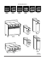
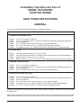
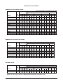
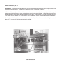
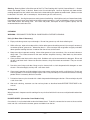
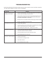
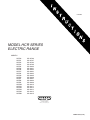
RANGES
MODEL HCR SERIES
ELECTRIC RANGE
MODELS
HCR40
HCR41
HCR42
HCR43
HCR44
HCR45
HCR46
HCR47
HCR48
HCR49
HCR50
HCR51
HCR56
HCR58
HCR401
HCR411
HCR421
HCR431
HCR441
HCR561
ML-43796
ML-43797
ML-43798
ML-43799
ML-43800
ML-43801
ML-43802
ML-43803
ML-43804
ML-43805
ML-43806
ML-43807
ML-43808
ML-43809
ML-43810
ML-43811
ML-43812
ML-43813
ML-43814
ML-43815
EXECUTIVE OFFICES
701 RIDGE AVENUE
TROY, OHIO 45374-0001
FORM 18504 (10-92)
HCR RANGE MODELS
HCR40
HCR46
HCR401
HCR41
HCR47
HCR411
HCR42
HCR48
HCR421
HCR43
HCR49
HCR431
HCR50
HCR56
HCR561
HCR58
HCR441
HCR44
HCR40
HCR51
HCR45
HCR46
PL - 50911
© HOBART CORPORATION, 1992
–2–
TABLE OF CONTENTS
PAGE
GENERAL ........................................................................................................................................................... 4
INSTALLATION ................................................................................................................................................... 5
UNPACKING .............................................................................................................................................. 5
LOCATION .................................................................................................................................................. 6
LEVELING .................................................................................................................................................. 5
BATTERIED RANGES ............................................................................................................................... 5
ELECTRICAL CONNECTIONS ................................................................................................................. 5
OPERATION ....................................................................................................................................................... 7
BEFORE FIRST USE ................................................................................................................................. 7
TOP SURFACE ELEMENTS AND CONTROLS ...................................................................................... 7
OVEN CONTROLS .................................................................................................................................... 8
USING THE RANGE TOP ......................................................................................................................... 9
USING THE OVEN ..................................................................................................................................... 9
OPERATING HINTS ................................................................................................................................ 10
COOKING TIPS ........................................................................................................................................ 10
CLEANING ................................................................................................................................................ 11
TROUBLESHOOTING ...................................................................................................................................... 12
–3–
Installation, Operation and Care of
MODEL HCR SERIES
ELECTRIC RANGE
SAVE THESE INSTRUCTIONS
GENERAL
The various Hobart Model HCR Series Ranges are equipped as follows:
MODEL
EQUIPPED WITH
RANGE WITH STANDARD OVEN
HCR40
HCR41
HCR42
HCR43
HCR56
HCR58
(3) 12" x 24" hot tops, 5 KW each
(2) 12" x 24" hot tops and (2) 91/2" diameter round French hot plates (or high speed elements)
36" wide griddle top
(6) 91/2" diameter round French hot plates (or high speed elements)
(2) 12" x 24" hot tops and (2) 91/2" diameter round high speed elements
24" griddle top and (2) 91/2" diameter round French hot plates (or high speed elements)
EXPANDO UNITS
HCR44
HCR45
HCR50
HCR51
Full body expando unit with (1) 12" x 24" hot top
Full body expando unit with (2) 91/2" diameter round French hot plates (or high speed elements)
Modular (table) unit with (1) 12" x 24" hot top
Modular (table) unit with (2) 91/2" diameter round French hot plates (or high speed elements)
MODULAR (TABLE) RANGES
HCR46
HCR47
HCR48
HCR49
(3) 12" x 24" hot tops, 5 KW each
(2) 12" x 24" hot tops and (2) 91/2" diameter round French hot plates (or high speed elements)
36" wide griddle top
(6) 91/2" diameter round French hot plates (or high speed elements)
RANGE WITH CONVECTION OVEN
HCR401
HCR411
HCR421
HCR431
HCR441
HCR561
(3) 12" x 24" hot tops, 5 KW each
(2) 12" x 24" hot tops and (2) 91/2" diameter round French hot plates (or high speed elements)
36" wide griddle top
(6) 91/2" diameter round French hot plates (or high speed elements)
24" griddle and (2) 91/2" diameter round French hot plates (or high speed elements)
(2) 12" x 24" hot tops and (2) 91/2" diameter round high speed elements
Hot tops are provided with clean-out grooves at left and right edges of range tops. Hot tops are not recommended
for griddle work.
Optional high speed round tubular surface units are available in place of round French hot plates for use with
208 or 240 volt ranges only. High speed round tubular surface units are not recommended for stock pot work.
–4–
All ranges are equipped with adjustable 6" legs. Optionally, they may be equipped with no legs (for masonry base
mounting) or a 4" toe base in place of legs. Ranges with ovens are equipped with one oven rack. One additional
oven rack is available as an option. All full size free standing and modular ranges are provided with two drawers
under the cooking tops; the left drawer is a baffled grease drawer, and the right drawer is a warming drawer.
INSTALLATION
UNPACKING
Immediately after unpacking the range, check it for possible shipping damage. If the range is found to be
damaged after unpacking, save the packing material and contact the carrier within 15 days of delivery.
Prior to installation, verify that the electrical service agrees with the specifications on the data plate which is
located on the front breaker cover door.
LOCATION
Position the range in its final installation position. Refer to the data plate for required clearances adjacent to
combustible and non-combustible construction. When a broiler is installed over the range, refer to its data plate
for clearance requirements as well as the range data plate. Install the range so that the conduit can be placed
into the bottom entrance.
LEVELING
Using a carpenter level placed on top of the range, adjust the feet so the range is level from front to back and
from side to side.
BATTERIED RANGES
You can place any combination of range models, along with expando units, in a battery. Modular models may
be arranged in a battery as well. Spreader plates (available from Hobart Corporation) should be used when
models are to be positioned close together in order to deflect grease which falls between ranges.
ELECTRICAL CONNECTIONS
WARNING: ELECTRICAL AND GROUNDING CONNECTIONS MUST COMPLY WITH THE APPLICABLE
PORTIONS OF THE NATIONAL ELECTRICAL CODE AND/OR OTHER LOCAL ELECTRICAL CODES.
WARNING: DISCONNECT ELECTRICAL POWER SUPPLY AND PLACE A TAG AT THE
DISCONNECT SWITCH TO INDICATE THAT YOU ARE WORKING ON THE CIRCUIT.
Bring conduit containing the proper supply wire (size and type in accordance with latest edition of the National
Electrical Code ANSI/NFPA-70) to the range through the 2" hole located in the bottom of the range. On modular
(table) ranges and expando units, the conduit enters the range through the clearance hole located in the back
of the range. Use wire suitable for 75°C on ranges carrying more than 80 amps.
Connect the supply leads to the terminal block and the green grounding lead to the labeled ground lug.
–5–
ELECTRICAL DATA CHARTS
RANGES WITH STANDARD OVENS
"N/A" RANGES NOT AVAILABLE 480 VOLT
3 PHASE LOAD
TOTAL KW PER PHASE
KW 208V 240V 480V
MODEL
CONN. X-Y Y-Z X-Z
HCR40,42
21.7 7.7
5
9
HCR40,42 / HCB48 27.7 10.7
8
9
HCR46,48
15
5
5
5
HCR46,48 / HCB48
21
8
8
5
HCR41,58
20.7 7.7
5
8
HCR41,58 / HCB48 26.7 10.7
8
8
HCR47
14
5
5
4
HCR47 / HCB48
20
8
8
4
HCR43
18.7 6.7
4
8
HCR43 / HCB48
24.7 9.7
7
8
HCR49
12
4
4
4
HCR49 / HCB48
18
7
7
4
HCR56
20.7 7.7
5
8
HCR56 / HCB48
26.7 10.7
8
8
X
70
82
42
54
65
78
38
50
61
74
33
46
65
78
208V
Y
53
78
42
67
53
78
42
67
45
70
33
58
53
78
NOMINAL AMPS PER LINE WIRE
3 PHASE
1 PHASE
240V
480V
208V 240V 480V
Z
X
Y
Z
X
Y
Z
XYZ XYZ XYZ
58
60
46
51
30
23
25 104 90
45
71
71
68
61
30
34
36 133 115 N/A
42
36
36
36
18
18
18
72
63
31
54
47
58
47
18
29
29 101 88
44
54
57
46
47
28
23
24
99
86
43
67
68
68
58
28
34
34 128 111 N/A
38
33
36
33
16
18
16
67
58
29
50
43
58
43
16
29
27
96
83
42
50
53
39
43
19
27
22
90
78
39
63
64
60
54
27
30
33 119 103 N/A
33
29
29
29
14
14
14
58
50
25
46
40
51
40
14
25
25
87
75
38
54
57
46
47 N/A N/A N/A 99
86 N/A
67
68
68
58 N/A N/A N/A 128 111 N/A
RANGES WITH CONVECTION OVENS
3 PHASE LOAD
TOTAL KW PER PHASE
KW 208V,240V & 480V
MODEL
CONN. X-Y Y-Z X-Z
X
HCR401,421
22
6.2 6.2 9.6
66
HCR401,421/HCB48 28
9.2 9.2 9.6
78
HCR411,441
21
6.2 6.2 8.6
62
HCR411,441/HCB48 27
9.2 9.2 8.6
74
HCR431
19
5.2 5.2 8.6
58
HCR431/HCB48
25
8.2 8.2 8.6
70
HCR561
21
6.2 6.2 8.6
62
HCR561/HCB48
27
9.2 9.2 8.6
74
NOMINAL AMPS PER LINE WIRE
3 PHASE
1 PHASE
208V
240V
480V
208V 240V
Y
Z
X
Y
Z
X
Y
Z
XYZ XYZ
51
66
57
45
57
29
22
29 106 92
76
78
68
66
68
34
33
34 135 117
51
62
54
45
54
27
22
27 101 87
76
74
64
66
64
32
33
32 130 112
43
58
50
37
50
25
19
25
91
79
68
70
61
59
61
30
29
30 120 104
51
62
54
45
54 N/A N/A N/A 101 87
76
74
64
66
64 N/A N/A N/A 130 112
EXPANDO UNITS
MODEL
HCR44,50
HCR45,51
3 PHASE LOAD
TOTAL KW PER PHASE
KW 208V 240V 480V
CONN. X-Y Y-Z X-Z
5
—
—
5
4
2
2
—
X
—
8
NOMINAL AMPS PER LINE WIRE
3 PHASE
1 PHASE
208V
240V
480V
208V 240V 480V
Y
Z
X
Y
Z
X
Y
Z
XYZ XYZ XYZ
—
—
—
—
—
—
—
—
24
21
11
17
8
7
14
7
3.6 7.2 3.6
20
17
8.3
"HCB48" in above charts denotes a Model HCB48 Charbroiler installed on range.
–6–
OPERATION
WARNING: THE RANGE AND ITS PARTS ARE HOT. USE CARE WHEN OPERATING, SERVICING AND
CLEANING THE RANGE.
BEFORE FIRST USE
Clean off the rust preventive compound on the surface units with a cloth dampened with a grease solvent. Wipe
with a clean, damp cloth, then dry thoroughly.
Seasoning
The cast iron surface plates must be seasoned. To do this, grease the top, then turn the element switches to
LO (or thermostat to 300°F) and allow the plates to heat up gradually for about 2 hours. Repeat this procedure
a second time before regular use. Seasoning the surface plates will deter cracking of the cast iron and ensure
a longer life.
TOP SURFACE ELEMENTS AND CONTROLS (Fig. 1)
CAUTION: Do not continuously operate surface units at maximum temperature; this is for occasional
use only. This practice contributes not only to costly operation and waste of energy, but also to rapid
deterioration of the heating elements and castings.
Element Switches — control and maintain heat to surface elements.
Element Indicator Lights — when lit, indicates power is being supplied to the element.
There are 3 different types of plates that may be used in the HCR Series Ranges.
PLATE & SIZE
Hot Top
12" X 24"
91/2" Dia. French
Hot Plates
(or Optional
Hi-Speed
Elements)
91/2" Dia.
Hi-Speed
Elements
Griddle Top 36"
Griddle Top 24"
USED IN
MODELS
HCR40, HCR41,
HCR44, HCR46,
HCR47, HCR50,
HCR56, HCR401,
HCR411, HCR561
HCR41, HCR43,
HCR45, HCR47,
HCR49, HCR51,
HCR58, HCR411,
HCR431, HCR441
HCR56, HCR561
HCR42, HCR48,
HCR421
HCR58, HCR441
CONTROLS
Thermostat provides control of a single
element rated at 5 KW. Indicator light
(next to thermostat) is ON when thermostat
calls for heat and goes OFF when
desired temperature is reached.
Infinite switch (3-heat switch in 480 V.
models) provides (according to its setting)
a varying percent (about 7-100%) of its total
input to the elements. Rated at 2 KW.
Infinite switch provides (according to its
setting) a varying percent (about 7-100%) of
its total input to the elements. Rated at 2 KW.
(3) thermostats, each with its own indicator
cycling light.
(2) thermostats with individual indicator lights.
TEMP.
RANGE
340 to 800°F
*
175-550°F
175-550°F
*The 91/2" diameter French hot plates are energy saving units. A separate thermostat is built into each plate.
When a plate's dial is set at the top range of the infinite switch and a pan or pot containing food is placed on the
plate, the plate delivers 2,000 watts at a temperature lower than 800°F. When the cooking utensil is removed
or boils dry, heat is no longer carried from the unit and the temperature rises. When the plate reaches from 820°F
to 850°F, wattage is cut back to 950 watts, a 52.5% reduction.
–7–
OVEN CONTROLS (Fig. 1)
Thermostat — (located on the right side of the switch panel) controls and maintains oven temperature around
the desired set temperature. Temperature range of the oven is from 175°F to 550°F.
3-Heat Switches — (two switches which are located one on each side of the thermostat) control the top and
bottom oven heating elements, thereby controlling the rate of temperature build-up. At HI position, the maximum
element power is utilized (both elements connected in parallel), at MED position, only one of the two elements
is on (about one-half power), and at LO position, the two elements are on in series (about one-quarter power).
Oven Indicator Light — (located next to the thermostat) when lit, indicates the thermostat is calling for heat and
when OFF, indicates the desired temperature is reached.
Model HCR40 Shown
Fig. 1
–8–
USING THE RANGE TOP
Use the high setting to bring food quickly up to its cooking temperature, then reduce to the actual cooking
temperature. During traffic lulls, reduce plate temperature to idle around 200°F (or set 3-heat switch to MED).
When turned to HI, plates will perform bulk cooking jobs just as rapidly.
12" x 24" Hot Top
Each hot top section is thermostatically controlled. Each may be independently operated at the same or different
temperatures, providing you with selective heat control for general hot top work (sauteing, braising, pan frying
and skillet work). Do not use the hot top for general griddling.
When ready to use the hot top section, wipe the surface clean of all grease and food particles. Position utensils
so that as much of the hot top section area as possible is covered. Set control at dial setting.
French Hot Plate
French hot plates are designed for bulk cooking and stock pot work (up to 20 Qt. stock pots or 9-10" dia. pans).
Stock pots of over 5-gallon capacity are not recommended for continuous use on French hot plate sections. 208/
240 volt units are controlled by infinite heat switches. 480 volt models are controlled by 3-heat switches.
Optional High-Speed Units
High-speed units furnished in lieu of French hot plates on 208 and 240 volt models are controlled by infinite
switches.
Griddle
Use for general griddling (hamburgers, eggs, pancakes, minute steaks, etc.) If using for the first time, griddle
must be seasoned (see BEFORE FIRST USE in this manual).
To use, set dial at desired temperature and allow griddle to preheat (about 7 minutes to reach 350°F). Signal
light will go off when preset temperature is reached. Then load and cook according to recipe, turning foods
halfway through cooking time (unless recipe specifies otherwise).
Each 12" section of the griddle has its own thermostatically controlled heat zone and indicator light. This permits
simultaneous cooking of different foods at different temperatures (such as eggs, 300°F; and bacon, 350°F); or
using the entire griddle top at the same temperature; or using only one or two sections during off-peak periods
for economical operation.
USING THE OVEN
When baking or roasting on one level only, remove rack and place food pans directly on oven deck. When using
rack and deck at the same time, rotate foods halfway through cooking cycle. When baking on the rack, it may
be necessary to set the bottom 3-heat switch at HI.
Preheat oven. Set top and bottom 3-heat switches to HI and thermostat to desired baking temperature. Keep
oven door closed during preheating. While waiting for the oven to preheat, load food products into pans.
When set temperature is reached, allow oven signal light to go on and off at least twice so the oven is thoroughly
heated and will brown baked products evenly. Set 3-heat switches at desired setting. Load oven as quickly
as possible to reduce heat loss from open door. Place pans in center of rack and close door. Do not load small
pans closer than 3" from door. Do not let pans touch the sides or back of the oven or each other.
–9–
When cooking is completed, open oven door and unload product. After oven cools, any spills should be wiped
up as quickly as possible to prevent them from becoming stubborn stains.
OPERATING HINTS
Preheat the oven and surface units to cooking temperature before cooking the product. Become familiar with
the function of the controls and the area of their operation.
Avoid excessive door opening. Also avoid direct air current on the oven.
Use flat-bottomed, straight-sided pots and pans.
Use covers for stock pot work. Water will boil much sooner and much less heat is required for cooking in a
covered container.
Turn high speed elements off a few minutes before cooking is completed to use the heat stored in the element.
After each cooking load, scrape excess food and fat particles off the griddle surface, using a flexible spatula or
wire brush.
COOKING TIPS
Oven
While it is recommended that the 3-heat switches be set to the HI position in order to preheat the oven to the
desired temperature, it is necessary for some baking products to turn the 3-heat switch controlling the top
elements to the MED or LO position in order to reduce the amount of radiant heat applied to the product so that
the top portion of the product will not be burned.
Uneven cooking may be prevented by different settings for the top and bottom oven 3-heat switches. The amount
of heat applied to a product inside the oven is affected not only by the setting of the thermostat and 3-heat
switches, but also by its position inside the oven and the frequency of opening and closing the oven door.
Meat roasting is best performed in a balanced oven; 3-heat switch positions of HI and HI are suggested, with
the thermostat setting at the low temperature recommended by the American Meat Institute and the Department
of Agriculture. Top heat results in a well colored or carmelized finish to meats. When roasting fowl and a heavily
browned appearance is not desired, set the top 3-heat switch at MED or LO. It is recommended that a meat
thermometer be used for all meat roasting operations.
Range Top
Typical cooking operations described below (plus many other types of pot-and-pan work) require quick changes
from high to low heats. With versatile Hobart range tops, you can maintain different sections at different
temperatures and just shift utensils from one section to another when you wish to change the speed of cooking.
Sauteing: Frying in Small Amount of Fat — Heat fat in a frying pan on high heat. When fat is hot, switch to low
heat and add food. Brown one side, turn and brown on second side. A flat-bottomed pan is recommended for
sauteing. If a warped pan is used, food will be unevenly browned.
Pan Broiling: Cooking Meats in Frying Pan — Heat frying pan on high heat. Rub hot pan lightly with fat or suet
to prevent meat from sticking. Add meat and brown on one side. Turn and brown on second side. Pour off fat
as it accumulates.
– 10 –
Stewing: Browning Meat in Small Amount of Hot Fat, Then Cooking with Liquid in Covered Utensil — Season
meats and dredge in flour, if desired. Brown in hot fat and add liquid. Leave on high heat until food reaches
cooking temperature, then switch to low heat for the slow cooking that produces tender foods. (Meats can also
be braised in the oven, with a covered pan, after browning on the surface unit.)
Stock Pot Work — Use high temperature setting to start food boiling. Use high heat only until steam flows freely
from edge of utensil cover, then switch to low heat to continue cooking. If you are following a recipe, start timing
when food reaches the boiling point. On French hot plates, stock pots of over 5-gallon capacity are not
recommended for continuous use.
CLEANING
WARNING: DISCONNECT ELECTRICAL POWER SUPPLY BEFORE CLEANING.
Daily (Or More Often If Necessary)
1. Empty and clean grease trays and troughs. Do not line grease tray with heat-reflecting foil.
2. While still warm, wipe surface tops with a cloth or other grease absorbing material (or scrape if necessary)
to remove spillover, grease, etc., before they burn in. A crust on top of the range looks unsightly and slows
down speed of cooking because it reduces the flow of heat to the utensil.
3. Keep oven clean to prevent smoking. Never allow grease or fat to accumulate. Use an enamel cleaner or
damp cloth. The vitrious enamel on the oven interiors simplifies cleaning. Steel wool may be used for
stubborn spots.
4. Clean stainless steel fronts with a damp cloth. Stubborn soil may be removed with a detergent. Rinse and
dry with a soft clean cloth. Never use abrasive cleaners, sharp instruments or steel wool. They can scratch
the finish.
5. Porcelain oven linings and door linings may be cleaned with a cloth dampened with detergent or oven
cleaner. Rinse thoroughly and dry with a soft clean cloth.
6. Clean oven inspection and light window in the same manner as the liner or with a mild abrasive. Do not use
scouring powder ; it will scratch and fog the glass and it is easy to build up an accumulation of excess scouring
powder which is extremely difficult to remove.
7. Painted surfaces may be cleaned with a cloth dampened with detergent solution. Rinse and wipe dry with
a soft clean cloth.
8. After each cleaning, reseason cast iron surface plates as described under BEFORE FIRST USE in this
manual.
As Required
Wipe plates not in frequent use with cooking oil or any similar oil which will not cause an objectionable odor when
heated.
BLOWER WHEEL (Convection Oven Models Only)
Occasionally, it may be desirable to clean the blower wheel. To do this, remove the fan cover at the rear of the
oven and use a wire brush to remove grease and debris from the fan.
– 11 –
TROUBLESHOOTING
Unsatisfactory browning of the products baked in the oven is often caused by incorrect installation or operation.
The most common problems and their causes are listed below.
PROBLEM
Bottom of product burned top light, or vice versa
Light sides, back, or front
Light front and dark back
Uneven or spotty browning
FORM 18504 (10-92)
CAUSES
1.
Incorrect switch positions. Use next lowest position for overbrowned
surface and/or next highest for light surface.
2.
Oven heated to temperature above proper baking temperature and
insufficient time allowed for cooling. Approximate cooling time for
25°F drop with door open is 10 minutes.
3.
Baking on both rack and deck without switching pans when half done.
4.
Baking at consistently high temperatures.
1.
Frequent door opening.
2.
Insufficient preheat time to saturate oven, or insufficient time allowed
when increasing temperature for different product.
3.
Pans touching oven sides or back. Center pan(s) in oven.
1.
Frequent door opening during baking period. Establish baking time and
leave door closed until time has elapsed.
2.
Vent fan pulling too much air from around the range.
3.
Drafts blowing directly on oven front.
1.
Warped or dented pans.
2.
Accumulation of spillage on deck.
3.
Oven deck not level.
4.
Pans of different finish or color.
– 12 –
PRINTED IN U.S.A.