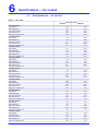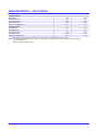
1
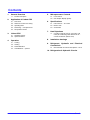
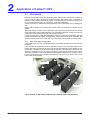
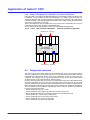
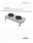
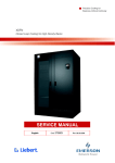
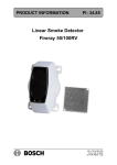
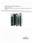
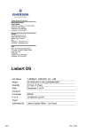
Thermal Management For Business Critical ContinuityTM Liebert ® CRV300DX 50 Hz, 10-21 kW Liebert CRV - PD - 265086- 15.05.2014 A Version PRODUCT DOCUMENTATION Contents Contents 1 Product Description 2 Application of Liebert CRV 3 Liebert CRV 4 Operation 5 Microprocessor Controls 6 Specifications 7 Heat Rejections 8 Installation drawings 9 Refrigerant, Hydraulic and Electrical Connections 10 Refrigeration & Hydraulic Circuits The product conforms to European Union directives 2006/42/EC; 2004/108/EC; 2006/95/EC; 97/23/EC. Units are supplied complete with a Test Certificate Conformity Declaration and Component List. Liebert CRV units are CE marked as they comply with the European directives concerning mechanical, electrical, electromagnetic and pressure equipment safety. Liebert CRV-PD-265086 - 15.05.2014 0-0 Contents 1. General Overview 5. 1.1. Product Description 2. 5.1. iCom Control 5.2. CDL Graphic Display (option) Application of Liebert CRV 2.1. 2.2. 2.3. 2.4. 2.5. First check Selection of Lieber CRV unit(s) Operating limits Positioning - units placement Temperature sensors 6. Liebert CRV Operation 4.1. 4.2. 4.3. 4.4. Cooling Heating Dehumidification Humidification - optional Heat Rejections 7.1. Coupling of Liebert CRV (A-type, 50Hz, CE mark) air conditioning units with remote aircooled condensers (Liebert HCR) 3.1. Standard features 3.2. Optional features 4. Specifications 6.1. Performances - air cooled 6.2. Electric data 6.3. Sound data 7. 3. Microprocessor Controls 8. Installation drawings 9. Refrigerant, Hydraulic and Electrical Connections 9.1. Electrical field connections descriptions-50 Hz 10. Refrigeration & Hydraulic Circuits Liebert CRV-PD-265086 - 15.05.2014 0-1 1 Product Description Product Description 1.1 Product Description The Liebert® CRV is an air cooled full-featured direct expansion Thermal Management unit to be installed within a row of high density computing racks in a “hot-aisle-cold-aisle" configuration. Air heated by the room equipment enters the unit from the hot aisle; it is filtered, cooled, conditioned, and subsequently returned to the cold aisle. Supply air flow direction can be easily modified (via the optional air discharge baffles) to the left side or to the right side or to both directions so it may be placed between the racks or at the end of the row. It maximizes cooling effectiveness, reduces the occurrence of hot spots and improves the overall system efficiency. The Liebert® CRV provides all the necessary functions provided by a standard precision air conditioner including cooling, heating, humidification, dehumidification, air filtration, condensate management, temperature control, alarm functions and data communications. It is targeted for small and medium data centers and it is optimized to ensure maximum cooling capacity in a minimal footprint. The extremely energy efficient components of the system are managed by the Liebert iCOM® Control system. The control monitors the environment in real-time by locating sensors on the inlet of the racks that the unit is cooling. This information allows the unit to optimize its operations in terms of performance and energy efficiency. Service and maintenance are performed through the front and rear of the unit, including all component replacement. All piping and electrical connections are made through the top or bottom of the unit. Liebert CRV-PD-265086 - 15.05.2014 1-1 2 Application of Liebert® CRV Applicationof Liebert® CRV 2.1 First check Before proceeding with Liebert® CRV application please make sure the unit selected is suitable for your site. Liebert® CRV is targeted for small and medium data centers and it is optimized for maximum cooling capacity in a minimal footprint. It is designed for high air inlet temperature (up to 40° C), therefore it is advised to accomplish Hot-Cold aisle configuration. Liebert® CRV is able to modulate the cooling capacity in order to quick adjust to any changing heat load. Liebert® CRV is designed to provide proper control of the room temperature, humidity and air filtration. The specific design of Liebert® CRV is optimized in order to be extremely efficient without providing unnecessary latent cooling (dehumidification) not specifically required for cooling of IT electronic equipments, which enhance the overall cooling system efficiency. In particular cases when a high dehumidification is required, for example in combination with High Density cooling Liebert® XD system, it is suggested to use the Liebert® CRV also in combination with Emerson Network Power Floor mount units (e.g. Liebert® PDX, Liebert® PCW or Liebert® HPM). 2.1.1 Hot-Cold aisle configuration A best practice is to use rows of equipment racks in an alternating arrangement of cold aisles and hot aisles. In the cold aisle, the equipment racks are arranged face to face so the cold air discharged from the Liebert® CRV unit(s) is drawn into the front of the servers and exhausted out through the rear into the hot aisles. Hot aisles are literally hot because the objective of the alternating cold and hot aisle design is to separate the source of cooling air from hot air discharge which returns to the Liebert® CRV unit(s). Therefore, hot and cold aisle should be separated otherwise there would be a mix of hot and cold air and thereby lower the temperature of the air returning to the CRV units, which reduces their usable capacity. CR Hot aisle CR CR CR CR CR CR Cold aisle CR Hot aisle Hot aisle Cold aisle Fig. 2a Example of high density installation with cold aisle and hot aisle alternation 2-1 Liebert CRV-PD-265086 - 15.05.2014 Application of Liebert® CRV 2.1.2 Combination with other Cooling systems Liebert® CRV may be combined with other cooling systems such as underflow CRAC units (e.g. retrofit of current installation) until there is proper setting of both systems without influencing each other. Otherwise there is a risk of cycling or increased power consumption of both systems, in worst case causing malfunction of the units. For details contact Emerson Network Power sales representative. 2.2 Selection of Liebert® CRV unit(s) 2.2.1 Number and size When designing a cooling solution using the Liebert® CRV unit(s), the initial steps are similar to those required to cool a conventional critical space. The total heat load must be calculated, including sensible and latent cooling requirements. These should be increased by the reserve capacity needed for pull- down situations (e.g. after power failure) where the room temperature must be reduced and to cover unexpected increases in the heat load. Consider also redundant capacity, which is usually not in use in the normal operation, but takes duty if any of the running unit(s) fail. So the different steps are: D Check the heat load of IT equipment and apply safety margin if required. D Define size and number of Liebert® CRV units in order to provide enough net sensible cooling capacity to cover the heat load. Typical air inlet temperatures to be considered for normal operation of the unit(s) are between 33° C and 37° C. Please refer also to point 2.2.3 Air Flow Requirements D When N+X (typical N+1) redundancy is required, use more units so if any of the unit(s) fail, the remaining unit(s) will cover the heat load. Always consider the layout of the room when defining number of units, see chapter 2.4 Positioning-unit placement. 2.2.2 Air Flow Requirements Liebert® CRV is optimized to provide precision cooling for IT equipment with temperature raise (delta T) of cooling air passing through the equipment around 15 to 20 degrees Celsius or higher. Such temperature raise is typical for Blade servers and standard pizza servers. For applications with very low delta T, around 10 degrees Celsius, typical for old fashion servers, it is necessary to de-rate cooling capacity of the Liebert® CRV due to higher air flow equipment. In case of application with Cold Aisle Containment (Smart Aisle) it is necessary to carefully investigate the air flow through IT equipment and to define number of Liebert® CRV units in order to provide at least 5% more airflow, excluding redundant unit(s). Otherwise there may occur a situation with negative pressure in the Smart Aisle containment and hot air possibly leaking inside the containment. 2.3 Operating limits The units are designed to operate within working ranges. These limits are referred to new machines or to those that have been correctly installed and serviced. The warranty clauses are no longer valid for any possible damage or malfunction that may occur during or due to operation outside the application values. 2.3.1 For all units (*) From: Room air conditions Temperature 21°C 40°C Humidity ratio 5.5 g/kg 11 g/kg 20 % 60 % Relative humidity Storage conditions Power supply tolerances Liebert CRV-PD-265086 - 15.05.2014 To Temperature - 20°C 50°C V ± 10 % Hz ± 2 2-2 Application of Liebert® CRV 2.3.2 For A units Outdoor temperature: lower limit -20°C To install an air conditioner in places in which external temperature reaches very low values sometime in the year requires some means of control to maintain adequate condensing pressures to ensure proper liquid system opera tion. With low temperatures the refrigerant condensates in pipeline and the liquid tends to fulfill the condenser. It's mandatory to install the following components: 1. NON RETURN VALVE (liquid line) Install a non- return valve in the liquid line directly out of the condenser. It doesn't allow the liquid to come back to the condenser (that means efficiency loss and dangerous stress for the compressor). 2. VARIEX FAN SPEED CONTROL Use Variex fan speed control to regulate the condensing pressure and have a continuous and better subcooling control. It's suggested to have: 3. HORIZONTAL CONDENSER POSITION The condenser horizontal disposition (vertical flow) is necessary to reduce subcooling variations due to direct wind exposure. (very important to have a good subcooling control). For all exceptions contact the Liebert® Sales Representative. Outdoor temperature: higher limit This limit is determined by coupled condenser model. In any case the max external temperature is 48°CExceed ing of this limit (or a lack of maintenance), will caused a compressor stop by HP safety thermostat. Reset to normal operation can only be carried out manually. Remote Condenser To ensure correct operation, best performance, and longest life the units must be connected to remote condensers approved by Emerson Network Power. The warranty clauses are no longer valid if unit is connected to a not approved remote condenser. Relative position room unit vs. 50 Hz remote condenser From unit to condenser max distance equivalent length, m (1) 100 From unit to condenser max geodetic height, m (1) (2) Max above 30 Max below 8 Requirements Pipe diameter (1) see the User Manual Oil traps on vertical line of gas refrigerant, m every 6 For lenght higher than 30m condenser oversized +15%. (1) For more details see User Manual (2) Positive difference in height: condenser above conditioner. Negative difference in height: condenser below conditioner 2.4 Positioning - Units placement This chapter provides some ideas of typical installation of the Liebert® CRV unit(s), shows several examples of the server room layouts and applications using Liebert® CRV units. In order to eliminate the transmission of vibrations, avoid any contacts between Liebert® CRV unit and the racks of the server room. If coverage (e.g. “Smart Aisle™”) is installed, avoid its contemporary contact with both, racks and CRV. For best performances of Liebert® CRV is important to: D reduce at minimum recirculation from hot aisle around the ends and/or over the top of the racks, prevent gaps between the racks D reduce at minimum recirculation from hot aisle through server racks by using blanking panels D ensure cold air is being distributed across the front of all neighboring equipment racks by properly placed Liebert® CRV unit(s) D distribute load within the rack - it is generally advised to distribute the load as much possible uniformly across the rack height. For more details refer to following details or contact Emerson Network Power Sales Representative. 2-3 Liebert CRV-PD-265086 - 15.05.2014 Application of Liebert® CRV 2.4.1 Single Row Placement The Liebert® CRV can be placed either at the end of a row or in between server racks. Locating a Liebert® CRV at the end of a row helps to isolate the end of the cold aisle from the surrounding space; protecting it from hot air wrapping around the sides of the aisle. The 2T rack temperature sensors sample supply and return air temperatures. When deploying multiple Liebert® CRV, it is recommended that units be installed at the end of rows with their baffles set to direct cold supply air towards the server equipment (Fig. 2b). Depending on row length, heat density and airflow requirements, additional cooling units can be installed throughout the row with their baffles set to direct supply air left and right. Fig. 2b Liebert® CRV – Single Row Placement C R V Rack Rack Rack C R V Rack Rack Rack C R V Cold Supply Air 2.4.2 Two Rows Placement Cooling becomes more effective when there is a barrier or a second row of racks in front of the Liebert® CRV unit. Also in this case it is recommended to install one Liebert® CRV unit at each end of the 2 rows, with their baffles directed towards the IT equipment. Depending on the row length, heat density and airflow requirements, additional cooling units can be installed throughout the row with their baffles set to direct supply air left and right (Fig. 2c). Fig. 2c Liebert® CRV – Two Rows Placement Hot Return Air – Hot Aisle C R V Rack Rack Rack Rack C R V Rack Rack C R V Cold Supply Air – Cold Aisle C R V Rack Rack C R V Rack Rack Rack Rack C R V Hot Return Air – Hot Aisle Cooling unit location within a row becomes less critical when deployed in SmartAisle™ containment, but it is recommended that the Liebert® CRV be evenly spaced in each row. Using room barriers, such as walls shown in Fig. 2.d and Fig. 2.e, it can be very effective in simulating aisle containment. When the depths of a Liebert® CRV and neighboring server rack are not the same, it is important to align the front edges of the Liebert® CRV with the front edges of the neighboring server racks to allow for proper air distribution. Liebert CRV-PD-265086 - 15.05.2014 2-4 Application of Liebert® CRV Fig. 2d Simulated aisle containment using room barriers – single row Hot Return Air C R V Rack Rack Rack Rack Rack 1.8m Maximum Distance to Barrier Cold Supply Air Fig. 2e Simulated aisle containment using room barriers – multiple rows Hot Return Air C Rack Rack Rack Rack R V Cold Supply Air Rack Rack Rack Rack C R V Hot Return Air 2-5 Liebert CRV-PD-265086 - 15.05.2014 Application of Liebert® CRV 2.4.3 Liebert® CRV Applied in SmartAisle™ Cold Aisle Containment Using the Liebert® CRV with the SmartAisleTM is always recommended to ensure top efficiency, but not required. It is an excellent solution when attempting to cool widely varying heat loads, (ie. exceeding 10kW per rack), and when seeking the highest efficiency systems. Fully containing the cold aisle will allow to automatically balance the Liebert® CRV cooling capacity and airflow to the server rack's requirements in real-time. The 2T rack temperature sensors installed in the sensor boxes of the containment can be used to control the fan speed of the unit in the SmartAisleTM mode. Version “Without Air Discharge Baffles" can be used in SmartAisleTM applications. Fig. 2f Liebert® CRV Placement in SmartAisleTM Cold Aisle Containment Application Hot Return Air – Hot Aisle Rack C R V Rack Rack C R V Rack Rack ÌÌÌÌÌÌÌÌÌÌÌ ÌÌÌÌÌÌÌÌÌÌÌ ÌÌÌÌÌÌÌÌÌÌÌ ÌÌÌÌÌÌÌÌÌÌÌ ÌÌÌÌÌÌÌÌÌÌÌ Cold Supply Air – Cold Aisle Containment Rack Rack C R V Rack Rack C R V Rack Hot Return Air – Hot Aisle 2.5 Temperature sensors The sensor may be placed where desired or left coiled inside the unit. It is recommended that the sensor be routed to the front of the heat load for the most accurate temperature reading. In InRow configuration, the temperature sensor monitors the temperature of the air entering the rack equipment. The reading is used to control the operation of the unit, so the sensor must be placed as directed below or the equipment will not operate properly. Insert the rack temperature sensor connector in the temperature sensor port at the iCOM interface. Secure the temperature sensor in front of the warmest heat source in the enclosure. Do not secure in front of a blanking panel. The sensors must be installed where lack of sufficient cooling air is most likely. The optimum position of the rack temperature sensors will vary from installation to installation. Servers most likely to have insufficient or inadequately cooled cooling air due to the recirculation of hot air from the hot aisle include: D Servers positioned at the top of a rack. D Servers positioned at any height in the last rack at an open end of a row. D Servers positioned behind flow-impairing obstacles such as building elements. D Servers positioned in a bank of high-density racks. D Servers positioned next to racks with air removal units. D Servers positioned very far from the equipment. D Servers positioned very close to the equipment. Liebert CRV-PD-265086 - 15.05.2014 2-6 3 Liebert CRV Liebert CRV 3.1 Standard features Air cooled models DX COOLING COIL The evaporator coil has 0.59m2 face area, 2 or 3 rows deep. It is constructed of copper tubes and hydrophilic coated aluminium fins. The hydrophilic coating provides superior water carryover resistance. A stainless steel condensate drain pans are provided. REFRIGERATION SYSTEM Single refrigeration circuit includes a liquid line filter drier, a refrigerant sight glass with moisture indicator, an electronic expansion valve, and a liquid line solenoid valve. COMPRESSOR The compressor is an R410A DC inverter scroll type with variable capacity operation from 30-100%. The compressor has a suction gas cooled motor, vibration isolators, internal thermal overloads, manual reset high pressure switch, low pressure and high pressure transducer, crankcase heater, internal centrifugal oil pump, and an operating speed of 3000RPM @ 50Hz. ELECTRONIC EXPANSION VALVE DEVICE (EXV) The valve is designed for modulating control of refrigerant circuits with high speed and high precision. It is suitable for use as expansion device in refrigerant circuits with DC Inverter Scroll compressor, with organic safety refrigerants (i.e. R410A). For variable capacity systems, an EXV provides superior performance as compared to a traditional thermostatic expansion valve (TXV), due to: D Precise flow control D Positioning time Electronic expansion valve ensure a better control on superheating at the outlet of the evaporator, ensuring at same that compressor will never be filled by liquid. Moreover the EXV v alve let the condensing temperature goes down to 33°C while TXV works well with a condensing pressure as much as possible constant. For such reason with TXV the condensing temperature is kept around 45° C as set point. But during the coldest period the condensing temperature can be lowered and the electronic expansion valve adapts to this new situation. This permits an increased cooling capacity of the unit, a decreased power input of the unit and so a better efficiency of the entire Liebert CRV unit. FAN The unit is equipped with five (CR021) or three (CR011) direct driven radial fans with backward curved blades and Electronically Commutated DC motors; commonly referred to as EC plug fans. The fan speed is variable and automatically regulated by the iCOM control through all modes of operation. Each fan has a dedicated motor which provides a level of redundancy. The fans pull air through the coil and are located on the front side of the unit. iCOM CONTROL SYSTEM The Liebert CRV is controlled by the iCOM Control System. The standard user interface is the Large Graphical Display (320x240 pixels, backlit) which presents system information and allows all parameters to be viewed and adjusted. It features push-button navigation, operational status LEDs, and a 3-level password protection system. iCOM without display is available as option. Unit without display can be controlled through a display of another unit in the same group or through a service display. Unit-to-Unit communication with other Liebert CRVs and two IntelliSlot communication card housings are included as standard. 2T RACK TEMPERATURE SENSORS Consist of a vented case with two temperature probes. Up to 10 2T housings (20 temperature probes) can be connected to a Liebert CRV. One 2T housing and both sensor probes are to be attached to a rack the cooling unit is conditioning. The sensors provide real-time, direct feedback to the cooling unit to optimize the amount of cooling and airflow required; increasing energy efficiency and ensuring proper rack inlet air temperatures. The sensor data can also be reported to remote BMS and monitoring systems. The sensor network consists of one CAN wire leaving the cooling unit and connecting to a 2T sensor. Each remaining 2T sensor is connected to the previous sensor; often referred to as a daisy-chain configuration. REMOTE SHUTDOWN TERMINAL Provides the customer with a location to remotely shut down the unit. COMMON ALARM CONTACT Provides the customer with a set of normally open (n/o) contacts for remote indication of unit alarms. CABINET The exterior steel panels are custom powder coated to protect against corrosion. The double wall constructed side panels separate the ½", 2.0 lb/ft3 insulation from the airstream. The unit is mounted on casters for quick installation and provided with levelling feet. Version without casters and levelling feet is available as an option. This version is meant for unit installation on base frame in case the raised floor structure is not able to bear the load of the unit. The perforated inlet and outlet panels have 81% open area. SERVICE ACCESS All service and maintenance is performed through the front and rear of the unit; including any component removal. No side access is required. All electrical and piping connections are made through the top and/or bottom of the unit. 3-1 Liebert CRV-PD-265086 - 15.05.2014 Liebert CRV FILTER The unit is equipped with two air filters rated G2 following EN779, located within the cabinet, and accessible from the rear of the unit. Air filter F5 are available as option. A filter clog alarm is included as an option. LOCKING DISCONNECT SWITCH A molded case circuit interrupter disrupts the flow of power to the unit. The electric panel high voltage compartment can only be accessed with the switch in the 'off' position. It is located behind the back door for a quick access. 3.2 Optional features Air cooled models SUPPLY AIR BAFFLE A field adjustable, modular supply air baffle is located in the discharge air stream. It can be quickly and easily reconfigured to redirect airflow. The angles of the vanes have been optimized to effectively distribute air to heat generating equipment in a wide variety of applications. DUAL-FLOAT CONDENSATE PUMP It has a capacity of 22.7 l/min at 9 m head. Pump is complete with integral primary and secondary float switches, pump, motor assembly and reservoir. The secondary float shall send a signal to the local alarm and shut down the unit upon high water condition. HUMIDIFIER A steam generating canister humidifier is factory-installed in the cooling unit and is operated by the iCOM control system. It is complete with disposable cylinder, all supply and drain valves, steam distributor and electronic controls. The need to change the canister is inticated on the iCOM display, if available. The humidifier is designed to operate with water conductivity from 125-500 (50Hz) microS/cm. System automatically fills and drains as well as maintains the required water level based on conductivity. An air-gap within the humidifier assembly shall prevent backflow of the humidifier supply water. The humidifier is removable from the rear of the cabinet. ELECTRIC REHEAT The electric reheat coils are low watt density, 304 stainless steel fin-tubular construction, protected by thermal safety switches and controlled in one stage. INTELLISLOT UNITY CARD (IS-UNITY-DP) Provides monitoring via SNMP, Modbus (RS485/IP), BACnet (RS485/IP) and HTTP (Web) protocols INTELLISLOT SITESCAN CARD (IS-485EXI) Provides monitoring via Liebert SiteScan Web 4.0 Protocol FILTER The optional F5 class (following EN779) filters are two deep pleated 60 mm, located within the cabinet and accessible from the rear of the unit. A filter clog alarm is included as an option. ONE (1) EXTRA COMMON ALARM CONTACT Provides the customer with a total of two sets of normally open (n/o) contacts for remote indication of unit alarms. LIQUI-TECT SENSOR Is a solid state water sensor that has no moving parts and is hermetically sealed to keep out dust and dirt. When the sensor detects the presence of moisture the alarm system is activated. Liebert CRV-PD-265086 - 15.05.2014 3-2 4 Operation Operation Unit operation is completely automatic. The below sequence explains how the unit operates: D The air, sucked in by the continuously operating fans, enters the unit. D The air is immediately filtered. D The TEMPERATURE sensor or HUMITEMP (temperature + rel. humidity) sensor (depends on unit configuration), verifies the state of the inlet air, and relays this information to the control system. D The air is treated and then blown out of the unit. D The control system compares the relayed information to the set point and proportional band values programmed into its memory: it then commands the air conditioner to treat the air as follows (see also Control manual). 4.1 D Direct expansion mode (DX) The compressor is started and the cold refrigerant flows through the evaporator, thus cooling the air passing over it. For compressor operation see Control manual. 4.2 D Cooling Heating Electrical heating (optional): the heating elements heat the air passing over them. There is one heating steps activate in case of dehumidification if supply air temperature is too low (for heating logic see Control manual) 4.3 Dehumidification DX mode The compressors starts and either the air flow or the evaporator surface is reduced (increasing modulation capacity of compressor), thereby causing dehumidification (refer also to Control manual). D N.B.: If, during dehumidification, the ambient temperature drops below a specified level, dehumidification will be stopped if necessary (see LOW LIMIT intervention in Control manual). In dehumidification mode, the air after passing over the coil it's reheated (if needed) by electrical heater to re-stabilize the initial temperature D 4.4 D 4-1 Humidification - optional The humidifier creates steam, which is distributed into the air via the steam distribution pipe Liebert CRV-PD-265086 - 15.05.2014 5 Microprocessor Controls MicroprocessorControls 5.1 iCOM Control Fig. 5.a Liebert CRV models are controlled by iCOM Medium Board (Fig. 5.a). The control board is housed in the electrical panel and it is connected to the remote display, to be installed in the container/room (connection cable is included). D The standard user interface is a graphical display (128 x 64 pixels, backlit) showing parameter values and the relevant symbols/codes in a tree menu. It features navigation push-buttons and status leds. Self-explanatory icons are used for the menu-layout of the display. D Status Report of the latest 400 event-messages of the unit. D Graphic Data Records for temperature and humidity D Both high and low priority alarms activate a visual indicator and buzzer. D Input for remote on-off and volt-free contacts for simple remote monitoring of low and high priority alarms: high/low temperature, high/low refrigerant pressure, fan/control failure, compressor/control failure and others are available. D LAN management: functions provided as standard include stand-by (in case of failure of the unit in operation, the second one starts automatically), and automatic rotation. D All settings are protected through a 3-Level password system (*). D Automatic restart is provided after a power failure. Tab. 5a - Technical Data Technical Data E2prom iCOM Medium 4Mbit + 512kbit Flash memory 32Mbit RAM memory space 128Mbit Microcontroller Coldfire 32Mbit Analogue Input 3 x 0-10V,0-5V,4..20mA (selectable) + 2 PTC/NTC + 3 NTC Digital Input Analogue Output Digital Output 9 x opto-coupled 2 x 0-10V 7 triacs output and 2 relay output Time and date function buffered by LI-battery Hirobus Lan connectors 2 RJ45 sockets (for unit in LAN, remote display) Ethernet network connectors 1 RJ45 socket CAN bus connectors 2 RJ12 sockets Hironet connectors Liebert CRV-PD-265086 - 15.05.2014 1 RJ9 socket for RS485 (direct connection to proprietary supervision) 5-1 Microprocessor Controls 5.2 D D D D D D D CDL Graphic Display (option) Large graphic display (320 x 240 pixels) Self-explanatory icons are used for the menu-layout of the CDL Display. Status Report of the latest 400 event-messages of the unit/system. Graphic Data Records for temperature and humidity, selectable timeframes from 8 minutes to 2 weeks. Semi or Full Manual Mode software management including all safety devices. 4-Level Password system to protect all settings. Ergonomic design for use also as portable device (start-up and "flying connections" by service personnel). Technical Data CDL Graphic Display - Microcontroller: . . . . . . . . . . . . . . . . . . . Ethernet network connectors . . . . . . . CAN bus connectors . . . . . . . . . . . . . . Power supply: . . . . . . . . . . . . . . . . . . . . 5.3 Coldfire 32Mbit 2 RJ45 sockets (for unit in LAN, remote display) 2 RJ12 sockets via CAN bus or external 12Vdc supply iCOM without Display (option) 3 color LED light status. switch for local ON/OFF. CRV units without display can be controlled by a service display or through LCD of another CRV unit in the same network group. The service dipslay must connected on the rear side of the unit. There are two cables (supply and Ethernet) available inside the compressor / chilled water valve compartment for connection of the service display. All parameters can be managed through this display, same as from iCOM display. D D 5-2 Liebert CRV-PD-265086 - 15.05.2014 6 Specifications - Air cooled Specifications- Air cooled 6.1 Performances - air cooled Tab. 6a - Air cooled Cond. Temp. 45°C CR011RA 40°C DB - 20% RH Net Total kW Net Sensible kW Unit Power Input kW Heat rejection kW Supply Air Temperature °C 37°C DB - 24% RH Net Total kW Net Sensible kW Unit Power Input kW Heat rejection kW Supply Air Temperature °C 35°C DB - 26% RH Net Total kW Net Sensible kW Unit Power Input kW Heat rejection kW Supply Air Temperature °C 32°C DB - 29% RH Net Total kW Net Sensible kW Unit Power Input kW Heat rejection kW Supply Air Temperature °C 30°C DB - 34% RH Net Total kW Net Sensible kW Unit Power Input kW Heat rejection kW Supply Air Temperature °C 28°C DB - 38% RH Net Total kW Net Sensible kW Unit Power Input kW Heat rejection kW Supply Air Temperature °C 28°C DB - 45% RH Net Total kW Net Sensible kW Unit Power Input kW Heat rejection kW Supply Air Temperature °C 25°C DB - 45% RH Net Total kW Net Sensible kW Unit Power Input kW Heat rejection kW Supply Air Temperature °C 25°C DB - 40% RH Net Total kW Net Sensible kW Unit Power Input kW Heat rejection kW Supply Air Temperature °C Liebert CRV-PD-265086 - 15.05.2014 CR021RA 11.8 11.8 2.99 14.79 26.3 20.9 20.9 5.16 26.06 23.8 11.6 11.6 3.17 14.77 23.7 20.6 20.6 5.49 26.09 21.2 11.4 11.4 3.30 14.70 22 20.3 20.3 5.68 25.98 19.5 11.2 11.2 3.57 14.77 19.4 19.7 19.7 5.94 25.64 17.1 11 11 3.58 14.58 17.6 19.4 19.4 6.14 25.54 15.5 10.9 10.9 3.63 14.53 15.9 19.3 19.3 6.27 25.57 13.3 11.3 10.7 3.57 14.87 16.1 19.7 17.9 6.01 25.71 14.8 10.7 10.6 3.77 14.37 13.3 18.9 17.7 6.40 25.30 12 10.4 10.4 3.78 14.18 13.5 18.6 18.6 6.53 25.13 11.2 6-1 Specifications - Air cooled 22°C DB - 55% RH Net Total kW Net Sensible kW Unit Power Input kW Heat rejection kW Supply Air Temperature °C 22°C DB - 50% RH Net Total kW Net Sensible kW Unit Power Input kW Heat rejection kW Supply Air Temperature °C 10.4 8.9 3.78 14.18 12.4 18.6 15.1 6.53 25.13 11.1 10.1 9.4 3.79 13.89 11.8 18.3 16.1 6.60 24.9 10.3 - Cooling capacities are net values. All capacities are nominal values; actual performance will be ±5%. NOTE: Data rated with Standard filter. Some options or combinations of options may result in reduced airflow. Consult factory for recommendations. Refer to Tab 6f for standard air flow. 6-2 Liebert CRV-PD-265086 - 15.05.2014 Specifications - Electrical data Specifications- Electrical data 6.2 Electric data Tab. 6b - Electrical data Configuration Model Power supply Cooling Fan + compressor CR011 CR021 230 / 1PH / 50Hz 400 / 3N / 50 Hz 16.48 16.48 19.70 37.70 RESIDUAL-CURRENT CIRCUIT BREAKERS Inn = 0.3A (400V) (type B) 25 A “C” 25 A “C” Cooling + Electrical heating (dehumidification) Fan + compressor + electrical heaters Cooling + Humidification Fan + compressor + humidifier CR011 230 / 1PH / 50Hz 19.20 26.20 32 A “C” CR021 400 / 3N / 50 Hz 19.20 44.20 32 A “C” CR011 CR021 230 / 1PH / 50Hz 400 / 3N / 50 Hz 32.27 29.20 39.27 44.20 40 A “C” 32 A “C” FLA [A] LRA [A] Without condensate pump option. The cables have to be sized in compliance with local standards and according to the type and characteristics (e.g. Amperes) of installation. The specific power of the user-installed switch, must be lower than 300,000 A2 x s. Prescriptions on the differential relay required to the user: S For special places (healthcare facilities, etc...) comply with the local regulations; S For ordinary places, a low sensitivity is suggested (300mA) coordinated with the value of the ground heater (IEC364): Ra ≤ 50/Ia (Art. 413.1.4.1, CEI 64-8); only universal (type B, B+) RCD protective devices are permitterd. S In case of frequent over-voltages with mains impulse, it is advisable to install a selective differential and to evaluate the need for adopt ing other devices. COMPONENT FAN COMPRESSOR HUMIDIFIER ELECTRICAL HEATER CONDENSATE PUMP POWER SUPPLY MODEL OA (*) [A] FLA (**) [A] LRA (**) [A] 230 V/1 PH/50 Hz 400 V/3 PH/50 Hz 230 V/1 PH/50 Hz 400 V/3 PH/50 Hz 230 V/1 PH/50 Hz 400 V/3 PH/50 Hz 230 V/1 PH/50 Hz 400 V/3 PH/50 Hz 230 V/1 PH/50 Hz 400 V/3 PH/50 Hz CR011 CR021 CR011 CR021 CR011 CR021 CR011 CR021 CR011 CR021 3x0.9 3x1.7 5x1.7 11 21 6.5 6.5 19.57 6.5 0.8 0.8 3x0.1 5x0.1 18 36 3.75 6.5 6.5 19.57 6.5 NOMINAL POWER [kW] 3x2.3 5x2.3 2.72 4.66 1.5 1.5 4.5 4.5 0.75 0.75 (*) At nominal operating condition: condensing Temp. 45°C inlet air condition 37°C 24%RH. (**) FLA = Max operating current; LRA = Locked rotor Amps. Liebert CRV-PD-265086 - 15.05.2014 6-3 Specifications - Sound data Specifications- Sound data 6.3 Sound data Tab. 6c - Liebert CRV Sound Data The following tables show sound levels for every octave band frequency. CR011 Air Cooled Tested Fan Speed % Airflow 100 3128 80 2700 50 1527 m3/h Octave band frequency (Hz) Level PWL Unit SPL suction (2m, f.f., dBA) 250 500 1000 2000 4000 8000 Sound Level [dB(A)] 81.8 81 80.8 77.6 79.8 74.8 67.8 84.8 71.9 78 77.2 77 73.8 76 71 64 81 69.2 66 65.2 65 61.8 64 59 52 69 65.3 Unit SPL suction (2m, f.f., dBA) 31.5 63 125 79.3 79.3 75.5 75.5 63.5 63.5 CR021 Air Cooled Tested Fan Speed % Octave band frequency (Hz) Airflow m3/h 100 4630 85 4050 50 2183 Level PWL 31.5 63 125 250 500 1000 2000 4000 8000 Sound Level [dB(A)] 80.1 80.1 82.6 81.8 81.6 78.4 80.6 75.6 68.6 85.6 72.6 77.4 77.4 79.9 79.1 78.9 75.7 77.9 72.9 65.9 82.9 69.1 64.7 64.7 67.2 66.4 66.2 63 65.2 60.2 53.2 70.2 64.5 Level PWL = Sound Power Level 6-4 Liebert CRV-PD-265086 - 15.05.2014 7 Heat Rejections (A version) Heat Rejections (A version) 7.1 Coupling of Liebert CRV (A-type, 50Hz, CE mark) air conditioning units with remote air-cooled condensers (Liebert HCR) HCR condensers are especially designed to be coupled with the Liebert CRV (A type) air conditioning units power supplied at 50Hz (CE market), within a standard range of external air temperature from -20 °C to +46 °C. The HCR family comes with a factory-installed stepless fan speed controller especially designed and setted for usage with R410A refrigerant and digital scroll refrigerant circuit. H W L Tab. 7a - Coupling of Liebert HCR Condensers with Liebert CRV 300DX air conditioning units MODEL CR011RA CR021RA External temperature up to 355C External temperature up to 405C External temperature up to 465C standard noise low noise standard noise low noise standard noise low noise 1 x HCR17 1 x HCR33 1 x HCR33 1 x HCR43 1 x HCR33 1 x HCR43 1 x HCR43 1 x HCR51 1 x HCR43 1 x HCR51 1 x HCR51 1 x HCR59 Tab. 7b - Coupling of Liebert® MMC Premium Condensers with Liebert® CRV 300DX MODEL CR011RA CR021RA External temperature up to 355C External temperature up to 405C External temperature up to 465C standard noise standard noise standard noise 1 x MCS028 1 x MCM040 1 x MCM040 1 x MCM055 1 x MCM040 1 x MCL055 Tab. 7c - Coupling of Liebert® MMC Basic Condensers with Liebert® CRV 300DX MODEL CR011RA CR021RA External temperature up to 355C External temperature up to 405C External temperature up to 465C standard noise standard noise standard noise 1 x MCS028 1 x MCM035 1 x MCM035 1 x MCM040 1 x MCM040 1 x MCL055 The table shows the recommended combinations of the Air cooled Condensers Liebert HCR (50Hz - CE mark) with the air conditioners Liebert CRV (50Hz - CE mark), according to the indicated max external air temperature. Connecting a too large capacity condenser (50% higher than the nominal capacity indicated in Tab. 7a) to the CRV unit can cause malfunctioning and incorrect condenser regulation at low ambient temperature (e.g. in cold season). The above indications are approximate and must be checked on the basis of other specific operating conditions. For operating conditions other than those indicated in the table, refer to the New Hirating calculation software and to the Liebert HCR service manual. Liebert CRV-PD-265086 - 15.05.2014 7-1 Heat Rejections (A version) Tab. 7d - Technical data and performance of air-cooled condenser Liebert HCR Model Power supply [V/Ph/Hz] Total Heat Rejection (THR)* R410A [kW] Air Volume [m3/h] Noise Level ** [dB(A)] @ 5 m, f.f. Input Power [kW] Current Absorp tion [A] FLA [A] Refrigerant connections [mm] Gas line Liquid line [mm] [mm] HCR17 230/1/50 17.0 4410 44.5 0.27 1.2 1.2 16 16 HCR24 230/1/50 23.98 8600 50.0 0.55 2.5 2.6 16 16 HCR33 230/1/50 32.2 7400 50.0 0.55 2.5 2.6 16 16 HCR43 230/1/50 46.0 17000 53.0 1.10 5.0 5.2 16 16 HCR51 230/1/50 52.0 17000 53.0 1.10 5.0 5.2 22 16 HCR59 230/1/50 62.0 15600 53.0 1.10 5.0 5.2 22 16 HCR76 230/1/50 78.0 25500 55.0 1.65 7.5 7.8 22 16 HCR88 230/1/50 92.0 23400 55.0 1.65 7.5 7.8 22 16 HCR99 230/1/50 130.0 32000 57.0 2.20 10.0 10.0 28 22 Dimensions [mm] W 1120 D 856 H 934 W 1340 D 831 H 1112 W 1340 D 831 H 1112 W 2340 D 831 H 1112 W 2340 D 831 H 1112 W 2340 D 831 H 1112 W 3340 D 831 H 1112 W 3340 D 831 H 1112 W 4338 D 831 H 1112 Weight [kg] 60 60 75 92 93 102 136 165 220 Tab. 7e - Technical data and performance of air-cooled condenser Liebert HCR 3ph Model Power supply [V/Ph/Hz] Total Heat Rejection (THR)* R410A [kW] Air Volume [m3/h] Noise Level ** [dB(A)] @ 5 m, f.f. Input Power [kW] Current Absorp tion [A] FLA [A] HCR24 400/3/50 23.75 8600 53.0 0.55 1.3 1.3 16 16 HCR33 400/3/50 31.49 7400 53.0 0.55 1.3 1.3 16 16 HCR43 400/3/50 45.84 17000 56.0 1.10 2.4 2.4 16 16 HCR51 400/3/50 51.5 17000 56.0 1.10 2.4 2.4 22 16 HCR59 400/3/50 61.03 15600 56.0 1.10 2.4 2.4 22 16 HCR76 400/3/50 78.0 25500 58.0 1.65 3.6 3.6 22 16 HCR88 400/3/50 92.0 23400 58.0 1.65 3.6 3.6 22 16 HCR99 400/3/50 116.5 33200 59.0 2.20 4.8 4.8 28 22 7-2 Refrigerant connections [mm] Gas line Liquid line [mm] [mm] Dimensions [mm] W 1340 D 831 H 1112 W 1340 D 831 H 1112 W 2340 D 831 H 1112 W 2340 D 831 H 1112 W 2340 D 831 H 1112 W 3340 D 831 H 1112 W 3340 D 831 H 1112 W 4338 D 831 H 1112 Weight [kg] 60 75 92 93 102 136 165 220 Liebert CRV-PD-265086 - 15.05.2014 Heat Rejections (A version) Tab. 7f - Technical data and performance of air-cooled condenser Liebert MC Premium Model Power supply [V/Ph/Hz] Total Heat Rejection (THR)* R410A [kW] Air Volume [m3/h] Noise Level ** [dB(A)] @ 5 m, f.f. Input Power [kW] Current Absorp tion [A] FLA [A] Refrigerant connections [mm] Gas line Liquid line [mm] [mm] MCS028 230/1/50 32.96 8831 49.8 0.473 0.99 4.3 22 22 MCM040 400/3/50 41.97 11264 54,0 0.636 1.23 1.5 22 22 MCL055 400/3/50 59.55 15451 62,00 0.920 1.72 3.5 28 28 MCM080 400/3/50 83.94 22528 57,00 1.272 2.46 3 28 28 MCL110 400/3/50 112 30902 65,00 2.11 3.96 7 35 35 MCM160 400/3/50 168 45056 60,00 2.54 4.92 6 28 28 MCL165 400/3/50 179 46353 68,00 3.68 2.76 10.5 35 35 Dimensions [mm] W 1283 D 1180 H 955 W 1381 D 972 H 1269 W 1676 D 1509 H 1105 W 2602 D1269 H 972 W 3102 D 1509 H 1102 W 5045 D 1269 H 972 W 4527 D 1509 H 1105 Weight [kg] 70 105 156 200 273 380 404 Tab. 7g - Technical data and performance of air-cooled condenser Liebert MC Basic Model MCS028 Power supply [V/Ph/Hz] 230/1/50 Total Heat Rejection (THR)* R410A [kW] Air Volume [m3/h] Noise Level ** [dB(A)] @ 5 m, f.f. Input Power [kW] Current Absorp tion [A] FLA [A] Refrigerant connections [mm] Gas line Liquid line [mm] [mm] 29.6 7452 50.10 0.47 1.73 2.30 22 22 MCM035 230/1/50 34.50 8000 50.10 0.47 1.73 2.30 22 22 MCM040 230/1/50 44.78 10600 52.00 0.78 3.75 4,40 22 22 MCL055 400/3/50 58.60 16250 53.50 1.60 3.60 4.40 28 28 MCM070 230/1/50 69.00 16000 53.10 0.94 3.46 8.80 35 35 MCM080 230/1/50 89.56 21200 55.00 1.55 7.50 8.80 35 35 MCL110 400/3/50 117.20 32500 57.00 3.20 7.20 8.80 35 35 MCM160 230/1/50 179.12 42400 60,00 3.10 15.00 17.60 28 28 MCL165 400/3/50 175.80 48750 66.80 4.80 10.8 13.2 35 35 Dimensions [mm] W 1283 D 1180 H 955 W 1381 D 972 H 1269 W 1381 D 972 H 1269 W 1676 D 1509 H 1105 W 2602 D1269 H 972 W 2602 D1269 H 972 W 3102 D 1509 H 1102 W 5045 D 1269 H 972 W 4527 D 1509 H 1105 Weight [kg] 70 105 105 156 200 200 273 380 404 (*) The nominal heat rejection capacities refer to the following operative conditions: D refrigerant R410A D temperature differences: 15 K D (T condensation dew point - Toutdoor). D liquid sub-cooling 3K D height of the installation = 0 m, above the sea level. D for different conditions refer to NewHirating program. D clean exchange surfaces. (**) The levels of sound pressure here included are measured in the same operative conditions, and are referred to 5 m far from the unit, at 1.5 m in height, in free field conditions. All Liebert HCR air remote condensers are: Liebert CRV-PD-265086 - 15.05.2014 7-3 Heat Rejections (A version) D D D D D D D D 7-4 CE marked. Conform to the following European Directives: Machine Directive 98/37/CE; PED 97/23/CEE; LVD 2006/95/EC; EMC 2004/108/EC (EN61000-6-2; EN 61000-6-3). Frame is made up of a sturdy aluminium structure. Units are factory equipped with electric board 230V/1ph/50Hz +T, with main disconnector IP65 and with stepless fan speed controller. The electrical board is designed to allow a local or remote switch from high to low fan speed set point (and viceversa) by means of terminal contact 70-71. The entire units have IP54 type of protection. Motorized fans are IP54 (DIN60529) , protection class F. Maintenance-free ball bearings. Most important technical data are gathered in Tab. 7b. Heat rejection capacity have been measured according to the norm EN327. Sound power level have been measured according to the norm UNI EN ISO 3741:2001. Sound pressure level have been evaluated according to the norm EN13487, at 5m distance, with free field conditions. Max working pressure is 43 barg. Liebert CRV-PD-265086 - 15.05.2014 8 Installation drawings Installationdrawings Fig. 8a Overall dimensions / service area 915 REAR VIEW 300 300 300 A S B HOT AIR FRONT VIEW Rear access diagram 2000 REAR VIEW COLD AIR TOP VIEW 915 Front access diagram Liebert CRV-PD-265086 - 15.05.2014 FRONT VIEW with display B S A 300 300 300 8-1 Installation drawings Access required to install the unit between existing racks within the row only Front or Rear clearance required Tab. 8a - Overall dimensions Models CR11RA CR21RA 8-2 Height mm 2000 2000 Depth mm 1100 1100 Installation depth mm 1250 1250 Weight kg 220 230 Liebert CRV-PD-265086 - 15.05.2014 Installation drawings Fig. 8b Hole on the raised floor for piping and electrical connections FRONT VIEW 676 UNIT AREA 247 177 1100 UNIT AREA 21 89 Liebert CRV-PD-265086 - 15.05.2014 190 FRONT VIEW 8-3 Installation drawings Fig. 8c Electrical connections - entry TOP INLET FRONT VIEW BOTTOM INLET 8-4 Liebert CRV-PD-265086 - 15.05.2014 9 Refrigerant, Hydraulic and Electrical Connections Refrigerant, Hydraulic and Electrical Connections Fig. 9a CR011RA - CR021RA connections C DET. C DET. B BOTTOM CONNECTIONS TOP CONNECTIONS B A 1100 ILT 48 44.5 44 OGT HF DP 56 DET. A 53 EC+LVB1 440.5 28 EC+HVT1 EC+HVT2 OGB HD 77.5 39 54 40 120 250 EC-LVT2 94 EC-HVB 94 EC-LVT1 EC-LVB2 ILB 712 58.5 CD 84 60 116 12,5 40 Unit Top Connection ILT Refrigerant liquid line inlet-ISO 7/1 OGT Refrigerant gas line outlet-ISO 7/1 CR011RA-CR21RA OD 12 (Rp ½) CU SWEAT OD 16 (Rp 5/8) CU SWEAT Unit Bottom Connection Refrigerant liquid line inlet-ISO 7/1 Refrigerant gas line outlet-ISO 7/1 32.5 35 CR011RA-CR21RA OD 12 (Rp ½) CU SWEAT OD 16 (Rp 5/8) CU SWEAT ID 48 EC-HV1 Condensate drain - ISO 7/1 Humidifier feed (opt.) - ISO 7/1 Humidifier drain - ISO 7/1 Pump drain - ISO 7/1 Electrical supply - high voltage Hole O 48 Condensate drain - ISO 7/1 Humidifier feed (opt.) - ISO 7/1 Humidifier drain - ISO 7/1 Pump drain - ISO 7/1 Electrical supply - high voltage EC-HV2 Electrical supply - high voltage Hole O 48 Electrical supply - high voltage EC-LV1 Electrical supply - low voltage Hole O 22 Electrical supply - low voltage Hole O 28 EC-LV2 Electrical supply - low voltage Hole O 22 Electrical supply - low voltage Hole O 18 CD HF HD DP Liebert CRV-PD-265086 - 15.05.2014 Rp 1/2 Rp 5/8 ID 48 Hole O 28 9-1 Refrigerant, Hydraulic and Electrical Connections Fig. 9b Electrical board layout 5 X1/1 X1/1 -X1/2 -X1/2 25X100 25X100 5 Wire bridge 9 X1/1 32 51 51 52 53 53 54 054 55 61 61 62 63 81 82 83 84 710 710 Y2 G0 70 71 72 73 70C 71C 400 401 402 300 301 302 8 13 12 6 7 11 SPRING TERMINALS 10 -X1/2 29 0 0 0 0 24 24 24 24 105 106 121 121 121 125 127 126 128 22 395 172 173 800 801 802 803 804 805 806 807 14 9-2 SPRING TERMINALS Liebert CRV-PD-265086 - 15.05.2014 Refrigerant, Hydraulic and Electrical Connections 9.1 Electrical field connections descriptions - 50 Hz 15. Alarma de inundación (liquistat) - La alarma de inundación detecta la presencia de agua y activa una alarma. El sensor está conectado entre los bornes 105 y 106. Pueden conectarse hasta 5 sensores al mismo dispositivo de alarma de inundación, para comprobar varios puntos bajo del equipo. STANDARD ELECTRICAL CONNECTIONS 1. Primary high voltage entrance Quantity (2) 28mm diameter concentric knockouts located in bottom of box 2. Secondary high voltage entrance Quantity (2) 35mm diameter concentric knockouts located in top of box 3. Primary low voltage entrance Quantity (1) 18mm diameter knockouts located in bottom of unit 4. Secondary low voltage entrance " Quantity (2) 22mm diameter knockouts located in top of box 5. Earth ground - Terminal for field supplied earth grounding wire. 6. Remote unit shutdown - Replace existing jumper between terminals 52 & 53 with field supplied normally closed switch having a minimum 75VA, 24VAC rating. Use field supplied Class 1 wiring. 7. Customer alarm inputs - Terminals for field supplied, normally closed contacts, having a minimum 75VA, 24VAC rating, between terminals 61 & 63. Use field supplied Class 1 wiring. 8. General alarm - On any alarm, normally open dry contact is closed across terminals 400,401 for remote indication. 2 AMP, 24VAC max load. Use Class 1 field supplied wiring. 9. Warning alarm - On any alarm, normally open dry contact is closed across terminals 300,301 for remote indication. 2 AMP, 24VAC max load. Use Class 1 field supplied wiring. 10. Compressor motor on - On any call for compressor operation, normally open dry contact is closed across terminals 72 & 73,2 AMP, 24VAC max load. Use Class 1 field supplied wiring. 11. Fan motor on - On any call for fans operation, normally open dry contact is closed across terminals 70 & 71. 2 AMP, 24VAC max load. Use Class 1 field supplied wiring. OPTIONAL ELECTRICAL CONNECTIONS 12. Smoke sensor alarm (with smoke sensor option)- The smoke sensor is factory installed ,and senses the delivery air;it is connected across terminals 61-62 and send a visual and an audible alarm. This smoke sensor is not intended to function as, or replace, any room smoke detection system that may be required by local or national codes. 1 AMP, 24VAC max load. Use Class 1 field supplied wiring. 14. Condensate alarm (with condensate pump option) - On pump high water indication, normally open dry contact is closed across purple wire for remote indication install inside the box near the pump. 1 AMP, 24VAC max load. Use Class 1 field supplied wiring. OPTIONAL LOW VOLTAGE TERMINAL PACKAGE CONNECTIONS 15. Flooding alarm (liquistat) - The flooding alarm detects the presence of water and activate an alarm. The sensor is connect across terminals 105 & 106 and up to 5 sensors can be connected to the same flooding alarm device,to control many points in the bottom of the unit. Liebert CRV-PD-265086 - 15.05.2014 9-3 10 Refrigeration & Hydraulic Circuits Refrigeration & Hydraulic Circuits Fig. 10a Liebert CR011RA - CR021RA 20 14 6 15 6 13 3 2 1 10 18 21 MC 15 16 6 17 9 11 12 5 12 8 6 15 19 EXTERNAL TO CRV UNIT 19 6 7 (to disconnect for bottom connections) 11 4 POS. 1 2 3 4 5 6 7 8 9 10 11 10 - 1 DESCRIPTION Compressor Crankcase heater High pressure switch (HP) Air cooled condenser Liquid receiver Access valve 5/16 Safety relief valve Filter dryer Sight glass Electronic expansion valve (EEV) Check valve POS. 12 13 14 15 16 17 18 19 20 21 DESCRIPTION Shut-off valve Evaporating coil Low pressure transducer Access valve 1/4 Shut-off solenoid valve High pressure transducer Vibration absorber Cup and fitting (sweat) joint Temperature sensor for EEV Liquid Temperature sensor Liebert CRV-PD-265086 - 15.05.2014 The Manufacturer hereby declares that this product conforms to the European Union directives: Le Fabricant déclare que ce produit est conforme aux directives Européennes: El Fabricante declara que este producto es conforme a las directivas Europeas: O Fabricante declara que este produto está em conformidade com as directivas Europeias: Tillverkare försäkrar härmed att denna produkt överensstämmer med Europeiska Uniones direktiv: De Fabrikant verklaart dat dit produkt conform de Europese richtlijnen is: täten, että tämä tuote täyättää seuraavien EU- direktiivien vaatimukset: Since the Liebert HIROSSVaimistaja Companyvakuuttaa has a policy of continuous product improvement, it reserves the erklærer right to change Produsent herveddesign at detteand produktet er i samsvar med EU- direktiver: specifications without previous notice. Fabrikant erklærer herved, at dette produkt opfylder kravene i EU direktiverne: Ο ΚατασÀευαστÞj δηλþνει üτι το παÃüν πÃοΪüν εßναι ÀατασÀευασmÝνο αýmφωνα mε τιj οδηγßεj τηj Ε.Ε.: 2006/42/EC; 2004/108/EC; 2006/95/EC; 97/23/EC Issued by T.D.Service Der Hersteller erklärt hiermit, dass dieses Produkt den Anforderungen der Europäischen Richtlinien gerecht wird: Printed in Italy by Liebert HIROSS S.p A. Il Fabbricante dichiara che questo prodotto è conforme alle direttive Europee: Ensuring the High Availability Of Mission- Critical Data And Applications Locations About Emerson Network Power Emerson Network Power, a business of Emerson (NYSE:EMR), delivers software, hardware and services that maximize availability, capacity and efficiency for data centers, healthcare and industrial facilities. A trusted industry leader in smart infrastructure technologies, Emerson Network Power provides innovative data center infrastructure management solutions that bridge the gap between IT and facility management and deliver efficiency and uncompromised availability regardless of capacity demands. Our solutions are supported globally by local Emerson Network Power service technicians. Learn more about Emerson Network Power products and services at www.EmersonNetworkPower.eu Emerson Network Power Global Headquarters 1050 Dearborn Drive P.O. Box 29186 Columbus, OH 43229, USA Tel: +1 6148880246 Emerson Network Power EMEA Via Leonardo Da Vinci, 16/18 Zona Industriale Tognana 35028 Piove di Sacco (PD) Italy Tel: +39 049 9719 111 Fax: +39 049 5841 257 [email protected] While every precaution has been taken to ensure accuracy and completeness herein, Emerson assumes no responsibility and disclaims all liability for damages resulting from use of this information or for any errors or omissions. Specifications subject to change without notice. EmersonNetworkPower.eu Emerson, Business- Critical Continuity and Emerson Network Power are trademarks of Emerson Electric Co. or one of its affiliated companies. EMERSON. CONSIDER IT SOLVED. E2013 Emerson Electric Co.