1
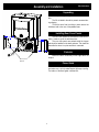
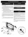
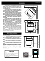
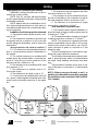
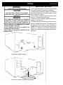
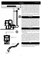
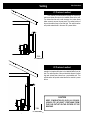
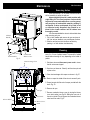
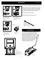
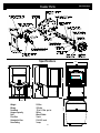
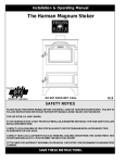
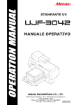
Installation & Operating Manual
The Harman PP38+ Pellet Stove
“Ce manuel est disponible en Français sur demande”
Tested by Intertek Testing Service
Tested to: UL 1482, ASTM E 1509-95,
Oregon 814-23-900 THRU 814-23-909,
ULC-S627-M90, WH-PN 025
R8
SAFETY NOTICE
PLEASE READ THIS ENTIRE MANUAL BEFORE YOU INSTALL AND USE YOUR NEW ROOM HEATER. FAILURE TO
FOLLOW INSTRUCTIONS MAY RESULT IN PROPERTY DAMAGE, BODILY INJURY, OR EVEN DEATH.
FOR USE IN THE U.S. AND CANADA. SUITABLE FOR INSTALLATION IN MOBILE HOMES
IF THIS HARMAN PELLET STOVE IS NOT PROPERLY INSTALLED, A HOUSEFIRE MAY RESULT. FOR YOUR SAFETY,
FOLLOW INSTALLATION DIRECTIONS.
CONTACT LOCAL BUILDING OR FIRE OFFICIALS ABOUT RESTRICTIONSAND INSTALLATION INSPECTION
REQUIREMENTS IN YOUR AREA.
CONTACT YOUR LOCAL AUTHORITY (SUCH AS MUNICIPAL BUILDING DEPARTMENT, FIRE DEPARTMENT, FIRE
PREVENTION BUREAU, ETC.) TO DETERMINE THE NEED FOR A PERMIT.
CETTE GUIDE D'UTILISATION EST DISPONIBLE EN FRANCAIS. CHEZ VOTRE CONCESSIONNAIRE DE HARMAN STOVE
COMPANY.
SAVE THESE INSTRUCTIONS.
Contents
P38+ Pellet Stove
Assembly & Installation
4
Venting
8
Turbo Control
12
Operation
13
Maintenance
14
Trouble Shooting
16
Feeder Parts
17
Specifications
17
Wiring Diagram
18
Options
19
Warranty
22
Please read this entire manual before you install and use your new
room heater. Failure to follow instructions may result in
property damage, bodily injury, or even death.
SUITABLE FOR MOBILE HOME INSTALLATIONS.
SAVE THESE INSTRUCTIONS
Harman Stove Company
352 Mountain House Road
Halifax, PA 17032
3
Assembly and Installation
P38+ Pellet Stove
Unpacking
Cut straps holding box together and remove box from
skid.
The 38+ is bolted to the skid to prevent movement during shipping.
To free the stove from the skid you must remove the
hold-down bolts in the rear of the pedestal base.
Installing Rear Cover Panels
The rear cover panels are removed from the stove to
make it easier to get at the hold-down bolts.
The rear cover panels are packed inside the hopper
and should be installed on the stove as shown. This should be
done after the stove is in place and flue is connected.
Firebrick
Install the firebrick horizontally on the angle above the
burnpot.
Rear Cover
Panels
Flame Guide
Install the cast iron flame guide on top of the burnpot
and make sure it is fully seated against the auger opening.
The bottom of the flame guide is marked 38+.
4
Door Assembly/Installation Tips
P38+ Pellet Stove
Assembling the door
Door Glass
Referring to the diagram, note how the various components of the door system fit together. Lay the load door face
down on a soft surface.
Clean the glass and gold door using a nonabrasive
cleaner. Install the glass gasket around the outer edge of the
front face of the door glass carefully to insure proper sealing.
Set the glass pane gently onto the door. Install the hold-down
clips and tighten with bolts as shown.
Install door on stove with hinge pins.
Install door handle as shown on the diagram. NOTE:
With the flat surface of the paw bolt to the inside of the door.
Turn the paw bolt "in" for approx. (17) turns.
Turn the brass elbow onto the paw bolt approx. (5) turns.
Align the set screw with the flat spot on the paw and
tighten.
After attaching the door handle, close and latch the door
by turning the handle to the six o'clock position. Does the door
rope compress? If not, loosen the set screw, turn the paw bolt
one more turn into the door. Repeat as required to achieve a
tight door fit.
* Rope the glass carefully to insure proper sealing.
* Apply the rope exactly along the edge of the external face of
the glass, not overhanging or pressed too far in from the edge.
* Make sharp 90o turns at the corners.
* Overlap the ends of the rope at the upper left or right corners.
Glass Retainer Clips
* Use the glass retainer clips and screws supplied in the door
kit.
* Use a 1/8" Allen wrench to tighten the glass clips to cast door
with 10-24 x 3/8" screws supplied.
Paw Bolt
* The paw bolt should be turned into the door from the inside
approximately 17 turns.
* With the set screw removed, turn the brass elbow onto the
paw bolt approximately 5 turns, or until a 1/16" clearance is
achieved between the elbow and the door face (make sure to
stop on the flat spot of the paw bolt).
* The set screw on the brass elbow must be aligned to contact
the flat spot on the paw bolt, then tighten using a 5/32" Allen
NOTE: Remember to thoroughly clean the glass and wrench.
the gold door frame before lighting the stove for the first time. * After attaching the door handle, close and latch the door by
turning the handle to the six o'clock position. During this
process observe to see that the door rope is being compressed
properly.
* If it does not compress, loosen the set screw and turn the
paw bolt one additional turn into the door. Repeat as required
to insure a tight seal.
HINGE PINS
DOOR
BRASS HANDLE
GLASS
PAW BOLT
HANDLE
BOLT
GLASS GASKET
4 GLASS
RETAINER
CLIPS
SET SCREW
WOOD HANDLE
4 GLASS
RETAINER
BOLTS
5
Installation
2"
2"
FL
O
O
R
PR
OT
E
C
TO
R
Fig. 3
2"
1"
6"
6"
10"
With Side Shields
Place the stove on a noncombustible floor protector that
extends 6 inches to the front, 6 inches to the sides and 1 inch
to the rear of the stove. The minimum floor protector material
is 24 gauge sheet metal.
Place the stove away from combustible walls at least as
far as shown in figures 3,4 and 5. Please note the difference in
side wall clearance with and without side shields.
Note that the clearances shown are minimum for safety
but do not leave much room for access when cleaning or
servicing. Please take this into account when placing the stove.
Connect the power cord to a 120 V.A.C. 60Hz grounded
receptacle. (A surge protector is recommened to protect the
circuit board).
Prior to installing flue pipe, connect a draft meter to the
stove as shown in fig. 6 . (The draft meter must have a minimum range of 0-.5). Set control board to "1" on the feed rate
dial. Record draft reading here _______ (should read at least
.15" cold. Allow combustion blower to operate for approximately 1 minute before recording or adjusting low draft.). See
page 19 for low draft adjustment procedures.
After connecting the flue system, follow the above procedure. However, prior to taking the draft reading be sure all
doors and windows in the home are closed. Record the draft
reading_______. If this reading is more than .05" lower than
the unconnected reading, check for possible restrictions or
the need for outside air (see page 7).
P38+ Pellet Stove
6"
FLOO R PROTECTOR
Mobile Home Installation
When installing this unit in a mobile home several requirements must be followed:
1. The unit must be bolted to the floor. This can be done
with 1/4" lag screws through the 2 holes in the base plate.
2. The unit must also be connected for the outside air. See
page 8.
3. Floor protection and clearances must be followed as
shown.
4. Unit must be grounded to the metal frame of the mobile
home.
CAUTION: This appliance must be vented to the outside.
Mobile home installation should be done in accordance
with the Manufactured Home and Safety Standard (HUD),
CFR 3280, Part 24.
16"
FLOOR PROTECTOR
Fig. 5
CAUTION
The stove is hot while in operation.
Keep children, clothing and
furniture away. Contact may cause
skin burns.
6
Fig. 6
Without Side Shields
Fig. 4
Venting
Requirements for Terminating the Venting
WARNING: Venting terminals must not be recessed into a wall or siding.
NOTE: Only PL vent pipe wall pass-throughs
and fire stops should be used when venting through
combustible materials.
NOTE: Always take into consideration the effect the prevailing wind direction or other wind currents will cause with flyash and /or smoke when placing the termination.
In addition, the following must be observed:
A. The clearance above grade must be a minimum of 18".1
B. The clearance to a window or door that may
be opened must be a minimum of 48" to the side
and 48" below the window/door, and 18" above the
window/door.1
(above window/door with outside air installed, 9”)
C. A 12" clearance to a permanently closed window is recommended to prevent condensation on
the window.
D. The vertical clearance to a ventilated soffit
located above the terminal within a horizontal distance of 2 feet (60 cm) from the center-line of the
terminal must be a minimum of 18".
E. The clearance to an unventilated soffit must
be a minimum of 12".
F. The clearance to an outside corner is 11"
from center of pipe.
G. The clearance to an inside corner is 12".
H. A vent must not be installed within 3 feet (90
cm) above a meter/regulator assembly when measured from the horizontal center-line of the regulator.1
P38+ Pellet Stove
I. The clearance to service regulator vent outlet
must be a minimum of 6 feet.1
J. The clearance to a non-mechanical air supply inlet to the building or the combustion air inlet to
any other appliance must be a minimum of 48”.1
K. The clearance to a mechanical air supply
inlet must be a minimum of 10 feet.1
(with outside air installed, 6 feet )
L. The clearance above a paved sidewalk or a
paved driveway located on public property must be
a minimum of 7 feet.1,2
M. The clearance under a veranda, porch, deck
or balcony must be a minimum of 12 inches.1,3
NOTE: The clearance to vegetation and other
exterior combustibles such as mulch is 36” as measured from the center of the outlet or cap. This 36”
radius continues to grade or a minimum of 7 feet
below the outlet.
1
Certain Canadian and or Local codes or regulations may require different clearances.
2
A vent shall not terminate directly above a sidewalk or paved driveway which is located between
two single family dwellings and serves both dwellings.
3
Only permitted if veranda, porch, deck, or balcony is fully open on a minimum of 2 sides beneath
the floor.
NOT E: Where passage t hrough a w all, or
partition of combustible construction is desired,
the installation shall conform to CAN/CSA-B365.
(if in Canada)
Inside Corner
Detail
Fixed
Closed
Fixed
Closed
Openable
Openable
V
= Vent terminal
A
= Air supply inlet
= Area where terminal is not permitted
7
Venting
P38+ Pellet Stove
IMPORTANT NOTICES
WARNING
• Due to high temperatures, the stove should be placed
out of traffic and away from furniture and draperies.
CAUTION
• Children and adults should be alerted to the hazards of
THE STRUCTURAL INTEGRITY OF THE MOBILE
high surface temperatures and should stay away to avoid
HOME FLOOR, WALL, AND CEILING/ROOF MUST BE burn to skin and/or clothing.
MAINTAINED.
• Young children should be carefully supervised when
they are in the same room as the stove.
WARNING
• Clothing and other flammable materials should not be
KEEP COMBUSTIBLE MATERIALS SUCH AS GRASS,
placed on or near this unit.
LEAVES, ETC. AT LEAST 3 FEET AWAY FROM THE
• Installation and repair of this Harman Stove should be
POINT DIRECTLY UNDER THE VENT TERMINATION.
done by a qualified service person. The appliance should
DO NOT INSTALL A FLUE DAMPER IN THE EXHAUST be inspected before use and at least annually by a
VENTING SYSTEM OF THIS UNIT.
qualified service person. More frequent cleaning will be
DO NOT CONNECT THIS UNIT TO A CHIMNEY FLUE required. It is imperative that control compartments,
SERVING ANOTHER APPLIANCE.
burners, and circulating air passageways of the stove be
INSTALL VENT AT CLEARANCES SPECIFIED BY THE
kept clean.
MANUFACTURER.
DO NOT INSTALL IN SLEEPING ROOM
3'
8
Venting
P38+ Pellet Stove
A combustion blower is used to extract the combustion
gases from the firebox. This causes a negative pressure in the
firebox and a positive pressure in the venting system as shown
in fig. 7. The longer the vent pipe and more elbows used in the
system, the greater the flow resistance. Because of these facts
we recommend using as few elbows as possible and 15 feet
or less of vent pipe. The maximum horizontal run should not
exceed 48". If more than 15 feet of pipe is needed, the diameter should be increased from 3" to 4" because a larger pipe
causes less flow resistance. Be sure to use approved pellet
vent pipe and wall pass through fittings.
IMPORTANT NOTICE
Pellet Vent Pipe or PL Vent Pipe Must be used.
Vent Pipe
Pellet venting pipe ( also known as PL vent ) is constructed of two layers with air space between the layers. This
air space acts as an insulator and reduces the outside surface temperature to allow a clearance to combustibles of only
3 inches. The sections of pipe lock together to form an air tight
seal in most cases; however, in some cases a perfect seal is
not achieved. For this reason and the fact that the 38+ operates with a positive vent pressure we specify that the joints
also be sealed with clear silicone.
Outside Air
Outside air is optional except in mobile homes and
where building codes require. The benefit of outside air is
increased efficiency and should be used in small, or very well
insulated homes.
To install outside air use 2 3/8" I.D. flex pipe part number
2-00-08543. There is a break-away hole on the rear panel
which must be removed before connecting the flex pipe. The
pipe should be run outside and terminate to the side or below
the vent pipe outlet so the flue outlet is more than 12" from the
inlet cover. The maximum length run of this pipe is 15 feet. If a
longer run is needed the size must be increased to 3". Inlet
cover part number 1-10-08542 should be used to keep bird,
rodents etc. out of the pipe.
Fig. 7
+ = Positive static pressure
= Negative static pressure
Outside air flex pipe
goes here
HRV
Flex pipe part#
2-00-08543
When installing in a house with a Heat Reclaiming Ventilation System (HRV) be sure the system is balanced and is
not creating a negative pressure in the house.
Inlet Cover part#
1-10-08542
9
Venting
P38+ Pellet Stove
#1 Preferred method
This method provides excellent venting for normal operation and allows the stove to be installed closest to the wall.
Two inches from the wall is safe; however, four inches allows
better access to remove the rear panel. The vertical portion of
the vent should be three to five feet high. This vertical section
will provide natural draft in the event of a power failure.
Fig. 8
3 ft.
to combustibles
#2 Preferred method
This method also provides excellent venting for normal
operation but requires the stove to be installed farther from the
wall. The vertical portion of the vent should be three to five feet
high and at least three inches from a combustible wall. This
vertical section will provide natural draft in the event of a power
failure.
CAUTION
KEEP COMBUSTIBLES (SUCH AS GRASS,
LEAVES, ETC.) AT LEAST 3 FEET AWAY FROM
THE FLUE OUTLET ON THE OUTSIDE OF THE
BUILDING.
3 ft.
to combustibles
Fig. 9
10
Venting
P38+ Pellet Stove
#4 Installing into an existing chimney
( US only )
This method provides excellent venting for normal operation. This method also provides natural draft in the event of
a power failure. If the chimney condition is questionable you
may want to install a liner as in method #7.
Fig. 10
#5 Installing into an existing fireplace
chimney ( US only )
This method provides excellent venting for normal operation. This method also provides natural draft in the event of
a power failure.
The damper area must be sealed with a steel plate or
fiberglass. A cap should be installed on the chimney to keep
out rain. If the chimney condition is questionable you may
want to install a liner all the way to the top as in method #6.
Fig. 11
11
Venting
P38+ Pellet Stove
#6 Installing into an existing fireplace
chimney ( US and Canada )
This method provides excellent venting for normal operation. This method also provides natural draft in the event of
a power failure.
In Canada and some places in the US it is required that
the vent pipe extend all the way to the top of the chimney.
In this method a cap should also be installed on the
chimney to keep out rain. Be sure to use approved pellet vent
pipe fittings. Seal pipe joints with silicone in addition to the
sealing system used by the manufacturer. Pipe size should be
increased to 4" using this method.
Fig. 12
#7 Installing into an existing chimney
( US and Canada )
This method provides excellent venting for normal operation. This method also provides natural draft in the event of
a power failure.
In Canada and some places in the US it is required that
the vent pipe extend all the way to the top of the chimney. The
pipe or liner inside the chimney should be 4"diameter.
In this method a cap should also be installed on the
chimney to keep out rain. One disadvantage of this method is
that it is harder to clean the vent pipe, therefore, there is a
tendancy not to do it as often as needed.
Fig. 13
12
Turbo Control
P38+ Pellet Stove
Feed Rate
When the Feed Rate is set to "1" and the
Blower is set to the lowest setting, only 75
watts of electricity are used.
Turning the knob passed the "OFF" position starts the
combustion blower and makes the stove ready to light as shown
in fig 14. The distribution blower and feed motor will also run
for one minute or less just to let you know they are operational.
After lighting the fire, the ESP probe in the exhaust senses
when the temperature is high enough to start the feed motor
and distribution blower.
The feed motor will start and stop as needed to maintain a fire relative to the dial setting of the feed rate.
Turbo Range
Turning the feed rate knob into the Turbo Range causes
the feed rate to increase, providing extra heat not available in
the normal range. It also causes the distribution blower to go
to full speed. This is because you are asking for extra heat
output, therefore, full blower speed is required.
Fig. 14
Blower Speed Adjustment
This knob adjusts the blower speed from "Low" to "Hi"
as desired. When the feed rate is turned into the Turbo Range,
the blower automatically goes to high to force maximum heat
into the room. The blower speed cannot be varied when in
Turbo Range.
When a thermostat is connected, the blower is controlled by heating demands.
Thermostat ( optional )
When a thermostat is connected to the stove it controls
the heat output. When the thermostat calls for heat, the feed
rate and blower go to "max" just like in Turbo Range. When
the thermostat is satisfied, the feed rate and blower speed
drop to the level set on the dials.
OFF
When the Feed Rate dial is turned to the OFF position
the fire will slowly die and go out. When the stove cools down
enough, all motors will stop.
If the stove runs out of pellets and cools down, the
control will shut down all but the combustion blower.
The control must be turned to OFF to stop the combustion blower. Whenever the stove runs out of pellets, the control must be turned to OFF and then back to the desired setting to reset the control for start-up.
Test Mode
To use test mode, turn the feed rate to OFF and then to
Turbo. This will cause all the motors to run for one minute or
less in order to verify operation. If the test does not last long
enough, simply recycle test mode.
Start
Position
13
Operation
P38+ Pellet Stove
Starting First Fire
Be sure the power cord is plugged into a 120 volt grounded
receptacle.
Placing too many pellets in
the burn pot may cause
the fire to be pushed off
the end.
Fill the hopper with pellets.
Fill the burn pot with pellets to a level no more than
shown in Fig. 14.
Turn Feed Rate Dial to "1". NOTE: Every time the control
is turned from "OFF" to any other position on the dial the
stove goes through a self test for a minute or less during
which all motors will run. After this period, only the
combustion motor run. See Test Mode.
Apply starting gel to pellets in burn pot and light the gel
as shown in fig. 15. Close the door after lighting (A low
draft pressure switch will not allow the feed motor
to operate with the door open). As the temperature of
Fig. 15
the fire increases, the feed motor will start and pellets will
feed into the burn pot. As the stove temperature inNever use gasoline, gasoline-type lantern fuel,
creases the distribution blower will start and run at the
kerosene, charcoal lighter fluid, or similar liquids to
speed set on the Blower Speed dial.
start or “freshen up” a fire in this heater. Keep all such
Normal Operation: After the fire is established turn the
liquids well away from the heater while it is in use.
feed rate to the desired setting from "1" to "5". The ESP
probe in the exhaust will sense the flue gas temperatures
and adjust the feed rate in order to maintain a stove
temperature relative to the setting on the dial. The blower
Speed may be adjusted by turning the blower to the
desired setting.
Turbo Operation: Turning the feed rate into the Turbo
range will provide approximately 5000 btu's more than in
Normal range.
When filling hopper be sure to remove any
pellets from ledge and around hinges before
Shut-Down Procedure
1"
closing lid.
To kill the fire or stop burning the stove, turn the Mode
Selector to "OFF". This will cause the fire to diminish
and burn out. When the fire burns out and the stove cools
down, everything will stop.
If you pull the plug to shut down the stove, all motors will
stop. This may cause incomplete combustion and
smoke in the firebox. If the load door is opened the
smoke may escape.
The best way to shut down the stove is simply let it run out of
pellets, then turn the control to "OFF".
Fig. 16
14
Maintenance
P38+ Pellet Stove
Removing Ashes
When approximatly 1 ton of pellets has been burned it
will be necessary to empty the ash pan.
Ashes should be placed in a metal container with
a tight fitting lid. The closed container of ashes should
be placed on a noncombustible floor or on the ground,
well away from all combustible materials, pending final disposal. If ashes are disposed of by burial in soil
or otherwise locally dispersed, they should be retained in the closed container until all cinders have
thoroughly cooled.
It is recommended that the stove is cold and shut down
when removing ash pan.
1. Pull on latch handles and remove ash pan as shown at
left. Use ash pan handle to carry and dispose of ashes.
2. Slide the ash pan back into the stove and latch by
pushing in on both latches simultaneously.
AshPan
Handle
Cleaning
Latch Handles
The stove will need to be cleaned for approximately
every 2 to 5 tons of pellets burned. The amount of pellets
burned before cleaning will vary depending on the brand of
pellets.
Combustion
Blower Cover
Fig. 17
Heat Exchanger Fins
1. Shut down stove and disconnect power cord to insure
that all motors are stopped.
2. Open burn pot clean-out. Clean fly ash from burn pot and
replace cover.
3. Clean heat exchanger with scraper as shown in fig 27.
4. Brush or scrape the inside of the stove to remove fly ash.
5. Scrape burnpot with flat end of scraper provided with the
stove. Fig. 33.
Scraper
Flue Outlet
Blower Wheel
Blower Cover
Latch
Fig. 18
15
6. Remove ash pan.
7. Remove combustion blower cover by turning the blower
cover latch vertical, see Fig.26. Sliding the cover out of
the slot on the left.This will expose the combustion blower
wheel and flue outlet, Fig.27.
Maintenance
P38+ Pellet Stove
8. Clean the blower wheel with a brush and a vacuum cleaner.
9. Use a brush to clean the flue, being careful not to damage
the ESP probe, see Fig. 30. The flue goes straight through
into the vent pipe (Fig.27) therefore, the vent pipe can also
be cleaned to some extent through the flue outlet.
10. Reinstall blower cover and relatch.
11.Slide ash pan into stove and latch into place.
Fig. 19
Latch "closed "with
blower cover in place.
Burn pot clean-out is
closed.
Fig. 20
Latch "open "with
blower cover partly
removed. Burn pot cleanout is open.
Brush not
supplied. Can be
found in hardware
stores.
Fig. 23
ESP probe
Soot and Fly Ash
Fig. 21
Exposed blower wheel
and flue opening,
NOTE: ESP probe is
visible.
The products of combustion will contain small particles of fly ash. The fly ash will collect in the exhaust venting system and restrict the flow of the
flue gases. Incomplete combustion, such as occurs during startup, shutdown, or incorrect operation of the room heater, will lead to some
soot formation which will collect in the exhaust
venting system. The exhaust venting system
should be inspected at least once every year
to determine if cleaning is necessary.
Blower cover
removed.
ESP Probe
Fig. 22
Be careful not to
damage ESP probe
when cleaning with
brush.
16
Fig. 24
Trouble Shooting
P38+ Pellet Stove
FEEDER DOES NOT FEED
SMOKE SMELL
1. No pellets in hopper.
Seal the vent pipe joints and connection to stove
2. Feed motor will not run until ESP
with silicone.
senses 165 deg. F. Maybe you did not put
FIRE HAS GONE OUT
enough pellets in the burn pot before lighting the
1. No pellets in hopper.
fire.
2. Feed rate too low.
3. Feed motor has failed.
3. Something is restricting fuel flow.
4. Something is restricting flow in the hopper or
4. Feed motor or draft motor has failed.
causing the slide plate to stick.
5. Power failure or blown fuse.
5. Firebox draft may be too low for low draft pressure switch in feeder circuit to operate. Check for SMOKE IS VISIBLE COMING OUT OF VENT
closed doors, loose or missing gasket on doors
1. Air-fuel ratio is too rich.
or hopper lid, faulty pressure switch.
A. Feed rate too high.
B. Draft too low caused by a gasket leak.
PARTIALLY BURNED PELLETS
1. Feed rate too high.
LOW HEAT OUTPUT
2. Draft too low. (Check burn pot clean- out slide
1. Feed rate too low
and door gasket).
2. Draft too low because of gasket leak.
3. Burn pot or heat exchanger tubes may need to
3. Poor quality or damp pellets
be cleaned.
4. Combination of 1. and 2.
4. Combination of all the above.
Helpful Hints
Cleaning Burn Pot
Whenever your stove is not burning, take the opportunity to scrape the burn pot to remove carbon buildup.
A vacuum cleaner is handy to remove the residue. Be
sure the stove is cold if you use a vacuum.
Carbon buildup can be scraped loose with the fire
burning using the special tool provided with your stove.
Scrape the floor and sides of the burn pot. The carbon
will be pushed out by the incoming fuel. Always wear
gloves to do this.
Removing Ashes
Turn the Feed Rate Dial to number 1 approximately
30 minutes before removing ashes. This will result in a
cooler stove and ash pan.
Maximum Turbo settings are not needed in most
cases. Operating in the normal range is recommended
when maximum heat output is not required. The ESP
probe prevents the stove from being over-fired.
Keep the stove free of dust and dirt.
Fuel
Pellet fuels are put into 3 categories in terms of
ash content. Premium at 1% or less, Standard at 3% or
less and all others at 3% or more.
The 38+ is capable of burning all 3 categories of
pellets due to a patented feeder and burn pot system.
It should be noted, however, that higher ash con17
tent will require more frequent ash removal and may
provide less BTU's per lb. Normally, standard and high
ash pellets cost less than premium pellets and can be
cost effective when burned in the 38+.
The moisture content must not exceed 8%. Higher
moisture will rob BTU's and may not burn properly.
Feeder Parts
P38+ Pellet Stove
Specifications
29.375"
32"
12.375"
22"
9"
Weight
Blower
Feed Rate
Hopper Capacity
Fuel
Flue Size
Outside Air Size
Fuse Rating
212 lbs.
135 cfm
.75 to 5.5 lbs. per hr.
50 lbs.
Wood Pellets
3 inch
2 3/8 I.D. inch
3 amp
18
28.5"
5.250"
Wiring Diagram
5
19
P38+ Pellet Stove
Thermostat (optional)
P38+ Pellet Stove
What is a thermostat?
A thermostat is a switch that opens or closes at a
set room temperature. For example: When you set the
thermostat to 70 degrees, the switch will be closed causing the stove to burn on "Turbo" until the room temperature reaches 70 degrees. Then the switch will open, causing the stove to go to "low" which is where the feed rate
is set.
Installing Thermostat
The thermostat should be mounted in a central location. Avoid isolated rooms with poor air circulation.
Run thermostat wire ( available at most hardware
stores) from the thermostat to the rear of the unit and up
to the thermostat terminals on the control board. disconnect power before accessing control board. The control board can be tilted out at the top to allow access to
the thermostat terminals on the control board. Use the
two female spade terminals (supplied) to make the connection.
Thermostat Terminals
Low Draft Adjustment ( cold stove only )
This adjustment should only be made by an authorized Harman dealer using a draft meter to check results.
The Low Draft Adjustment is set at the factory in the minimum position. This setting should give the proper draft
with 118 V.A.C. 60 Hz or higher.
To check the low draft, turn the feed rate dial to "1"
and allow one minute before taking a draft reading. If the
draft is too low (below .15), Disconnect the power and
turn the trim pot on back of the control board clockwise
slightly to increase draft. Reconnect power and wait one
minute before rechecking draft. Repeat until .15 to .18
draft reading is reached.
Trim Pot
Warning
Always disconnect power
before touching control board
20
Door Options
P38+ Pellet Stove
Tabs
Tabs
"Sunrise" Gold Trim
Gold Door
This kit includes a gold trim piece for the ash lip and a
gold Sunrise piece for the door.
Referring to the diagram, page 4, note how the various
components of the door system fit together. Lay the load door
face down on a soft surface.
Clean the glass thoroughly using a nonabrasive glass
cleaner. Install the glass gasket around the outer edge of the
front face of the door glass carefully to insure proper sealing.
Note: There are 4 tabs on the Sunrise. These tabs have
a step on the front side and are flush on the back side. Place
the "Sunrise" in the door so the step side is to the front.
Set the glass pane gently onto the door. Install the holddown clips and tighten with bolts as shown on page 5.
To install ash lip trim, simply slide the trim over the ash
lip and into the groove on the trim.
The gold door is assembled and installed the same as
the standard door. Refer to page 4. Be careful not to scratch
the glass and be sure to clean the gold before starting a fire in
the stove.
To install ash lip trim, simply slide the trim over the ash
lip and into the groove on the trim.
21
Cleaning Gold
The gold plated door and gold Sunrise should never be
buffed or polished.Abrasive clesners and metal polishes will
remove the plating and therefore should never be used. If the
gold needs to be cleaned, wait until the stove is completely
cool, then use a sponge, soap and water to gently remove dirt
and stains. Before relighting the stove, remove all soap residue and wipe dry.
Options
P38+ Pellet Stove
Hopper Extension
Side Heat Shields
The hopper extension allows you to put more pellet
Side heat shields are available to reduce the
fuel in the hopper and extends burn time on one load of pellets.
clearance to combustible materials.
The hopper extension adds 50 pounds to the existing 50 pound
hopper capacity, allowing you to load 100 pounds of pellets at
one time.
22
Warranty
P38+ Pellet Stove
HARMAN GOLD WARRANTY
6 YEAR TRANSFERABLE LIMITED
WARRANTY (Resi denti al)
1 YEAR LIMITEDWARRANTY (Commercial)
Harman Stove Company warrants its products to be free from defects in material or workmanship, in normal use and
service, for a period of 6 years from the date of sales invoice and for mechanical and electrical failures, in normal use and
service, for a period of 3 years from the date of sales invoice.
If defective in material or workmanship, during the warranty period, Harman Stove Company will, at its option, repair or
replace the product as described below.
The warranty above constitutes the entire warranty with respect to Harman Stove Company products. HARMAN STOVE
COMPANY MAKES NO OTHER WARRANTY, EXPRESSED OR IMPLI ED, INCLUDING “ ANY” WARRANTY OF
MERCHANTABILITY, OR WARRANTY OF FITNESS FOR A PARTICULAR PURPOSE. No employee, agent, dealer, or
other person is authorized to give any warranty on behalf of Harman Stove Company. This warranty does not apply if the product
has been altered in any way after leaving the factory. Harman Stove Company and its agents assume no liability for “ resultant
damages of any kind” arising from the use of its products. In addition, the manufacturer and its warranty administrator shall be
held free and harmless from liability from damage to property related to the operation, proper or improper, of the equipment.
THERE ARE NO WARRANTIES WHICH EXTEND BEYOND THE DESCRIPTION ON THE FACE HEREOF.
THESE WARRANTIES APPLY only if the device is installed and operated as recommended in the user’s manual.
THESE WARRANTIES WILL NOT APPLY if abuse, accident, improper installation, negligence, or use beyond rated
capacity causes damage.
HOW TO MAKE A CLAIM - Any claim under this warranty should be made to the dealer from whom this appliance was
purchased. Then contact is made with manufacturer, giving the model and serial numbers, the date of purchase, your dealer’s
name and address, plus a simple explanation of the nature of the defect. Extra costs such as mileage and overtime are not
covered. Nuisance calls are not covered by these warranties.
THIS WARRANTY IS LIMITED TO DEFECTIVE PARTS - REPAIR AND/OR REPLACEMENT AT HARMAN
STOVE COMPANY’S OPTION AND EXCLUDES ANY INCIDENTAL AND CONSEQUENTIAL DAMAGES CONNECTED
THEREWI TH.
WARRANTY EXCLUSIONS: Failure due, but not limited to, fire, lightning, acts of God, power failures and/or surges, rust,
corrosion and venting problems are not covered. Damage and/or repairs including but not limited to; remote controls, filters,
fuses, knobs, glass, ceramic brick panels, ceramic fiber afterburners, door packing, tile, ceramic log sets, paint, batteries or
battery back-up and related duct work are not covered. Also excluded from this warranty are consumable or normal wear items
including but not limited to; flame guides, grates, coal bars, afterburner hoods, fire brick, gaskets. Additional exclusions for corn
stoves are burnpot housing weldment, burnpot grate weldment (pellet or corn), burnpot front plate (pellet or corn), burnpot front
plate lock, corn auger extension, ceramic insert, and ceramic insert plate. Additional or unusual utility bills incurred due to any
malfunction or defect in equipment and the labor cost of gaining access to or removal of a unit that requires special tools or
equipment are not covered. Maintenance needed to keep the stove in “ good operating condition” is not covered. This
includes, but is not limited to, cleaning, adjustment of customer controls and customer education. Labor, materials, expenses
and/or equipment needed to comply with law and/or regulations set forth by any governmental agencies are not covered.
This Warranty provides specific legal rights and the consumer may have other rights that vary from state to state.
In the event of change in ownership, the remaining portion of this warranty may be transferred to the new owner by
sending the new owner information and a transfer fee of $25.00 US to the Harman Stove Company.
PLEASE READ THE LITERATURE BY THE MANUFACTURER FOR THE VARIOUS ACCESSORY DEVICES. THE
MANUFACTU RER WARRANTS THESE ACCESSORY DEVICES, NOT HARMAN STOVE COMPANY OR THEIR
WARRANTY ADMINISTRATOR. FURTHERMORE, THESE ACCESSORY DEVICES MUST BE INSTALLED AND USED
ACCORDING TO THE RECOMMENDATIONS OF THE MANUFACTURER.
REMEDIES - The remedies set forth herein are exclusive and the liability of seller with respect to any contract or sale or
anything done in connection therewith, whether in Contract, in tort, under any warranty, or otherwise, shall not, except as herein
expressly provided, exceed the price of the equipment or part of which such liability is based.
CLARIFY - The above represents the complete warranty, which is given in connection with stoves, manufactured by
Harman Stove Company. No other commitments, verbal or otherwise, shall apply except by a written addendum to this
warranty.