1
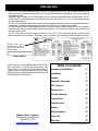
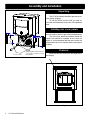
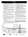
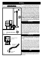
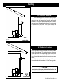
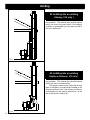
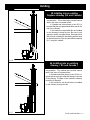
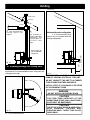
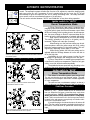
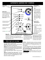
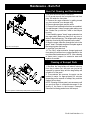
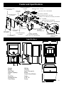
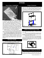
Installation & Operating Manual
The Harman PC 45 Corn/Pellet Stove
“Ce manuel est disponible en Français sur demande”
R3
SAFETY NOTICE
PLEASE READ THIS ENTIRE MANUAL BEFORE YOU INSTALL AND USE YOUR NEW ROOM HEATER. FAILURE TO
FOLLOW INSTRUCTIONS MAY RESULT IN PROPERTY DAMAGE, BODILY INJURY, OR EVEN DEATH.
FOR USE IN THE U.S. AND CANADA. SUITABLE FOR INSTALLATION IN MOBILE HOMES
IF THIS HARMAN STOVE IS NOT PROPERLY INSTALLED, A HOUSE FIRE MAY RESULT. FOR YOUR SAFETY, FOLLOW
INSTALLATION DIRECTIONS.
CONTACT LOCAL BUILDING OR FIRE OFFICIALS ABOUT RESTRICTIONS AND INSTALLATION INSPECTION
REQUIREMENTS IN YOUR AREA.
CONTACT YOUR LOCAL AUTHORITY (SUCH AS MUNICIPAL BUILDING DEPARTMENT, FIRE DEPARTMENT, FIRE
PREVENTION BUREAU, ETC.) TO DETERMINE THE NEED FOR A PERMIT.
CETTE GUIDE D'UTILISATION EST DISPONIBLE EN FRANCAIS. CHEZ VOTRE CONCESSIONNAIRE DE HARMAN STOVE
COMPANY.
SAVE THESE INSTRUCTIONS.
R1
2
PC 45 Corn/Pellet Stove
Introduction
The PC 45 Corn Stove makes burning corn more convenient than ever. It’s special Sidewinder Burn Pot
allows corn to be burned from three days up to a week without cleaning, depending on the corn’s moisture
level and burn rate.
Automatic Ignition allows you to fill the hopper, set your desired room temperature and walk away. The PC
45 will adjust it’s feed rate based on the temperatures received by the room sensor, and keep your home
at the set temperature.
The PC 45’s automatic temperature control system eliminates the warm/cold cycle associated with thermostatically controlled heating systems and even turns the PC 45 on and off as needed.
Our exclusive Accordion Heat Exchanger and Air Cooled Combustion Blower allows the PC 45 to produce
maximum heat without creating high exhaust temperatures. The Outside Air option can increase heat
efficiency even more.
The PC 45 can burn corn with moisture levels up to 16%, with 14.5% or less being ideal. It can also burn
pellets regardless of ash content. This allows you to buy lower cost fuel and still achieve the same results.
Plea se c opy y o u r
serial number from the
label on your stove to
the box below.
SERIAL NUMBER
SAFETY NOTICE: IF THIS HARMAN STOVE IS NOT PROPERLY INSTALLED. A HOUSE FIRE MAY RESULT. FOR
YOUR SAFETY, FOLLOW THE INSTALLATION DIRECTIONS CONTACT LOCAL BUILDING OR FIRE OFFICIALS
ABOUT RESTRICTIONS AND INSTALLATION INSPECTION
REQUIREMENTS IN YOUR AREA.
Harman Stove Company
352 Mountain House Road
Halifax, PA 17032
[email protected]
Table of Contents
Assembly & Installation
4
Installation
6
Venting
7
Automatic Operation
13
ESP Control
17
Maintenance
19
Trouble Shooting
22
Feeder Parts
23
Specifications
23
Options
24
Wiring Diagram
26
Parts List
27
Warranty
28
PC 45 Corn/Pellet Stove 3
Assembly and Installation
Unpacking
The PC 45 is bolted to the skid to prevent movement during shipping.
To free the stove from the skid you must remove the hold-down bolts in the rear of the pedestal
base.
Installing rear cover panels
The rear cover panels are removed from the
stove to make it easier to get at the hold-down bolts.
The rear cover panels are packed inside the
hopper and should be installed on the stove as
shown. It is recommended that the rear covers are
installed after the unit is in place and the vent pipe is
installed.
Shipping Bolts: These holes are
also used for Mobile Home
Installation
Rear
Cover Panels
Firebrick
Install the firebrick vertically on the angle above
the burnpot.
Fig. 1
Fig. 2
4
PC 45 Corn/Pellet Stove
Door Assembly/Installation Tips
Bottom Glass Retainer Clip Instructions
(2) Glass Retainer Clips
supplied with the door kit
Follow the instructions in the door kit except for the
bottom glass retainers. Install the special glass
retainer clips to the bottom of the door.
There is a left and right retainer clip with a radius to
match the door bottom. The fiber glass rope on the
clip must be facing the stove body when installed,
NOT FACING THE GLASS!!
(4) 10-24 x 3/8" button head allen
screws supplied in the door kit
These clips are designed to direct the air wash air
more evenly.
Gasket goes
toward the stove
(1) left hand
(2) glass retainer clips
(1) right hand
Fig. 3
Gasket
goes
toward
the stove
Assembling the door
DOOR
HINGE
PINS
GLASS
PAW
BOLT
GLASS
GASKET
4 GLASS
RETAINER
CLIPS
4 GLASS RETAINER
BOLTS
Fig. 4
BRASS
HANDLE
SET
SCREW
WOOD
HANDLE
HANDLE
BOLT
Fig. 5
• Referring to the diagram, note how the various
components of the door system fit together.
• Lay the load door face down on a soft surface.
• Clean the glass and gold door using a nonabrasive
cleaner. Install the glass gasket around the outer edge
of the front face of the door glass carefully to insure
proper sealing. Set the glass pane gently onto the
door. Install the hold-down clips and tighten with bolts
as shown.
• Install door on stove with hinge pins.
• Install door handle as shown on the diagram.
NOTE: With the flat surface of the paw bolt to the
inside of the door.
• Turn the paw bolt "in" for approx. (17) turns.
• Turn the brass elbow onto the paw bolt approx. (5)
turns.
• Align the set screw with the flat spot on the paw
and tighten.
• After attaching the door handle, close and latch
the door by turning the handle to the six o'clock
position. Does the door rope compress? If not,
loosen the set screw, turn the paw bolt one more
turn into the door. Repeat as required to achieve a
tight door fit.
NOTE: Remember to thoroughly clean the glass and
the gold door frame before lighting the stove for the
first time.
PC 45 Corn/Pellet Stove 5
Installation
Installing
9"-13"
FL
O
O
R
PR
OT
E
9"-13"
C
TO
R
9" With Side Shields
13" Without Side Shields
Fig. 6
2"
6"
6"
10"
Mobile Home Installation
When installing this unit in a mobile home several
requirements must be followed:
1. The unit must be bolted to the floor. This can be done
with 1/4" lag screws through the 2 holes in the base plate.
2. The unit must also be connected for the outside
air. See page 8.
3. Floor protection and clearances must be followed
as shown.
4. Unit must be grounded to the metal frame of the
mobile home.
CAUTION: This appliance must be vented to the outside.
Duetohightemperatures, thestoveshouldbeplacedout of traffic
andawayfromfurnitureanddraperies.
Children and adults should be alerted to the hazards of high surface temperatures and should stay away
to avoid burn to skin and/or clothing.
Young children should be carefully supervised when
they are in the same room as the stove.
Clothing and other flammable materials should not
be placed on or near this unit.
Installation and repair of this Harman Stove should
be done by a qualified service person. The appliance
should be inspected before use and at least annually by a
qualified service person. More frequent cleaning will be
required. It is imperative that control compartments, burners, and circulating air passageways of the stove be kept
clean.
Mobile home installation should be done in accordance
with the Manufactured Home and Safety Standard (HUD),
CFR 3280, Part 24.
6
PC 45 Corn/Pellet Stove
FLOOR PROTECTOR
With Side Shields
1"
6"
Fig. 7
18"
FLOOR PROTECTOR
Fig. 8
Fig. 9: Refer to page 18 for
detailed draft settings and
adjustment procedures.
Without Side Shields
Place the stove on a noncombustible floor protector that extends 6 inches to the front, 6 inches to the
sides and 1 inch to the rear of the stove. The minimum
floor protector material is 24 gauge sheet metal.
Place the stove away from combustible walls at least
as far as shown in figures 6,7 & 8. Please note the difference in side wall clearance with and without side shields.
Note that the clearances shown are minimum for
safety but do not leave much room for access when cleaning or servicing. Please take this into account when placing the stove.
Connect the power cord to a 120 V.A.C. 60Hz
grounded receptacle. (A surge protector is recommened
to protect the circuit board).
Prior to installing the flue pipe, connect a draft meter
to the stove as shown in fig. 9. (The draft meter must
have a minimum range of 0"- 0.5"). Turn stove to "TEST"
Mode and record the draft reading ______. After the flue
pipe is connected, check the draft reading again making
sure all doors and windows in the home are closed. If
this reading is more than.05" higher than the unconnected
reading, check for possible restrictions or the need for
outside air. (See page 8).
Venting
Requirements for Terminating the Venting
WARNING: Venting terminals must not be recessed into a wall or siding.
NOTE: Only PL vent pipe wall pass-throughs
and fire stops should be used when venting through
combustible materials.
NOTE: Always take into consideration the effect the prevailing wind direction or other wind currents will cause with flyash and /or smoke when placing the termination.
In addition, the following must be observed:
A. The clearance above grade must be a minimum of 18".1
B. The clearance to a window or door that may
be opened must be a minimum of 48" to the side,
48" below the window/door, and 12" above the window/door.1
( with outside air installed, 18” )
C. A 12" clearance to a permanently closed
window is recommended to prevent condensation
on the window.
D. The vertical clearance to a ventilated soffit
located above the terminal within a horizontal distance of 2 feet (60 cm) from the center-line of the
terminal must be a minimum of 18".
E. The clearance to an unventilated soffit must
be a minimum of 12".
F. The clearance to an outside corner is 11"
from center of pipe.
G. The clearance to an inside corner is 12".
H. A vent must not be installed within 3 feet (90
cm) above a gas meter/regulator assembly when
measured from the horizontal center-line of the regulator.1
I. The clearance to service regulator vent outlet
must be a minimum of 6 feet.1
J. The clearance to a non-mechanical air supply inlet to the building or the combustion air inlet to
any other appliance must be a minimum of 48”.1
K. The clearance to a mechanical air supply
inlet must be a minimum of 10 feet.1
(with outside air installed, 6 feet )
L. The clearance above a paved sidewalk or a
paved driveway located on public property must be
a minimum of 7 feet.1,2
M. The clearance under a veranda, porch, deck
or balcony must be a minimum of 12 inches.1,3
NOTE: The clearance to vegetation and other
exterior combustibles such as mulch is 36” as measured from the center of the outlet or cap. This 36”
radius continues to grade or a minimum of 7 feet
below the outlet.
1
Certain Canadian and or Local codes or regulations may require different clearances.
2
A vent shall not terminate directly above a sidewalk or paved driveway which is located between
two single family dwellings and serves both dwellings.
3
Only permitted if veranda, porch, deck, or balcony is fully open on a minimum of 2 sides beneath
the floor.
NOT E: Where passage t hrough a w all, or
partition of combustible construction is desired,
the installation shall conform to CAN/CSA-B365.
(if in Canada)
Inside Corner
Detail
Fixed
Closed
Openable
Fixed
Closed
Openable
V
= Vent terminal
A
= Air supply inlet
= Area where terminal is not permitted
PC 45 Corn/Pellet Stove 7
Venting
IMPORTANT NOTICE
Pellet Vent Pipe or PL Vent Pipe Must be used.
A combustion blower is used to extract the combustion gases from the firebox. This causes a negative pressure in the firebox and a positive pressure
in the venting system as shown in fig. 10. The longer
the vent pipe and more elbows used in the system,
the greater the flow resistance. Because of these
facts we recommend using as few elbows as possible and 15 feet or less of vent pipe. The maximum
horizontal run should not exceed 48". If more than
15 feet of pipe is needed, the diameter should be
increased from 3" to 4" because a larger pipe causes
less flow resistance. Be sure to use approved
pellet vent pipe wall and ceiling pass through
fittings to go through combustible walls and
ceilings. Be sure to use a starting collar to attach
the venting system to the stove. The starting collar must be sealed to the stove with high temp
silicone caulking.
Vent Pipe
Fig. 10
+ = Positive static pressure
= Negative static pressure
Pellet venting pipe ( also known as PL vent ) is
constructed of two layers with air space between
the layers. This air space acts as an insulator and
reduces the outside surface temperature to allow a
clearance to combustibles of only 3 inches. The
sections of pipe lock together to form an air tight
seal in most cases; however, in some cases a perfect seal is not achieved. For this reason and the
fact that the PC45 operates with a positive vent pressure we specify that the joints also be sealed
with clear silicone.
Outside Air
Outside air flex pipe
goes here
Flex pipe part#
2-00-08543
Outside air is optional except in mobile homes
and where building codes require. The benefit of
outside air is mainly noticed in small very tight
houses.
To install outside air use 2 3/8" I.D. flex pipe
part number 2-00-08543. There is a break-away hole
on the rear panel which must be removed before
connecting the flex pipe. The pipe should be run outside and terminate 3 feet or more to the side or below the vent pipe outlet. Never terminate the outside
air above the vent pipe outlet. The maximum length
run of this pipe is 15 feet. If a longer run is needed
the size must be increased to 3". Inlet cover part
number 1-10-08542 should be used to keep birds,
rodents etc.out of pipe.
HRV
Inlet Cover part#
1-10-08542
Fig. 11
8
PC 45 Corn/Pellet Stove
When installing in a house with a Heat Reclaiming Ventilation System (HRV) be sure the system is
balanced and is not creating a negative pressure in
the house.
Venting
#1 Preferred method
This method provides excellent venting for normal operation and allows the stove to be installed
closest to the wall. Two inches from the wall is safe;
however, four inches allows better access to remove
the rear panel. The vertical portion of the vent should
be three to five feet high. This vertical section will
provide natural draft in the event of a power failure.
3 ft.
Fig. 12
to
combustibles
#2 Preferred method
This method also provides excellent venting for
normal operation but requires the stove to be installed
farther from the wall. The vertical portion of the vent
should be three to five feet high and at least three
inches from a combustible wall. This vertical section will provide natural draft in the event of a power
failure.
If the stove is installed below grade the vent
termination should be at least 1 foot above grade.
CAUTION
Keep combustible materials (such as grass, leaves,
etc.) at least 3 feet away from the flue outlet on the
outside of the building.
3 ft.
Fig. 13
to
combustibles
PC 45 Corn/Pellet Stove 9
Venting
#3 Installing into an existing
chimney ( US only )
This method provides excellent venting for normal operation. This method also provides natural
draft in the event of a power failure. If the chimney
condition is questionable you may want to install a
liner as in method #6.
Fig. 14
#4 Installing into an existing
fireplace chimney ( US only )
This method provides excellent venting for normal operation. This method also provides natural
draft in the event of a power failure.
The damper area must be sealed with a steel
plate or fiberglass. A cap should be installed on the
chimney to keep out rain. If the chimney condition is
questionable you may want to install a liner all the
way to the top as in method #5.
Fig. 15
10
PC 45 Corn/Pellet Stove
Venting
#5 Installing into an existing
fireplace chimney (US and Canada)
This method provides excellent venting for normal operation. This method also provides natural
draft in the event of a power failure.
In Canada and some places in the US it is
required that the vent pipe extend all the way to the
top of the chimney.
In this method a cap should also be installed
on the chimney to keep out rain. Be sure to use
approved pellet vent pipe fittings. Seal pipe joints
with silicone in addition to the sealing system used
by the manufacturer. Pipe size should be increased
to 4" using this method.
Fig. 16
#6 Installing into an existing
chimney ( US and Canada )
This method provides excellent venting for normal operation. This method also provides natural
draft in the event of a power failure.
In Canada and some places in the US it is required that the vent pipe extend all the way to the top
of the chimney. The pipe or liner inside the chimney
should be 4"diameter.
In this method a cap should also be installed
on the chimney to keep out rain.
Fig. 17
PC 45 Corn/Pellet Stove 11
Venting
12" min.
Storm collar
Flashing
3" min.
3" min.
PL vent manufacturer's
fi re stop s pa ce r an d
support
3" min.
No insulation or
other combustible
ma te ri al s are
allowed within 3"
of the PL ve nt
pipe.
Minimum flue vent configuration
It is rec ommended that
outside air be installed with this
venting configuration.
12"
Fig. 18
#7 Installing through the ceiling vent
Thr ough the c eiling vent, f ollow PL vent
manufacturers recommendations when using wall and
ceiling pass through.
Min. above ground level
(See Page 6 for
corner installation
clearances)
Fig. 19
DO NOT INSTALL A FLUE DAMPER IN THE
EXHAUST VENTING SYSTEM OF THIS UNIT.
DO NOT CONNECT THIS UNIT TO A CHIMNEY
FLUE SERVING ANOTHER APPLIANCE.
INSTALL VENT AT CLEARANCES SPECIFIED
BY THE MANUFACTURER
WARNING
DO NOT INSTALL IN SLEEPING ROOM
CAUTION
THE STRU CTURAL INTEGRITY OF TH E
MOBILE HOME FLOOR, WALL, AND CEILING/
ROOF MUST BE MAINTAINED.
CAUTION
Fig. 20
12
PC 45 Corn/Pellet Stove
THE STOVE IS HOT WHILE IN OPERATION.
KEEP C HILD REN, C LOTH IN G AN D
FURNITURE AWAY. CONTACT MAY CAUSE
SKIN BURNS.
AUTOMATIC IGNITION/OPERATION
The PC45 corn/pellet stove is more than just automatic ignition, it is also automatic temperature
control. The automatic system will allow the fire size to be adjusted to match the heating needs
and even put the fire out if necessary. If heat is needed after the fire is out, the PC 45 will
automatically re-ignite and adjust the fire size to match the heating need. The totally automatic
room sensor mode is recommended because of its efficiency.
The unit can be switched between "AUTO" and "MANUAL" at any time during operation.
Igniter switch to "AUTO"
Room Temperature Mode
Fig. 21:Room Temperature M ode: This setting will produce
a room temperature of 70 degrees with the distribution blower
at medium speed.
Stove Temperature Mode
In "Room Temp Mode" heat output is controlled automatically by the Room Sensing Probe. When the Room Sensing Probe calls for heat, the stove will increase output. When
the Room Sensing Probe is getting close to the set temperature, the stove will begin to level off output and keep the fire
burning at just the right temperature to maintain that setting.
High output is determined by the feed rate setting.
This setting, generally on #2 (corn) or #4 (pellet), can be
increased if higher burn rates are necessary.
When burning corn the feed rate setting can be adjusted anywhere within the yellow range with a #3 setting
being the maximum setting, #1 the lowest setting. This setting will vary depending on the quality of corn used.
When burning pellets the feed rate setting can be
adjusted within the full range between #1 on the low side to
#6 on the high side.
Overfeeding is not a safety concern, but the fire may
be pushed off the burnpot and extinguish in the ash pan.
In "Room Temp Mode" a constant fuel consumption rate
is sacrificed for exact room temperature. Therefore, as it gets
colder more fuel will be burned automatically.
The distribution blower speed will vary according to the
position of the mode selector pointer, and fire size.
Igniter switch to "AUTO"
Stove Temperature Mode
This setting will produce medium heat with the
distribution blower on "low".
This allows for automatic ignition upon start-up only.
The unit can then be set at any desired setting. The heat
output and fuel consumption will remain constant regardless
of room temperature.
The unit's low burn or maintenance setting is as low as it
will go. It will not go out unless it runs out of fuel or is turned off.
Shut-Down Procedure
This setting will produce continuous maximum heat output
with the distribution blower at full speed.
Fig. 22
To kill the fire or stop burning the stove, turn the Mode
Selector to "OFF". This will cause the fire to diminish and
burn out. When the fire burns out and the stove cools down
everything will stop . NOTE : T he com bustion blower
motor will run for 5 hours after the stove is completely
cool. This insures that all fuel in the burnpot and ashes
located in the ash pan are completely cold before shut
down of the combustion motor.
If you pull the plug to shut down the stove, all motors will
stop. This may cause incomplete combustion and smoke in
the firebox. If the load door is opened the smoke may escape.
The best way to shut down the stove is simply let it run
out of fuel, then the stove will shut down automatically.
PC 45 Corn/Pellet Stove 13
AUTOMATIC START UP
Starting the Fire
Igniter Switch to"AUTO"(up position)
Make sure the unit is plugged into a 120 VAC, 60 HZ
electrical source. The power light should be the only
light lit. Anytime there is interruption in power at the
receptacle, the combustion blower will run for 1
minute after the power is regained.
1.Turn the Mode Selector to "OFF"
Fig. 23
2. Fill the hopper with corn or pellets.
3. Clean the burn pot and housing, if necessary.
4. If starting after an empty hopper, turn the feed
adjuster to "TEST" until the fuel is visible in the auger
tube opening. This also allows you to check the
motors for operation.
NOTE: The auger motor will not operate with the
view door or ash door open.
NOTE: The initial start-up on a new stove may require
the corn to be purged into the burnpot area before
continuing to step 5.
5. Turn the feed adjuster to #2 (corn) or #4 (pellet)
6. Flip the igniter switch up into the "AUTO" position.
7. Turn the temperature dial to the desired room
temperature.
8. Turn the mode selector dial to Room Temperature
or Stove Temperature.
9. Fill the hopper with corn or pellets and remove the
ashes as required.
Warning
"NEVER USE GASOLINE, GASOLINE-TYPE LANTERN
FUEL, KEROSENE, CHARCOAL LIGHTER FLUID, OR
SIMILAR LIQUIDS TO START OR "FRESHEN UP " A
FIRE IN THIS HEATER. KEEP ALL SUCH LIQUIDS
WELL AWAY FROM THE HEATER WHILE IN USE".
14
PC 45 Corn/Pellet Stove
MANUAL IGNITION/OPERATION
The PC45 Corn/Pellet Stove is capable of manual operation. This also allows the operator to manually control operation during an emergency (i.e. ignitor failure, when using a
502H battery backup, or when using certain generators.)
The unit can be switched between "AUTO" and "MANUAL" at any time during operation.
NOTE: When starting the unit in the "AUTO" mode and switching to "MANUAL",
the fire must be large enough to turn the ignitor light off (located on the control
board). This is a signal that the start cycle is completed and the fire will not go out.
Igniter Switch to "MANUAL"
Room Temperature Mode
Fig. 24: Room Temperature Mode: This setting will produce a
room temperature of 70 degrees with the distribution blower
at medium speed.
Manual Stove Temperature Mode
O
O
The fire will have to be lit with starting gel and a
match, or started automatically, see "Automatic Operation". Turn to "Manual" position when the fire is established.
The difference between "AUTO" Room Temperature Mode and "Manual" Room Temperature Mode is
that the fire will not go out as the room temperature
goes above the control board setting. The unit can only
go to low burn and will remain there until it runs out of
fuel or until more heat is needed and the feed rate increases. Feed rate adjustments and dial settings are
the same as "AUTO" settings.
Igniter Switch to "MANUAL"
Stove Temperature Mode
The advantage of this mode is to allow the operator to have a large viewing fire without blowing extra
heat into the room.
During operation, with the temperature dial set at
#5 or less, the distribution fan will not operate. A #5 on
the temperature dial and a #5 on the feed adjuster is
approximately 80% output. It is not necessary to operate the distribution blower below this point. Therefore,
there can be a higher feed rate ( a larger viewing fire)
without an excess of hot air blowing into the room.
An example of when to use the Manual Stove Temperature Mode is if you want to watch a large fire and
the room is already up to temperature. The Stove Temperature Mode allows you to have a larger fire and a
lower sound level, without the distribution blower.
NOTE: During the use of this mode, if you
keep increasing the temperature dial setting to increase the fire size, the distribution blower will automatically come on when the ESP Temperature
reaches 350o F, or 81% output.
Fig. 25: This setting will produce a large viewing fire without a
distribution blower operating.
PC 45 Corn/Pellet Stove 15
MANUAL START UP
Starting the Fire
Igniter Switch to"MANUAL" (down position)
Make sure the unit is plugged into a 120 VAC, 60
HZ electrical source. The power light should be the only
light lit. Anytime there is interruption in power at the
receptacle, the combustion blower will run for 1 minute
after the power is regained.
Burning Corn
Fig. 26
Corn Burnpot
1. Turn the Feed Adjuster to desired feed rate, approximately #2.
2. Turn the Mode Selector to "OFF" and then to the desired
mode. This will reset the control and start the combustion
motor.
3. Turn the Temperature Dial to the desired setting.
4. Clean the burnpot and housing, if necessary.
5. Fill the burnpot with corn up to the auger shaft. Then place
pellets on top of the corn as high as the shelf area. See corn
burnpot shown on left.
6. Add starting gel on top of the pellets, stir gel into the pellets
and corn for faster lighting.
7. Light the starting gel with a match and close the door.
Operation will begin when the fire reaches the proper
temperature.
8. Fill the hopper with corn and remove the ashes as required.
Burning Pellets
Fig. 27
Optional Pellet Burnpot
Optional pellet burnpot required to burn pellet fuel.
1. Turn the Feed Adjuster to the desired feed rate,
approximately #4.
2. Turn the Mode Selector to "OFF" and then to the desired
mode. This will reset the control and start the combustion
motor.
3. Turn the Temperature Dial to the desired setting.
4. Clean the burnpot and housing, if necessary.
5. Fill the burnpot with pellets so that the auger tube opening
is covered and slopes away from the auger tube opening.
See pellet burnpot shown on left.
6. Add the starting gel on top of the pellets. Stir the gel into
the pellets for fast lighting.
7. Light the starting gel with a match and close the door.
Operation will begin when the fire reaches the proper
temperature.
8. Fill the hopper with pellets and remove the ashes as
required.
Shut-Down Procedure
Fig. 28
Warning
"NEVER USE GASOLINE, GASOLINE-TYPE LANTERN
FUEL, KEROSENE, CHARCOAL LIGHTER FLUID, OR
SIMILAR LIQUIDS TO START OR "FRESHEN UP " A FIRE
IN THIS HEATER. KEEP ALL SUCH LIQUIDS WELL AWAY
FROM THE HEATER WHILE IN USE".
16
PC 45 Corn/Pellet Stove
To kill the fire or stop burning the stove, turn the Mode
Selector to "OFF". This will cause the fire to diminish and burn
out. When the fire burns out and the stove cools down everything will stop. NOTE: The combustion blower motor will
run for 5 hours after the stove is completely cool. This insures that all fuel in the burnpot and ashes located in the ash
pan are completely cold before shut down of the combustion
motor.
If you pull the plug to shut down the stove, all motors will
stop. This may cause incomplete combustion and smoke in the
firebox. If the load door is opened the smoke may escape.
The best way to shut down the stove is simply let it run out
of fuel, then the stove will shut down automatically.
AUTOMATIC IGNITION ESP CONTROL
Power Light
Indicates power to the
control.
Status Light
Will be lit in either stove
or room temp mode when
pointer is not within off
position band except
after normal shut down.
Blinks to indicate errors
listed below.
Feed adjuster
Sets the maximum
feed rate
Test
Runs all motors at full
speed for one minute
to check operation.
After two minutes the
s to ve wil l go to
minimum burn and
the b lo we rs wil l
alternate from high to
low every minute to
remind you that you
a re s ti ll i n "Tes t
Mode".
Indicates power to
distribution blower.
Igniter switch
Set to appropriate
Start-Up mode.
Indicates power to
combustion blower
Di stri bu ti on Blo we r
speed adjustment range.
L = low
H = high
Variable speed anywhere
b etwe en L a nd H;
although as the stove
temp. goes up , so does
the L and H scale.
Indicates power to the
feed motor.
Indicates igniter is on.
Temp dial
Allows you to adjust the room temperature in Room
Temp Mode using the outer scale marked in degrees
Fahrenheit. It also allows you to adjust the stove
temperature while in Stove Temp Mode using the inner
scale marked from 1 to 7.
Mode Selector
All ows yo u to c ho os e
between Room Temp Mode,
Dealer Diagnostic Port
For dealer maintenance use Stove Temp Mode, or OFF.
only. Requires special DDM Also allows you to vary the
monitor supplied to Harman distribution blower speed by
turning the knob to the high
Dealers exclusively.
or low side of each mode.
Status light error messages:
1 Blink: Indicates control board self diagnostic failure. This requires a manual reset*.
3 Blinks: Indicates ESP (Exhaust Sensing Probe)
failure. This requires a manual reset*.
4 Blinks: Can occur only in Room Temp Mode and
indicates Room Sensing Probe failed or not installed.
If a Room Sensing Probe is then installed, the status light will automatically reset.
NOTE: Unit will not start in "AUTO" with this status
error.
5 Blinks (In Igniter Auto. Mode Only): Indicates
that the unit has failed to light within the 45 minute
start cycle. To reset - Turn Mode Selector to "OFF",
then turn to either mode again.
6 Blinks : Indicates that the control has calculated
poor or incomplete combustion occurring for more
than 50 minutes. See Troubleshooting section for
more details.
A six blink status may be set if the stove is allowed
to run out of pellets. To reset, turn mode selector to
"OFF" then back on to the desired mode. If the unit
was not out of pellets, see Troubleshooting section,
Page 24, for more details.
* Manual reset- Disconnect power cord for a few
seconds and reconnect. If error still occurs call your
Harman Dealer.
PC 45 Corn/Pellet Stove 17
Low Draft Voltage Adjustment
Combustion Motor
Speed Control
Low draft only set
point.
The small straight
screwdriver slot is
plastic; therefore, the
unit can be adjusted
while in operation.
Dr aft M ete r bo lt
hole location
On a PC 45 the draft
hole is under the left
rear corner of the
firebox.
Fig.29
Fig. 30
Low Draft Voltage Adjustment
These units are pre-tested at the factory with
exactly 120 Volts A.C., 60 Hz. They are checked and
adjusted for firebox tightness, gasket leakage, motor
operation and ignitor operation. The PC 45 is then
factory set at a mid-point adjustment and in most
cases will not need any adjustments. NOTE: The
factory low draft setting may not be correct for
the units permanent installation conditions.
The control board on the PC45 is equipped
with a low draft adjustment port. Located on the
control face just to the right of the igniter light. This
voltage adjustment is provided to allow the unit to be
adjusted for the household voltage where the unit is
going to be in permanent operation. NOTE: The line
voltage varies from area to area and often home to
home.
The low draft voltage should be adjusted to
achieve the most efficient burn on low burn or
"maintenance". This voltage adjustment allows the
installer to c hange the low voltage set point
approximately 10 volts. This adjustment should be
done by the installer during set up because a draft
meter reading is required to insure proper set up.
If the unit is not adjusted properly, it does not
cause a safety concern. If the unit is adjusted too
high, only effiency is lost. If the unit is adjusted too
low, the low draft pressure switch will not allow the
feeder motor or the igniter to operate.
18
PC 45 Corn/Pellet Stove
A simple draft test should be performed after
completing the flue pipe installation. To record the
results for future reference:
1. Plug unit into a 120VAC, 60 HZ outlet.
2. Close the hopper lid, front view door, and the ash
pan access door. Neither fuel or a fire are required
for this test.
3. W ith the mode selector in the "OFF" position,
turn the feed adjuster to "TEST".
4. Record the high draft_____in W.C. (Normal is
-.35 to -.55) The control will be on the High Draft for
a total of 2 minutes.
5. After 2 minutes is up, the combustion motor will
go down to low draft and the distribution blower will
go on high. Allow approximately 15 seconds to pass
for the combustion motor to slow before checking
the low draft.
6. If the low draft is between -.25 and -.35, record
the reading _____ in W.C. If the reading is higher,
slowly turn the set screw counter-clockwise until the
draft lowers. If the reading is lower, very slowly turn
the set screw clockwise until the draft increases.
NOTE: The test mode alternates from high to
low draft every 60 seconds. If more time is
needed for draft adjustment, wait until the next
low draft cycle.
NOTE: In some cases, the draft may not go as
low as -.25 to -.35 even with the set screw
completely counter-clockwise. This is not a
problem.
Maintenance
Removing Ashes:
The frequency in which you will need to empty
the ash pan will vary depending on the conditions
that the stove has been operating in. For example: A
stove burning on high continuously will probably need
the ashes removed every 1 to 2 days, whereas a
stove burning on low or cycling off periodically may
be able to go 3 to 8 days or longer.
Ashes should be placed in a metal container with a tight fitting lid. The closed container of ashes should be placed on a noncombustible floor or on the ground, well away from
all combustible materials, pending final disposal.
If ashes are disposed of by burial in soil or otherwise locally dispersed, they should be retained in the closed container until all cinders
have thoroughly cooled.
It is recommended that the stove is cold and
shut down when removing ash pan.
1. Pull up on the latch handle to swing the ash pan
access door out and to the right.
2. Use the ash pan handle to carry and dispose of
ashes.
3. Slide the ash pan back into the stove.
Fig 31 Corn Burnpot
Cleaning:
Heat Exchanger Fins
Scraper
Flue Outlet
Blower
Wheel
Blower Cover
Latch
Fig 32
If you have been burning corn, the stove will
need to be cleaned approximately once a month.
The amount of corn burned and the frequency of
these cleanings will vary depending on the quality of
the corn used.
If you have been burning pellets, the stove will
need to be cleaned approximately every 2 to 3
months. The amount of pellets burned and the frequency of these cleanings will vary depending on
the quality of the pellets used.
1. Shut down stove and disconnect power cord
to insure that all motors are stopped.
2. Clean the heat exchanger with the scraper as
shown if Fig. 32.
3. Brush or scrape the inside walls of the stove to
remove fly ash.
4. Remove the burn pot for cleaning by:
• Lift up and remove the front plate lock & front plate.
• Remove the auger extension (corn burnpot only).
• Remove the burnpot grate.
• Clean all fines and debris.
• Reinstall in reverse order.
NOTE: See burnpot maintenance section for
a more detailed description on burnpot maintenance
and cleaning.
PC 45 Corn/Pellet Stove 19
Maintenance
Fig. 33: Latch "closed "with
blower cover in place. Burn
pot clean-out is closed.
Fig. 34
ESP probe
(Cleaning continued)
5. Remove the ash pan.
6. Remove the combustion blower cover by turning
the blower cover latch vertical as shown in fig. 32.
Slide the cover out of the slot on the left. This will
expose the combustion blower wheel and flue outlet,
fig. 35.
7. Clean the blower wheel with a brush and a vacuum
cleaner.
8. Use a brush to clean the flue, being careful not to
damage the ESP probe. The flue goes straight
through into the vent pipe therefore, the vent pipe
can also be cleaned to some extent through the flue
outlet.
9. Reinstall the blower cover and relatch.
10. Slide ash pan into the stove and latch into place.
Cleaning of Feeder Fines Area
Fig. 35: Exposed blower
wheel and flue opening,
NOTE: ESP probe is visible.
Fig. 36: Blower cover
removed.
1. Remove the rear shields to access the feeder
cover.
2. Remove the wing nut on the feeder cover and
slide the cover off the threaded rod.
3. Remove all fines with a vacuum.
Brush not
supplied. Can be
found in
hardware stores.
Fig. 37
Fig. 38: For further details see exploded view on page 23.
Soot and Fly Ash
ESP Probe
Fig. 39
20
PC 45 Corn/Pellet Stove
Be careful not to
damage ESP probe
when cleaning with
brush.
The products of combustion will contain small
particles of fly ash. The fly ash will collect in the
exhaust venting system and restrict the flow of the
flue gases. Incomplete combustion, such as occurs during startup, shutdown, or incorrect operation of the room heater, will lead to some soot formation which will collect in the exhaust venting system. The exhaust venting system should be inspected after the first month of burning to determine
the frequency of cleaning that will be required. NOTE:
The frequency could vary from once a month to once
a season depending on the quality of the fuel being
used.
Maintenance - Burn Pot
Burn Pot Cleaning and Maintenance
Fig. 40: Corn Burnpot
1. Be sure the stove power is turned off.
2. Lift up and remove the front plate lock and front
plate. Set aside the front plate.
3. Remove the auger extension by pulling toward
you, then set aside (corn burnpot only)
4. Remove burnpot grate and set aside.
5. Clean all fines and debris that has accumulated.
6. Install the spare "clean" burnpot grate making sure
the 2 holes line up with the 2 tabs in the burnpot
housing.
7. Now install the spare "clean" auger extension into
the auger shaft. Make sure there isn't any corn or
debris in the shaft opening. This will prevent the auger
extension from being fully inserted into the shaft.
8. Align the auger extension through the hole in the
spare "clean" front plate and place front plate against
the burnpot grate and housing.
9. Install the front plate lock.
10. The "dirty" auger extension, burnpot grate and
front plate just removed can now be cleaned for the
next scheduled maintenance. NOTE: After cleaning
of these parts, inspect for excessive wear and
replace as needed.
Cleaning of Burnpot Parts
Cleaning can be performed in 2 basic ways:
1. Because the slag buildup will absorb moisture
from the air when cool, the parts can just be left
exposed for several days and the slag buildup will
crumble off of the parts.
2. To accelerate this process, the parts can be
soaked in water for approximately 30 minutes
(depending on the amount of buildup, they could be
cleaned in less time).
NOTE: Cleaning of these parts is not necessary until
you see that there is noticeable decrease in the
quality of the f lame in the burnpot. Example:
Unburned fuel being pushed over the burnpot.
Fig. 41: Optional Pellet Burnpot(required to burn pellet fuel)
PC 45 Corn/Pellet Stove 21
PC 45 Trouble-Shooting
FEEDER DOES NOT FEED
1. No fuel in hopper.
2. Firebox draft may be too low for low draft pressure switch in feeder circuit to operate. Check for
closed doors, loose or missing gasket on doors
or hopper lid, faulty pressure switch.
3. Feed motor will not run until ESP senses 200o F.
Maybe you did not put enough pellets in the burn
pot before lighting the fire.
4. Something is restricting flow in the hopper or
causing the slide plate to stick.
5. Feed motor has failed.
PARTIALLY BURNED FUEL
1. Feed rate too high.
2. Draft too low.
3. Burn pot may need to be cleaned.
4. Combination of all the above.
5. #6 status blink: A 6 blink control board status
indication is caused by poor or incomplete combustion. The circuit board has the ability to track
the combustion through feed settings and ESP temperatures. When the control board has calculated
poor or incomplete combustion it will shut down
the unit as a safety feature. (Poor or incomplete
combustion is a contributer of creasote which may
cause a chimney fire)
A 6 blink status may be caused by several things:
1. Blocked or partially blocked flue.
2. Blocked or partially blocked inlet air.
a. backdraft damper on the inlet pipe may be
stuck closed.
b. if outside air is installed the inlet cover may be
blocked.
3. The air chamber under the burnpot may be filled
with fines and small bits of ash.
4. The holes in the burnpot may be getting filled
with ash or carbon buildup.
5. Combus tion blower f an blades may need
cleaned.
6. There is no fuel in the hopper.
COMBUSTION BLOWER RUNS AFTER SHUT DOWN
This is a normal function. The combustion blower
will run for 5 hours after the stove is completely
cool.
SMOKE SMELL
Seal the vent pipe joints and connection to stove
with silicone.
FIRE HAS GONE OUT
1. No fuel in hopper.
2. Draft setting is too low.
3. Something is restricting fuel flow.
4. Feed motor or draft motor has failed.
5. Power failure or blown fuse.
22
PC 45 Corn/Pellet Stove
SMOKE IS VISIBLE COMING OUT OF VENT
1. Air-fuel ratio is too rich.
A. Feed rate too high.
B. Draft too low caused by a gasket leak.
2. Unit is in an ignition cycle.
LOW HEAT OUTPUT
1. Feed rate too low
2. Temperature setting too low (Stove Temp Mode)
3. Draft too low because of gasket leak.
4. Poor quality or high moisture fuel.
Helpful Hints
Cleaning Burn Pot
Whenever your stove is not burning, take the
opportunity to scrape the burn pot to remove carbon buildup. A vacuum cleaner is handy to remove
the residue. Be sure the stove is cold if you use a
vacuum.
Carbon buildup can be scraped loose with the
fire burning using the special tool provided with your
stove. Scrape the sides of the burnpot (corn grate),
and the floor and sides (pellet grate). The carbon
will be pushed out by the incoming fuel. Always wear
gloves to do this.
Removing Ashes
Turn the Temp Dial to number 1 approximately
30 minutes before removing ashes. This will result
in a cooler stove and ash pan.
Maximum Feed Adjuster settings are not
needed in most cases. Operating in the normal
range (#2 corn) (#4 pellet) is recommended when
maximum heat output is not required. The ESP
probe prevents the stove from being over-fired.
Keep the stove free of dust and dirt.
Fuel
The PC 45 can burn corn with moisture levels
up to 16%, with 14.5% or less ideal.
Pellet fuels are put into 3 categories in terms of
ash content. Premium at 1% or less, Standard at
3% or less and all others at 3% or more.
The PC 45 is capable of burning all 3 categories of pellets due to a patented feeder and burn pot
system.
It should be noted, however, that higher ash content will require more frequent ash removal and may
provide less BTU's per pound. Normally, standard
and high ash pellets cost less than premium pellets
and can be cost effective when burned in the PC 45.
The moisture content of pellets must not exceed
8%. Higher moisture will rob BTU's and may not burn
properly.
P61ASpecifications
Feeder
Feeder and
Feeder Body Weldment
1-10-02681
Pusher Arm MTNG. Nuts(2)
3-30-80252013
Differential Switch: 3-20-9301
Slide Plate
1-10-08037
Slab Base T-nut:: 3-31-23756186
Igniter Element: 3-20-02677
Pillow Block Bearing
3-31-3614087
Igniter Mounting Bracket: 2-00-724121
3/8 MPT x 1/4" Barb Brass Inlet Fitting: 3-10-724203
Auger : 3-50-00465
Bearing Retainer: 2-00-04035
Auger Mounting Bolts: 3-30-1311812513
Pusher Arm Mtng.
Bolts(4)
3-30-2252005013
5/16" W ingnut
3-30-8131181
Cast Cover Gasket
3-44-00659
Cast Cover Assembly
1-10-00894
Pusher Arm Weldment
1-10-08535
Cam Block Assembly: 1-10-00381
Includes: Cam Bearing
Cam Block
Cam to Auger Bolt
Air Pump: 3-20-02679
Air Pump Mounting Hardware :
BHSCS 8'32 x 1/4: 3-30-3108320252
Gearmotor Assembly: 1-10-00697
Includes: Motor Mount
Rubber Grommet
Gear Motor
Specifications
12.375"
34.5"
32.375"
23.5"
9"
Weight
Blower
Feed Rate
Hopper Capacity
Fuel
Flue Size
Outside Air Size
Fuse Rating
249 lbs.
135 cfm
0 to 5.0 lbs. per hr.
80 lbs.
Corn & Wood Pellets
3 inch
2 3/8" I.D.
6 amp
29.5"
5.250"
PC 45 Corn/Pellet Stove 23
Door Options
Tabs
Tabs
Fig. 43
Fig. 42
24
"Sunrise" Gold Trim
Gold Door
This kit includes a gold trim piece for the ash lip
and a gold Sunrise piece for the door. See Fig. 42.
Referring to the diagram, page 5, note how the
various components of the door system fit together.
Lay the load door face down on a soft surface.
Clean the glass thoroughly using a nonabrasive glass cleaner. Install the glass gasket around
the outer edge of the front face of the door glass
carefully to insure proper sealing.
Note: There are 4 tabs on the Sunrise. These
tabs have a step on the front side and are flush on
the back side. Place the "Sunrise" in the door so the
step side is to the front.
Set the glass pane gently onto the door. Install the hold-down clips and tighten with bolts as
shown on page 5.
To install ash lip trim, simply slide the trim over
the ash lip and into the groove on the trim.
The gold door (fig. 43) is assembled and installed the same as the standard door. Refer to page
5. Be careful not to scratch the glass and be sure to
clean the gold before starting a fire in the stove.
To install ash lip trim, simply slide the trim over
the ash lip and into the groove on the trim.
PC 45 Corn/Pellet Stove
Cleaning Gold
The gold plated door and gold Sunrise should
never be buffed or polished. Abrasive cleansers and
metal polishes will remove the plating and therefore
should never be used. If the gold needs to be
cleaned, wait until the stove is completely cool, then
use a sponge, soap and water to gently remove dirt
and stains. Before relighting the stove, remove all
soap residue and wipe dry.
OPTIONS
Room Sensor Installation
Hopper Extension
The hopper extension allows you to put more
pellet fuel in the hopper and extends burn time on one
load of corn. The hopper extension adds 65 pounds to
the existing 80 pound hopper capacity, allowing you to
load 145 pounds of corn at one time. See Fig. 46.
Fig. 44
The room sensor is a small temperature sensor
on the end of a 60" gray wire. This sensor is installed
much like a standard wall thermostat. Because it is so
small, it can be hidden along the trim of a doorway or
even up the leg of a coffee table. There is a remote
room sensor port on the rear of the unit for easy external connection. Use standard 18-2 thermostat wire to
extend the distance to the desired location (100' maximum). The room sensor should be installed in the location where you want to control the temperature.
NOTE: Distances of more than 25 feet from the
unit or in another room are not recommended. The room
sensor is essential for the Accentra's excellent efficiency.
It is recommended that the room sensor be
installed, even if only installed on the rear of the unit as
a return air sensor. There is an intake screen on the
bottom of the rear sheetmetal enclosure. This is an ideal
place to tyrap the sensor head to sense return air temperature.
Side Heat Shields
Fig. 46
Optional Pellet Burnpot Grate
The pellet burnpot grate is required to burn
pellet fuel.
The corn burnpot and pellet burnpot grates were
designed to be interchangeable, and are easily installed
and removed without the use of tools.
Each PC 45 comes with (2) corn burnpot grates
to aid in continual burning of corn in the event that the
corn burnpot needs to be cleaned. Please note they
are both corn burnpot grates, not one corn grate and
one pellet grate.
Side heat shields are available to reduce the
clearance to combustible materials. See Fig. 45.
Fig. 47: Optional Pellet Burnpot Grate
Optional Hopper Screen (Corn Strainer)
Fig. 45
The hopper screen/corn strainer was designed
to sift the corn before it is fed into the burn pot. This
sifting will catch unwanted materials from being burned.
PC 45 Corn/Pellet Stove 25
PC 45 Wiring Diagram
26
PC 45 Corn/Pellet Stove
PC 45 Parts List
Description
Hopper Gasket(6 ft.)
Ash Pan Assembly
Burnpot Housing Weldment
Burnpot Grate Weldment (corn)
Burnpot Front Plate Weldment (corn)
Burnpot Front Plate Lock
Corn Auger Extension
Ceramic Insert Plate
Ceramic Insert
Wiring:
Main Harness
Neutral Harness
Air Pump Ground Wire
Combustion Blower Ground Wire
Distribution Blower Ground Wire
Right Rear Shield
Left Rear Shield
Arrow Scraper
Thermister Probe
Room Sensor
Circuit Board G5236
Differential Switch
5" Single Fan Blade
Combustion Blower
Distribution Blower
Hopper Lid Latch
3/16" Rubber Washer (for Hopper Lid)
Power Cord
Fire Brick (3)
White/Black Control Knob(3)
Control Knob Shaft(3)
Front Glass
Gaskets:
Feeder Gasket
Ceramic Insert Plate Gasket
Burnpot Gasket
Tailpipe Gasket
Owners Manual
Igniter Element
Air Pump
Options: Hopper Extension Assembly
PC 45 Corn Strainer
Outside Air Assembly
3' Flex Pipe
Pellet Grate Kit
Part Number
0-88-00248
1-10-05800
1-10-724103
1-10-724108
1-10-724107
2-00-724105
3-00-02676
2-00-724104
3-20-05238
3-20-02680
3-20-02681
3-20-02682
3-20-02683
3-20-00496
2-00-06468-1
2-00-06468-2
2-00-773850
3-20-00744
3-20-00906
3-20-05236
3-20-9301
3-20-40985
3-21-08639
3-21-22647
3-31-199110
3-31-90131101
3-20-29685
3-40-900450125
3-31-00968
3-31-00982
3-40-950133125
3-44-00409
3-44-724114
3-44-724115
3-44-06179
3-90-02676
3-20-02677
3-20-02679
1-00-08636
1-00-724300
1-10-08542
2-00-08543
1-00-724112
(includes pellet burnpot grate weldment and front plate)
Gold Plated Door Kit
Gold Ash Lip Trim
Ash Door Tile Pack(trim & backer plate)
Tile Frame
Tile Pack(1 piece)
1-00-08520-4
with door kit
1-00-08618
1-00-08617
3-43-120601(10 choices)
PC 45 Corn/Pellet Stove 27
HARMAN GOLD WARRANTY (for corn stove)
6 YEAR TRANSFERABLE LIMITED
WARRANTY (Residential)
1 YEAR LIMITED WARRANTY (Commercial)
Harman Stove Company warrants its products to be free from defects in material or workmanship, in normal use
and service, for a period of 6 years from the date of sales invoice and for mechanical and electrical failures, in normal use
and service, for a period of 3 years from the date of sales invoice.
If defective in material or workmanship, during the warranty period, Harman Stove Company will, at its option,
repair or replace the product as described below.
The warranty above constitutes the entire warranty with respect to Harman Stove Company products. HARMAN
STOVE COMPANY MAKES NO OTHER WARRANTY, EXPRESSED OR IMPLIED, INCLUDING “ANY”
WARRANTY OF MERCHANTABILITY, OR WARRANTY OF FITNESS FOR A PARTICULAR PURPOSE. No
employee, agent, dealer, or other person is authorized to give any warranty on behalf of Harman Stove Company. This
warranty does not apply if the product has been altered in any way after leaving the factory. Harman Stove Company and
its agents assume no liability for “resultant damages of any kind” arising from the use of its products. In addition, the
manufacturer and its warranty administrator shall be held free and harmless from liability from damage to property related
to the operation, proper or improper, of the equipment.
THERE ARE NO WARRANTIES WHICH EXTEND BEYOND THE DESCRIPTION ON THE FACE
HEREOF.
THESE WARRANTIES APPLY only if the device is installed and operated as recommended in the user’s manual.
THESE WARRANTIES WILL NOT APPLY if abuse, accident, improper installation, negligence, or use beyond
rated capacity causes damage.
HOW TO MAKE A CLAIM - Any claim under this warranty should be made to the dealer from whom this
appliance was purchased. Then contact is made with manufacturer, giving the model and serial numbers, the date of
purchase, your dealer’s name and address, plus a simple explanation of the nature of the defect. Extra costs such as
mileage and overtime are not covered. Nuisance calls are not covered by these warranties.
THIS WARRANTY IS LIMITED TO DEFECTIVE PARTS - REPAIR AND/OR REPLACEMENT AT
HARMAN STOVE COMPANY’S OPTION AND EXCLUDES ANY INCIDENTAL AND CONSEQUENTIAL
DAMAGES CONNECTED THEREWITH.
WARRANTY EXCLUSIONS: Failure due, but not limited to, fire, lightning, acts of God, power failures and/or
surges, rust, corrosion and venting problems are not covered. Damage and/or repairs including but not limited to; remote
controls, filters, fuses, knobs, glass, ceramic brick panels, ceramic fiber afterburners, door packing, tile, ceramic log
sets, paint, batteries or battery back-up and related duct work are not covered. Also excluded from this warranty are
consumable or normal wear items including but not limited to; flame guides, grates, coal bars, afterburner hoods, fire
brick, gaskets. Additional exclusions for corn stoves are burnpot housing weldment, burnpot grate weldment (pellet or
corn), burnpot front plate (pellet or corn), burnpot front plate lock, corn auger extension, ceramic insert, and ceramic
insert plate. Additional or unusual utility bills incurred due to any malfunction or defect in equipment and the labor cost of
gaining access to or removal of a unit that requires special tools or equipment are not covered. Maintenance needed to
keep the stove in “good operating condition” is not covered. This includes, but is not limited to, cleaning, adjustment of
customer controls and customer education. Labor, materials, expenses and/or equipment needed to comply with law
and/or regulations set forth by any governmental agencies are not covered.
This Warranty provides specific legal rights and the consumer may have other rights that vary from state to state.
In the event of change in ownership, the remaining portion of this warranty may be transferred to the new owner
by sending the new owner information and a transfer fee of $25.00 US to the Harman Stove Company.
PLEASE READ THE LITERATURE BY THE MANUFACTURER FOR THE VARIOUS ACCESSORY
DEVICES. THE MANUFACTURER WARRANTS THESE ACCESSORY DEVICES, NOT HARMAN STOVE
COMPANY OR THEIR WARRANTY ADMINISTRATOR. FURTHERMORE, THESE ACCESSORY DEVICES
MUST BE INSTALLED AND USED ACCORDING TO THE RECOMMENDATIONS OF THE MANUFACTURER.
REMEDIES - The remedies set forth herein are exclusive and the liability of seller with respect to any contract or
sale or anything done in connection therewith, whether in Contract, in tort, under any warranty, or otherwise, shall not,
except as herein expressly provided, exceed the price of the equipment or part of which such liability is based.
CLARIFY - The above represents the complete warranty, which is given in connection with stoves, manufactured
by Harman Stove Company. No other commitments, verbal or otherwise, shall apply except by a written addendum to
this warranty.