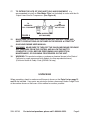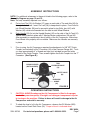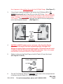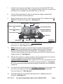
1
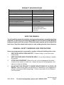
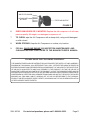
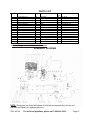
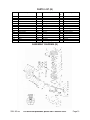
®
AIR COMPRESSOR
6.5 HP / 8 GAL. / GASOLINE POWERED
Model 90749
ASSEMBLY AND OPERATING INSTRUCTIONS
®
3491 Mission Oaks Blvd., Camarillo, CA 93011
Visit our Web site at http://www.harborfreight.com
Copyright© 2003 by Harbor Freight Tools®. All rights reserved. No portion of this
manual or any artwork contained herein may be reproduced in any shape or form
without the express written consent of Harbor Freight Tools.
For technical questions, please call 1-800-444-3353.
Revised Cover Page 10/04
PRODUCT SPECIFICATIONS
Item
Description
Air Tank Capacity
Air Tank Design
8 Gallons
Wheelbarrow Dual Tank System
Maximum Air PSI
115 PSI
Cubic Feet Per Minute Rating
10.3 CFM @ 40 PSI / 8.5 CFM @ 90 PSI
Air Outlet Size
Tank Drain Valve Design
3/8” NPT
Duel Bottom Tank Bleeders
Automatic Compressor Shut-Off
Yes, At 115 PSI
Compressor Cylinder/Crankshaft Construction
Wheel Size / Type
Cast Iron
10”, 4.10/8.5-4, Pneumatic
Power Source
6.5 HP Briggs & Stratton®
Intek® Gasoline Engine
Engine Displacement: 206cc
Recoil Start
SAVE THIS MANUAL
You will need this manual for the safety warnings and precautions, assembly, operating,
inspection, maintenance and cleaning procedures, parts list and assembly diagram.
Keep your invoice with this manual. Write the invoice number on the inside of the
front cover. Keep this manual and invoice in a safe and dry place for future reference.
GENERAL SAFETY WARNINGS AND PRECAUTIONS
Never use compressed air on yourself or another to blow off clothing, skin or hair.
1.
KEEP WORK AREA CLEAN AND DRY. Cluttered, damp, or wet work areas
invite injuries.
2.
KEEP CHILDREN AWAY FROM WORK AREA. Do not allow children to handle
this product.
3.
STORE IDLE EQUIPMENT. When not in use, tools and equipment should be
stored in a dry location to inhibit rust. Always lock up tools and equipment, and
keep out of reach of children.
4.
DO NOT USE THIS PRODUCT IF UNDER THE INFLUENCE OF ALCOHOL OR
DRUGS. Read warning labels on prescriptions to determine if your judgement or
reflexes are impaired while taking drugs. If there is any doubt, do not attempt to
use this product.
REV 10/05; REV 02/06
SKU 90749
For technical questions, please call 1-800-444-3353.
Page 2
5.
6.
USE EYE AND HAND PROTECTION. Wear ANSI approved safety impact eye
goggles and heavy-duty work gloves when using this product. ANSI
approved safety impact eye goggles and heavy-duty work gloves are available
from Harbor Freight Tools.
DRESS SAFELY. Do not wear loose clothing or jewelry, as they can become
caught in moving parts. Wear a protective hair covering to prevent long hair from
becoming caught in moving parts. If wearing a long-sleeve shirt, roll sleeves up
above elbows.
7.
DO NOT OVERREACH. Keep proper footing and balance at all times to prevent
tripping, falling, back injury, etcetera.
8.
INDUSTRIAL APPLICATIONS MUST FOLLOW OSHA REQUIREMENT.
9.
STAY ALERT. Watch what you are doing at all times. Use common sense. Do
not use this product when you are tired or distracted from the job at hand.
10.
CHECK FOR DAMAGED PARTS. Before using this product, carefully check that
it will operate properly and perform its intended function. Check for damaged
parts and any other conditions that may affect the operation of this product.
Replace or repair damaged or worn parts immediately.
11.
REPLACEMENT PARTS AND ACCESSORIES: When servicing, use only
identical replacement parts. Only use accessories intended for use with this
product. Approved accessories are available from Harbor Freight Tools.
12.
MAINTAIN THIS PRODUCT WITH CARE. Keep this product clean and dry for
better and safer performance.
13.
MAINTENANCE: For your safety, service and maintenance should be performed
regularly by a qualified technician.
14.
USE THE RIGHT TOOL FOR THE JOB. Do not attempt to force a small tool or
attachment to do the work of a larger industrial tool. There are certain
applications for which this tool was designed. It will do the job better and more
safely at the rate for which it was intended. Do not modify this tool, and do not use
this tool for a purpose for which it was not intended.
15.
WARNING: The warnings, precautions, and instructions discussed in this manual
cannot cover all possible conditions and situations that may occur. The operator
must understand that common sense and caution are factors, which cannot be
built into this product, but must be supplied by the operator.
SPECIFIC PRODUCT WARNINGS AND PRECAUTIONS
1.
MAINTAIN A SAFE WORKING ENVIRONMENT. Keep the work area well lit.
Make sure there is adequate surrounding workspace. Always keep the work area
free of obstructions, grease, oil, trash, and other debris. Do not use the Air
Compressor in areas near flammable chemicals, dusts, and vapors.
SKU 90749
For technical questions, please call 1-800-444-3353.
Page 3
2.
ALWAYS DISCONNECT THE AIR COMPRESSOR FROM ITS ELECTRICAL
POWER SUPPLY SOURCE, RELEASE ITS AIR PRESSURE, AND
DISCONNECT ALL PNEUMATIC TOOLS FROM THE MACHINE BEFORE
PERFORMING ANY SERVICES OR MAINTENANCE.
3.
WARNING: Make sure to fill the Air Compressor with a premium quality,
30-weight, non-detergent, compressor oil before each use. Running the Air
Compressor with no oil or low oil will cause damage to the equipment and
void the warranty. Note: Optimal capacity of the oil reservoir is 21.5 ounces.
4.
MAKE SURE ALL TOOLS AND EQUIPMENT USED WITH THE AIR
COMPRESSOR ARE RATED TO THE APPROPRIATE PSI CAPACITY. Do not
use any tool or equipment that operates over 115 PSI.
5.
DRAIN AIR COMPRESSOR EVERY DAY. Do not allow moisture to build up
inside the Air Tanks (31). Do not allow the Air Compressor to sit pressurized for
longer than one hour.
6.
DO NOT REMOVE THE FACTORY SEALED PRESSURE RELIEF VALVE
(13).
7.
DO NOT OPEN THE AIR COMPRESSOR TANKS’ DRAIN PLUGS SO THAT
MORE THAN FOUR THREADS ARE SHOWING.
8.
THE AIR COMPRESSOR TANKS’ SAFETY VALVE (42) SHOULD NOT BE
ADJUSTED. This Valve automatically releases air if the Tank pressure exceeds
the preset maximum.
9.
NEVER ATTEMPT TO REPAIR OR MODIFY THE AIR TANKS (31). Welding,
drilling, or any other modification will weaken the Tanks, resulting in damage from
rupture or explosion. Always replace worn, cracked, or damage Tanks.
10.
NEVER OPERATE THE AIR COMPRESSOR WITHOUT ITS SAFETY COVER
(31) ATTACHED AND IN GOOD WORKING ORDER. Air Compressor
scan start automatically without warning. Personal injury and/or property damage
could result from contact with moving parts.
11.
THE AIR COMPRESSOR PARTS MAY BE HOT EVEN IF THE UNIT IS
STOPPED. Keep fingers away from the running Air Compressor. Fast moving
and hot parts will cause injury and/or burns.
12.
DO NOT SPRAY FLAMMABLE MATERIALS IN THE VICINITY OF AN OPEN
FLAME OR NEAR IGNITION SOURCES INCLUDING THE AIR COMPRESSOR
UNIT. Do not direct paint or other sprayed materials at the Air Compressor.
Locate the Air Compressor as far away from the spraying area as possible to
minimize overspray and accumulation on the Air Compressor. Use a face mask/
respirator when spraying, and spray in a well ventilated area to prevent health
and fire hazards. Do not smoke when spraying paint, insecticides, or other
flammable substances. When spraying or cleaning with solvents or toxic
chemicals, follow the instructions provided by the chemical manufacturer.
SKU 90749
For technical questions, please call 1-800-444-3353.
REV 02/04
Page 4
13.
GASOLINE FUEL AND FUMES ARE FLAMMABLE, AND POTENTIALLY
EXPLOSIVE. Use proper fuel storage and handling procedures. Always have
several ABC Class fire extinguishers nearby.
14.
KEEP THE AIR COMPRESSOR AND SURROUNDING AREA’S CLEAN AT
ALL TIMES.
15.
REFILL THE ENGINE WITH GASOLINE OUTDOORS OR ONLY IN WELL
VENTILATED AREAS. Do not store, spill, or use gasoline near an open flame or
heat devices such as a stove, furnace, or water heater which utilize a pilot light or
any device that can produce a spark.
16.
DO NOT REFILL THE ENGINE WITH GASOLINE WHILE THE ENGINE IS
RUNNING OR HOT.
17.
WHEN SPILLS OF FUEL OR OIL OCCUR, THEY MUST BE CLEANED UP
IMMEDIATELY. Dispose of fluids and cleaning materials as per all local, state,
and federal codes and regulations. Store oil rags in a covered metal container.
18.
DO NOT OPERATE THE AIR COMPRESSOR WITH KNOWN LEAKS IN THE
FUEL SYSTEM.
19.
NEVER STORE FUEL OR OTHER FLAMMABLE MATERIALS NEAR THE AIR
COMPRESSOR.
20.
WARNING! CARBON MONOXIDE CAN CAUSE SEVERE NAUSEA,
FAINTING, OR DEATH. DO NOT OPERATE THE AIR COMPRESSOR INSIDE
A CLOSED BUILDING OR A POORLY VENTILATED AREA.
21.
FIRE AND EXPLOSION DANGER. AVOID CONTACT WITH HOT FUEL, OIL,
AND EXHAUST FUMES.
22.
PROLONGED EXPOSURE TO NOISE LEVELS ABOVE 85 dBA IS HAZARDOUS TO HEARING. ALWAYS WEAR ANSI APPROVED HEARING PROTECTION WHEN OPERATING OR WORKING NEAR THE AIR COMPRESSOR
WHEN IT IS RUNNING.
23.
ALWAYS FOLLOW AND COMPLETE SCHEDULED AIR COMPRESSOR AND
ENGINE MAINTENANCE.
24.
CAUTION! THE AIR COMPRESSOR CONTAINS NO AIR COMPRESSOR OIL.
Follow lubrication instructions before operating the Air Compressor.
25.
CAUTION! THE GASOLINE ENGINE (5) CONTAINS NO ENGINE OIL.
Refer to the engine manufacturer’s lubrication instructions before operating the
Engine.
26.
WHEN CHECKING THE ENGINE’S OIL LEVEL: Make sure to unscrew (do not
pull) the Dip Stick out.
SKU 90749
For technical questions, please call 1-800-444-3353.
Page 5
27.
TO EXTEND THE LIFE OF YOUR AIR TOOLS AND EQUIPMENT, it is
recommended to install an Oiler/Water Filter (not included) in series with the Air
Output Line of the Air Compressor. (See Figure A.)
TO
AIR
COMPRESSOR
OUTLET LINE
TO
PNEUMATIC
TOOL / EQUIPMENT
FIGURE A
OILER / WATER FILTER
(NOT INCLUDED)
28.
MAKE SURE TO READ AND UNDERSTAND ALL INSTRUCTIONS AND
®
SAFETY PRECAUTIONS AS OUTLINED IN THE BRIGGS & STRATTON
GASOLINE ENGINE USER MANUAL.
29.
WARNING! MAKE SURE TO TURN OFF THE GASOLINE ENGINE, RELEASE
ALL PRESSURE FROM THE SYSTEM, AND ALLOW THE UNIT TO
COMPLETELY COOL BEFORE PERFORMING ANY INSPECTION,
MAINTENANCE, OR CLEANING PROCEDURES ON THE UNIT.
30.
WARNING: This product contains or produces a chemical known to the State of
California to cause cancer and birth defects (or other reproductive harm).
(California Health & Safety Code § 25249.5 et seq.)
UNPACKING
When unpacking, check to make sure all the parts shown on the Parts List on page 12
and 13 are included. If any parts are missing or broken, please call Harbor Freight Tools
at the number shown on the cover of this manual as soon as possible.
SKU 90749
For technical questions, please call 1-800-444-3353.
Page 6
ASSEMBLY INSTRUCTIONS
NOTE: For additional references to the parts listed in the following pages, refer to the
Assembly Diagram on page 12 and 13.
Note: The only assembly required is as follows.
A.
Put on front Tire (35): An Washer (37) goes on each side of Tire and Axle (36) fits
through hub of wheel. Insert Pin Lock (38) to keep wheel in place. Front Axle fits
into Wheel Brackets (50) and is secured in place by two Bolts (part #41) with
Washer (40), which are threaded into the hole in each Wheel Bracket.
B.
Each Handle (24) fits into the Handle Bracket (45) on the side of the Air Tank (31).
Secure each Handle in place with 2 Washer/Screw combinations (29 and 30).
After assembly is complete test the roll-ability of the Air Compressor. Make sure
Front Wheel rolls properly, with no wobble. Make sure the Handles are securely
in place.
1.
Prior to using, the Air Compressor requires the attachment of a 3/8” NPT Quick
Coupler (not included) to the T-Connector (43) of the Pressure Gauge (44). To do
so, wrap approximately 4” of thread seal tape (not included) around the male
threads of the Quick Coupler. Then, wrench tighten the Quick Coupler into the “T”
Connector. (See Figure B.)
QUICK COUPLER
(NOT INCLUDED)
TOOL
PRESSURE VALVE
(13)
SAFETY VALVE
(42)
T-CONNECTOR
(43)
PRESSURE
GAUGE
(44)
FIGURE B
OPERATING INSTRUCTIONS
1.
2.
CAUTION: ALWAYS make sure the Air Compressor is filled to the proper
level with a premium quality, 30-weight, non-detergent compressor oil prior
to turning on the machine. Failure to do so will result in damage to the Air
Compressor and void its warranty.
To check the level of oil in the Air Compressor, observe the Oil Window (B23)
located on the Crank Shaft Case (16). Proper oil level is indicated when
REV 02/04
SKU 90749
For technical questions, please call 1-800-444-3353.
Page 7
the oil appears in the middle of the circle in the Oil Sight Gauge. (See Figure C.)
3.
If the oil level is below the middle of the circle in the Oil Window (B23), UNSCREW (do not pull) the Oil Cap (23) out of the Oil Fill Hole. Next, add oil into
the Oil Fill Hole until the level of oil reaches the middle of the circle as indicated
in the Oil Window. Do not overfill. Note: Optimal capacity of the oil reservoir is
21.5 ounces. Then screw the Oil Cap back onto the Oil Fill Hole, being careful
not to strip the plastic threads.
(See Figure C.)
FRONT VIEW
SIDE VIEW
OIL CAP
(23)
OIL
WINDOW
(B23)
FIGURE C
4.
CAUTION: ALWAYS make sure the crankcase of the Gasoline Engine
(5) is filled to the proper level with a premium quality, 30-weight, nondetergent engine oil prior to starting the engine. Failure to do so will result
in damage to the Air Compressor and void its warranty. Refer to the engine
manufacturer’s instruction manual for further information.
5.
Check to make sure the Drain Plugs on both Air Tanks (31) are fully closed.
(See Figures D, and E.)
TYPICAL DRAIN PLUGS
1/4” HEX
PIPE
FIGURE D
6.
Turn the Tool Pressure Valve (13) clockwise all the way to allow compressed air
to build up in the Air Tanks (31). (See Figure B.)
REV 02/04
SKU 90749
For technical questions, please call 1-800-444-3353.
Page 8
7.
Connect the air hose (not provided) to the previously installed 3/8” NPT Quick
Coupler on the Air Outlet Line. Then, connect the other end of the air hose to the
pneumatic tool or equipment (not provided) that is to be used.
8.
Start the Gasoline Engine (5). Refer to the Gasoline Engine manufacturer’s
instruction manual for further information.
9.
Allow sufficient time for the Air Tanks’ Pressure Gauge (27) to indicate at least 80
PSI before using the Air Compressor. (See Figure I.)
AIR FILTER (B4)
SAFETY COVER (31)
CONTROL VALVE ASSEMBLY
(22)
GASOLINE ENGINE (5)
PRESSURE GAUGE
(44)
PRESSURE GAUGE (27)
SAFETY VALVE (42)
AIR OUTLET LINE
TIRE (35)
DRAIN PLUG
AIR TANK (31)
FIGURE E
10.
Turn the Control Valve Assembly (22) counterclockwise to allow air to the
pneumatic tool. (See Figures B, and E.)
11.
NOTE: When adjusting the air pressure being forwarded to the pneumatic tool,
you will need to compare the pressure readings of both the Tanks’ Pressure
Gauge (27) and the outlet Pressure Gauge (44). The reading on the Tanks’
Pressure Gauge dictates the maximum air pressure at which the outlet Pressure
Gauge may be set. (See Figure E.)
12.
With the Air Compressor running, and the air hose and pneumatic tool hooked up
to the Air Compressor, turn the Control Valve Assembly (22)
counterclockwise to increase the air output to the tool, up to the maximum rated
pressure (115 PSI) as indicated on the Tanks’ Pressure Gauge (27). (See Figure
E.) In any case never exceed the pressure rating of the hose or tool connected to
compressor.
13.
Turn the Control Valve Assembly (22) clockwise to decrease the air output to the
tool, down to the minimum rated pressure (0 PSI) as indicated on the Tanks’
Pressure Gauge (27). (See Figure E.)
14.
The Safety Valve (42) is used when decompression is needed quickly and
efficiently. (See Figure B.)
SKU 90749
For technical questions, please call 1-800-444-3353.
Page 9
15.
In the event fast decompression of the Air Tanks (39) is required, immediately turn
off the Gasoline Engine (part #5) and pull out on the Pull Ring of the Safety Valve
(42) until both Air Tanks have fully decompressed.
(See Figures B, and E.)
16.
Pull out on the Safety Valve (42) to immediately release air pressure in the Air
Tanks (31). (See Figure I.)
17.
When finished using the Air Compressor, turn off the Gasoline Engine
(5), and pull out on the Pull Ring of the Safety Valve (42) until both Air Tanks (31)
have fully decompressed. (See Figures B, and E.)
INSPECTION, MAINTENANCE, AND CLEANING
1.
CAUTION! Always release all pressure from the system and disconnect all
tools from the Air Compressor before performing any inspection, maintenance,
or cleaning. Be aware that the sudden release of air from any valve or air tool can
present a danger to one’s ears.
2.
BEFORE EACH USE, inspect the general condition of the Air Compressor.
Check all air fittings for leaks. Check for loose screws, misalignment or binding of
moving parts, cracked or broken parts, damaged, and any other condition that
may affect the safe operation of this tool. If abnormal noise or vibration occurs,
immediately release all pressure from the system and have the problem
corrected before further use. Do not use damaged equipment.
3.
DAILY: EMPTY CONDENSATION FROM THE AIR TANKS (31).
The Drain Plugs are located underneath each Air Tank, and should be used daily
to release all trapped moisture that may cause Air Tank corrosion. Slowly and
carefully unscrew (no more than four threads) the Drain Plugs until the
condensation begins to be released from the Air Tanks. Allow sufficient time for
all of the condensation to escape from the Air Tanks. Then, firmly retighten the
Drain Plugs. (See Figure E.)
4.
DAILY: Check the Air Compressor oil level. If necessary, fill with a premium
quality, 30-weight, non-detergent, compressor oil. NOTE: When checking the
Air Compressor oil level, make sure to unscrew (do not pull) the Oil Cap (23).
5.
EVERY 100 HOURS OF USE: Clean the Air Filter (B4) with a mild solvent. Then,
dry and reattach the Air Filter Sleeve. (Replace the Air Filter Sleeve if it is too
dirty to properly clean.) To clean or replace the Air Filter Sleeve, remove the two
Hex Socket Set Bolts. Remove the Air Filter Cover. Remove the Air Filter Sleeve
and clean. Then, replace the Air Filter Sleeve and two Hex Socket Set Bolts.
(See Figures E, and F.)
SKU 90749
REV 02/04
For technical questions, please call 1-800-444-3353.
Page 10
AIR FILTER COVER
HEX SOCKET
SET BOLT
FILTER AIR SLEEVE
FIGURE F
6.
EVERY 500 HOURS OR 12 MONTHS: Replace the old compressor oil with new,
premium quality, 30-weight, non-detergent, compressor oil.
7.
TO CLEAN, wipe the Air Compressor with a damp cloth, using a mild detergent
or mild solvent.
8.
WHEN STORING, Keep the Air Compressor in a clean, dry location.
9.
FOR ALL GASOLINE ENGINE (25) INSPECTION, MAINTENANCE, AND
CLEANING INSTRUCTIONS REFER TO THE MANUFACTURER’S MANUAL.
PLEASE READ THE FOLLOWING CAREFULLY
THE MANUFACTURER AND/OR DISTRIBUTOR HAS PROVIDED THE PARTS LIST AND ASSEMBLY
DIAGRAM IN THIS MANUAL AS A REFERENCE TOOL ONLY. NEITHER THE MANUFACTURER OR
DISTRIBUTOR MAKES ANY REPRESENTATION OR WARRANTY OF ANY KIND TO THE BUYER THAT
HE OR SHE IS QUALIFIED TO MAKE ANY REPAIRS TO THE PRODUCT, OR THAT HE OR SHE IS
QUALIFIED TO REPLACE ANY PARTS OF THE PRODUCT. IN FACT, THE MANUFACTURER AND/OR
DISTRIBUTOR EXPRESSLY STATES THAT ALL REPAIRS AND PARTS REPLACEMENTS SHOULD BE
UNDERTAKEN BY CERTIFIED AND LICENSED TECHNICIANS, AND NOT BY THE BUYER. THE BUYER
ASSUMES ALL RISK AND LIABILITY ARISING OUT OF HIS OR HER REPAIRS TO THE ORIGINAL
PRODUCT OR REPLACEMENT PARTS THERETO, OR ARISING OUT OF HIS OR HER INSTALLATION
OF REPLACEMENT PARTS THERETO.
SKU 90749
For technical questions, please call 1-800-444-3353.
Page 11
PARTS LIST
Part #
1
2
3
4
5
6
7
8
9
10
11
12
13
14
15
Description
Belt Guard Inner
Screw
Washer
Belt Guard Outer
Gasoline Engine *
Washer
Nut
Belt Pulley (Engine)
Belt
Bolt
Nut
Support Bar
Nut
Washer
Compressor Pump
Part #
16
17
18
19
20
21
22
23
24
25
26
27
28
29
30
Description
Air Tube
Bolt
Flat Washer
Spring Washer
Nut
Control Wire
Control Valve Assembly
Handle Grip
Handle
Air Pressure Regulator
Hose Connector (output)
Pressure Gauge (output)
Water Drainer
Washer
Screw
Par
t#
31
32
33
34
35
36
37
38
39
40
41
42
43
44
45
Description
Air Tank
Nut
Bolt
Rubber Foot
Pneumatic Tire
Axle
Washer
Lock Pin
Spring Washer
Flat Washer
Bolt
Safety Valve
T-Connector
Pressure Gauge (Tank)
Handle Bracket
* See Briggs & Stratton Engine Parts List and
Assembly Diagram for ®available replacement parts.
ASSEMBLY DIAGRAM
45
NOTE: Some parts are listed and shown for illustration purposes only, and are not
available individually as replacement parts.
SKU 90749
For technical questions, please call 1-800-444-3353.
Page 12
PARTS LIST (B)
Part #
1
2
3
4
5
6
7
8
9
10
11
12
13
14
15
Description
Part #
Flat Washer
Screw
Screw
Air Filter
Cylinder Head
Air Connector (output)
Gasket
Valve Seat Plate
Gasket
Valve Plate
Gasket
Cylinder
Gasket
Bolt
Washer
16
17
18
19
20
21
22
23
24
25
26
27
28
29
30
Description
Crank Shaft Case
Gasket
Dip Stick
Flat Washer
Spring Washer
Screw
End Plate
Oil Window
O Ring Seal
Screw
O Ring Seal
Bottom Plate
Gasket
Bearing
Retaining Ring
Par
t#
31
32
33
34
35
36
37
38
39
40
41
42
43
44
45
Description
Crank Shaft
Oil Seal
Cover Plate
Screw
Spring Washer
Flat Washer
Belt Pulley
Connecting Rod
Piston PI
Retaining Ring
Piston
Piston Ring
Screw
Washer
Gasket
ASSEMBLY DIAGRAM (B)
SKU 90749
For technical questions, please call 1-800-444-3353.
Page 13