1
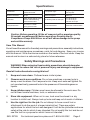
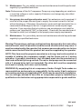
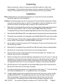
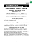
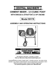
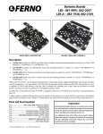
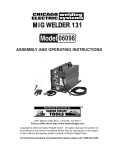
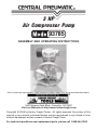
3 HP
Air Compressor Pump
93785
ASSEMBLY AND OPERATING INSTRUCTIONS
Due to continuing improvements, actual product may differ slightly from the product described herein.
3491 Mission Oaks Blvd., Camarillo, CA 93011
Visit our Web site at http://www.harborfreight.com
Copyright © 2006 by Harbor Freight Tools®. All rights reserved. No portion of this
manual or any artwork contained herein may be reproduced in any shape or form
without the express written consent of Harbor Freight Tools.
For technical questions and replacement parts, please call 1-800-444-3353
Specifications
Construction:
Cast Aluminum Pump,
Flywheel and Head.
Compressor Type:
Single Stage,
Twin Cylinder
Maximum Pressure:
1 4 0 p si
Maximum Speed:
1200 rpm
Lubrication:
Splash Oil type with Oil Level
Window and Ball Bearing
Check Release Valve
Air Delivery Rate at 1050 rpm:
8.7 cfm at 40 psi
7.7 cfm at 90 psi
6.95 cfm at 115 psi
Pulley Dimensions:
10-¼" Dia. x 1-3/8"W
with V-groove for belt
Piston Dimensions:
65mm Dia. x 50mm stroke
Overall Dimensions:
12-¼"L x 10-¼"W x 12-¼"H
Net Weight:
23 lbs.
Caution: Before operating, fill the oil reservoir with a premium quality,
30-weight, nondetergent oil before operating. Running the Air
Compressor Pump with little or no oil will cause damage to the pump
and void the warranty.
Save This Manual
You will need the manual for the safety warnings and precautions, assembly instructions,
operating and maintenance procedures, parts list and diagram. Keep your invoice
with this manual. Write the invoice number on the inside of the front cover. Keep the
manual and invoice in a safe and dry place for future reference.
Safety Warnings and Precautions
WARNING: When using tool, basic safety precautions should always be
followed to reduce the risk of personal injury and damage to equipment.
Read all instructions before using this tool!
1.
Keep work area clean. Cluttered areas invite injuries.
2.
Observe work area conditions. Do not use machines or power tools in
damp or wet locations. Don’t expose to rain. Keep work area well lighted. Do
not use electrically powered tools in the presence of flammable gases or
liquids.
3.
Keep children away. Children must never be allowed in the work area. Do
not let them handle machines, tools, or extension cords.
4.
Store idle equipment. When not in use, tools must be stored in a dry
location to inhibit rust. Always lock up tools and keep out of reach of children.
5.
Use the right tool for the job. Do not attempt to force a small tool or
attachment to do the work of a larger industrial tool. There are certain
applications for which this tool was designed. It will do the job better and more
safely at the rate for which it was intended. Do not modify this tool and do not
use this tool for a purpose for which it was not intended.
SKU 93785
For technical questions please call 1-800-444-3353
Page 2
6.
Dress properly. Do not wear loose clothing or jewelry as they can be caught
in moving parts. Protective, electrically non-conductive clothes and non-skid
footwear are recommended when working. Wear restrictive hair covering to
contain long hair.
7.
Use eye and ear protection. Always wear ANSI approved impact safety
goggles. Wear a full face shield if you are producing metal filings or wood
chips. Wear an ANSI approved dust mask or respirator when working around
metal, wood, and chemical dusts and mists.
8.
Do not overreach. Keep proper footing and balance at all times. Do not reach
over or across running machines.
9.
Maintain tools with care. Keep tools maintained and clean for better and
safer performance. Follow instructions for lubricating and changing
accessories. Inspect tool cords periodically and, if damaged, have them
repaired by an authorized technician.
10. Disconnect power. Unplug drive motor when not in use.
11. Remove adjusting keys and wrenches. Check that keys and adjusting
wrenches are removed from the tool or machine work surface before starting work.
12. Avoid unintentional starting. Be sure the drive motor power switch is in the
Off position when not in use and before plugging in.
13. Stay alert. Watch what you are doing, use common sense. Do not operate
any tool when you are tired.
14. Check for damaged parts. Before using any tool, any part that appears
damaged should be carefully checked to determine that it will operate properly
and perform its intended function. Check for alignment and binding of moving
parts; any broken parts or mounting fixtures; and any other condition that may
affect proper operation. Any part that is damaged should be properly repaired
or replaced by a qualified technician. Do not use the tool if any switch does
not turn On and Off properly.
15. Guard against electric shock. Prevent body contact with grounded surfaces
such as pipes, radiators, ranges, and refrigerator enclosures.
16. Replacement parts and accessories. When servicing, use only identical
replacement parts. Use of any other parts will void the warranty. Only use
accessories intended for use with this tool. Approved accessories are
available from Harbor Freight Tools.
17. Do not operate tool if under the influence of alcohol or drugs. Read
warning labels if taking prescription medicine to determine if your judgment or
reflexes are impaired while taking drugs. If there is any doubt, do not operate
the tool.
SKU 93785
For technical questions please call 1-800-444-3353
Page 3
18. Maintenance. For your safety, service and maintenance should be performed
regularly by a qualified technician.
Note: Performance of this Air Compressor Pump may vary depending on variations
in local line voltage or motor capacity. Extension cord usage may also affect
tool performance.
19. Use proper size and type extension cord. If an extension cord is required, it
must be of the proper size and type to supply the correct current to the tool
without heating up. Otherwise, the extension cord could melt and catch fire, or
cause electrical damage to the tool. Longer extension cords require larger
size wire. If you are using the tool outdoors, use an extension cord rated for
outdoor use. (signified by “WA” on the jacket). Check with the manufacturer of
the electric motor (not included) for the proper power supply requirements.
20. Maintenance. For your safety, service and maintenance should be performed
regularly by a qualified technician.
Warning: The warnings, cautions, and instructions discussed in this instruction
manual cannot cover all possible conditions and situations that may occur. It
must be understood by the operator that common sense and caution are factors
which cannot be built into this product, but must be supplied by the operator.
NOTE: This item must be properly mounted on a strong, level surface which is
capable of holding the compressor weight, and the forces put on it during
operation. A properly sized motor (not included) must also be mounted on a
level and sufficiently strong surface. The motor and pump must be connected
with a V shaped drive belt (not included). The drive belt must be completely
enclosed in a sturdy belt cover (not included).
WARNING: By supplying this air compressor, Harbor Freight Tools makes no
representations and accepts no responsibility for the motor, V-belt, enclosure
or mounting surface not supplied by HFT which may be used in the installation.
You are strongly advised to have this air compressor properly installed by a
qualified service technician using appropriate components in good condition.
REV 02/07
SKU 93785
For technical questions please call 1-800-444-3353
Page 4
Air Compressor Pump Safety Precautions
1.
Use proper size motor and motor pulley. This air compressor Pump must
be installed with a 3 HP electric motor and pulley (both not supplied) which
can turn the Air Compressor Belt Wheel (35) at approximately 1050 rpm, but
not more than 1200 rpm.
2.
Install motor, pully belt and pully belt cover securely. Be sure to use the
proper size bolts to install your motor (not included). The belt and belt cover
(not included) must be strong enough to prevent breaking and possible injury.
3.
Be sure all equipment is rated to the appropriate capacity of this pump.
Make sure that the lowest rated piece of equipment you are using can handle
the maximum pressure of the Air Compressor Pump (see Specifications).
4.
Avoid explosions and fire. Never place flammable objects near the compressor.
Never spray water or any flammable liquids towards the compressor.
5.
Avoid bodily injury. Never direct the air outlet at any person or animal.
6.
Use Safety Guard for Pulleys. The Air Compressor Belt Wheel (35), V-belt
(not supplied), and motor pulley (not supplied) must be covered by a safety
guard (not supplied) covering all moving elements before operation.
7.
Avoid burns. The Cylinder (12), Cylinder Head (5) and Air Outlet (6) become
very hot during operation. Do not touch.
8.
Industrial Applications. If used in an industrial applications, you must follow
OSHA requirements.
9.
Properly fill Air Compressor Pump oil reservoir before operating. Fill
the oil reservoir with a premium quality, 30-weight, non-detergent oil before
operating. Check oil level through the Oil Level Window before each use.
Running the Air Compressor Pump with little or no oil will cause damage to
the pump and void the warranty.
Recommended Compressed Air System Components
We recommend that you use both a filter and an in-line oiler in your air supply system
as illustrated in the diagram below. These components are not included with this tool,
but are available from Harbor Freight Tools.
Air Tool
SKU 93785
For technical questions please call 1-800-444-3353
Page 5
Unpacking
When unpacking, check to make sure that the product is intact and
undamaged. If any parts are missing or broken, please call Harbor Freight
Tools at the number on the cover of this manual as soon as possible.
Installation
Note: Depending on your level of expertise, you may wish to have a qualified
technician perform this installation.
Caution: Avoid damage to the Air Compressor Pump and other equipment. Make
sure the mounting surface for the Air Compressor Pump is installed on a flat
and level surface, strong enough to support the pump and motor.
1.
Place the Air Compressor Pump on the mounting surface at the same level as the 3
HP motor used to drive it. The 14-¼ inch V-groove Belt Wheel (35) of the Air
Compressor Pump must be in perfect alignment with the motor pulley (not included).
2.
Verify that the Belt Wheel (35) turns freely where it overhangs the mounting surface.
3.
Place the V-groove belts (not included) over the Belt Wheel (35) and motor pulley.
4.
Pull Compressor Pump until properly aligned, and the belt is tight. Recheck
motor pulley, V-groove belt, and Belt Wheel alignment.
5.
Use a pencil to mark through the Air Compressor Pump mounting holes onto
the mounting surface.
6.
Move the Air Compressor Pump and drill four 3/8 inch holes in the mounting surface.
7.
Move the Air Compressor Pump back to its mounting position.
8.
Secure each corner of the base with a 3/8 inch diameter bolt, washer, lock
washer, and nut (all not supplied).
9.
Make final alignment and belt tightness adjustments from the motor. It may be
necessary to loosen the motor mounting bolts to adjust the motor location. To
test the proper tension on the V-belts, press down on the belts, they should
not depress more than 1/2 inch at mid-point. Tighten all mounting hardware.
10. Mount the motor (not supplied) as recommended by the motor manufacturer.
Be sure that the motor is securely mounted.
11. Connect plumbing hardware (not supplied) from the male ½” - 14 tpi Air Outlet
(6) to the air destination (i.e., air pressure tank, not supplied).
12.
Install a safety guard (not supplied) that surrounds the motor pulley, V-belts,
and Belt Wheel (35). This safety guard must cover all sides of the moving
belts and pulleys. It should have a clearance of about one inch from the
moving parts. The safety guard must be sturdy enough to prevent injury.
SKU 93785 For technical questions please call 1-800-444-3353
Page 6
Note: A qualified electrician must wire in a pressure switch control that turns off
the motor when the pump reaches the desired pressure (less than 140 PSI).
Note: Always install this Air Compressor Pump to an air tank that has a pressure
release valve set at less than 140 PSI.
Note: A high/low cut-in/cut-out switch (not included) can be incorporated to operate
a motor starter or motor contractor for semi-automatic control of air pressure
in the vessel.
Warning: Avoid serious injuries. Do not operate this Air Compressor Pump without
the Safety Guard in place.
Air Filter (4)
13. Unscrew the Oil Filler Cap (44) and fill the oil
reservoir to mid point as seen in the Oil Window
(22). The oil should be premium qualify, 30weight, non-detergent oil. Do not overfill.
Operation
1.
Turn on the power switch to the drive motor.
2.
Check the following items:
- V-belt should not vibrate.
- Listen for air leaks.
- Listen for abnormal noise or vibration.
Oil Filler Cap (44)
- If there is a problem, turn power off and
release air pressure from the line before attempting repairs.
Oil Window (22)
3.
Allow Air Compressor Pump to cool down after each hour of use.
4.
Turn off the power switch to the drive motor when finished using the Air
Compressor Pump. Do not leave on if the compressed air is not being used.
Maintenance
Caution: Remove power from the drive motor before attempting any maintenance
on the Air Compressor Pump.
1.
Before each use, verify that the oil level is at the proper level as viewed through
the Oil Window (22).
2.
Periodically check V-belts for proper tension.
3.
Periodically remove Air Filter (4) and blow clean with compressed air. If it is
dark in color and will not blow clean, replace the filter.
4.
If the oil appears dirty, open the Oil Filler Cap (44), and remove the Oil Drain
Bolt (24), capturing the oil in a suitable container. Dispose of the used oil in
accordance with local regulations. Replace the Oil Drain Bolt, and refill as
discussed in item 12 above.
SKU 93785 For technical questions please call 1-800-444-3353
Page 7
Parts List
Part # Description
QTY.
Part # Description
QTY.
1
Washer
16
23
Oil Window Gasket
1
2
Bolt
14
24
Oil Drain Bolt
1
3
Screw
6
25
S eal
1
4
Air Filter
2
26
Gasket
1
5
Cylinder Head
1
27
Base Cover
1
6
Air Outlet
1
28
Bearing
2
7*
Gasket Valve Seat
1
29
Crankshaft
1
8*
Valve Seat
1
30
Oil Seal
1
9*
Gasket Valve Seat
4
31
End Cover
1
10*
Valve Plate
1
32
Screw
1
11*
Cylinder Head Gasket
4
33
Spring Washer
1
12
Cylinder
1
34
Washer
1
13
Screw
1
35
Belt Wheel
1
14
Cylinder Gasket
6
36
Nut
1
15
Dipstick
1
37
Screw
4
16
Crankshaft Case
1
38
Connecting Rod
2
17
Gasket
1
39
Piston Pin
2
18
Gasket
2
40
Lock Ring
4
19
Washer
1
41
Piston
2
20
Spring Washer
6
42**
Piston Oil Ring
2
21
Bolt
1
43**
Piston Air Ring
4
22
Oil Window
1
44
Oil Filler Cap (not shown)
1
45
Cylinder Gasket & Reed Valve Kit
1
46
Piston Ring Kit
1
NOTE: Parts # 7*-11* are sold only as an assembly called the “Cylinder Gasket &
Reed Valve Kit”. Parts number # 42** and 43** are sold only as a set called “Piston
Ring Set”.
NOTE: Some parts are listed and shown for illustration purposes only and are not
available individually as replacement parts.
SKU 93785
For technical questions please call 1-800-444-3353
Page 8
Assembly Drawing
44
PLEASE READ THE FOLLOWING CAREFULLY
THE MANUFACTURER AND/OR DISTRIBUTOR HAS PROVIDED THE PARTS DIAGRAM
IN THIS MANUAL AS A REFERENCE TOOL ONLY. NEITHER THE MANUFACTURER NOR
DISTRIBUTOR MAKES ANY REPRESENTATION OR WARRANTY OF ANY KIND TO THE
BUYER THAT HE OR SHE IS QUALIFIED TO MAKE ANY REPAIRS TO THE PRODUCT OR
THAT HE OR SHE IS QUALIFIED TO REPLACE ANY PARTS OF THE PRODUCT. IN FACT,
THE MANUFACTURER AND/OR DISTRIBUTOR EXPRESSLY STATES THAT ALL REPAIRS
AND PARTS REPLACEMENTS SHOULD BE UNDERTAKEN BY CERTIFIED AND
LICENSED TECHNICIANS AND NOT BY THE BUYER. THE BUYER ASSUMES ALL RISK
AND LIABILITY ARISING OUT OF HIS OR HER REPAIRS TO THE ORIGINAL PRODUCT
OR REPLACEMENT PARTS THERETO, OR ARISING OUT OF HIS OR HER INSTALLATION
OF REPLACEMENT PARTS THERETO.
SKU 93785
For technical questions please call 1-800-444-3353
Page 9