1
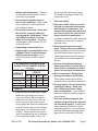
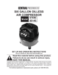
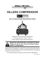
Oilless COMPRESSOR
90168
Set up and Operating Instructions
Distributed exclusively by Harbor Freight Tools®.
3491 Mission Oaks Blvd., Camarillo, CA 93011
Visit our website at: http://www.harborfreight.com
Read this material before using this product.
Failure to do so can result in serious injury.
Save this manual.
Copyright© 2003 by Harbor Freight Tools®. All rights reserved. No portion of this manual or any artwork
contained herein may be reproduced in any shape or form without the express written consent of
Harbor Freight Tools. Diagrams within this manual may not be drawn proportionally. Due to continuing
improvements, actual product may differ slightly from the product described herein. Tools required for
assembly and service may not be included.
For technical questions or replacement parts, please call 1-800-444-3353.
Manual revised 08h
NOTICE is used to
address practices
not related to personal injury.
Save This Manual
Keep this manual for the safety warnings and precautions, assembly, operating, inspection, maintenance and cleaning
procedures. Write the product’s serial
number in the back of the manual near the
assembly diagram (or month and year of
purchase if product has no number). Keep
this manual and the receipt in a safe and
dry place for future reference.
CAUTION, without
the safety alert
symbol, is used to address
practices not related to
personal injury.
General Safety Warnings
WARNING Read all safety
warnings and instructions.
Failure to follow the warnings
and instructions may result in
explosion, fire and/or serious
injury.
Save all warnings and
instructions for future reference.
Important SAFETY
Information
In this manual, on the labeling,
and all other information provided with this product:
This is the safety alert
symbol. It is used to alert
you to potential personal
injury hazards. Obey all
safety messages that
follow this symbol to avoid
possible injury or death.
1.
a.Keep work area clean and well lit.
Cluttered or dark areas invite accidents.
b.Do not operate compressors in
explosive atmospheres, such as in
the presence of flammable liquids,
gases or dust. Compressors become hot which may ignite the dust
or fumes.
DANGER indicates
a hazardous
situation which, if not
avoided, will result in death or
serious injury.
WARNING
indicates a
hazardous situation which, if
not avoided, could result in
death or serious injury.
c.Keep children and bystanders
away while operating a compressor. Distractions can cause you to
lose control.
CAUTION, used
with the safety
alert symbol, indicates a
hazardous situation which, if
not avoided, could result in
minor or moderate injury.
SKU 90168
Work area safety
2.
Electrical safety
a.Compressor plugs must match the
outlet. Never modify the plug in
any way. Do not use any adapter
plugs with grounded compressors.
Unmodified plugs and matching outlets will reduce risk of electric shock.
b.Avoid body contact with grounded
surfaces such as pipes, radiators,
For technical questions, please call 1-800-444-3353.
Page 2
ranges and refrigerators. There is
an increased risk of electric shock if
your body is grounded.
c.Do not expose compressors to
rain or wet conditions. Water entering a compressor will increase the
risk of electric shock.
d.Do not abuse the cord. Never use
the cord for carrying, pulling or
unplugging the compressor. Keep
cord away from heat, oil, sharp
edges or moving parts. Damaged
or entangled cords increase the risk
of electric shock.
e.If operating a compressor in a
damp location is unavoidable, use
a Ground Fault Circuit Interrupter
(GFCI) protected supply. Use of
a GFCI reduces the risk of electric
shock.
RECOMMENDED MINIMUM WIRE
GAUGE FOR EXTENSION CORDS
(120 VOLT)
NAMEPLATE
AMPERES
(at full load)
EXTENSION CORD
LENGTH
25’
50’ 100’ 150’
0–6
18
16
16
14
6.1 – 10
18
16
14
12
10.1 – 12
16
16
14
12
12.1 – 16
14
12
Do not use.
TABLE A
f. USE PROPER EXTENSION CORD.
Make sure your extension cord is
in good condition. When using an
extension cord, be sure to use one
heavy enough to carry the current
your product will draw. An undersized
cord will cause a drop in line voltage
resulting in loss of power and overheating. Table A shows the correct
size to use depending on cord length
and nameplate ampere rating. If in
SKU 90168
doubt, use the next heavier gage.
The smaller the gage number, the
heavier the cord.
3.
Personal safety
a.Stay alert, watch what you are doing and use common sense when
operating this compressor. Do
not use this compressor while you
are tired or under the influence of
drugs, alcohol or medication. A
moment of inattention while operating
compressors may result in serious
personal injury.
b.Use personal protective equipment. Always wear eye protection.
Safety equipment such as dust mask,
non-skid safety shoes, hard hat, or
hearing protection used for appropriate conditions will reduce personal
injuries.
c.Prevent unintentional starting.
Ensure the switch is in the off-position before connecting to power
source or moving the compressor.
d.Do not overreach. Keep proper
footing and balance at all times.
This enables better control of the
compressor in unexpected situations.
e.Dress properly. Do not wear loose
clothing or jewelry. Keep your
hair, clothing and gloves away
from moving parts. Loose clothes,
jewelry or long hair can be caught in
moving parts.
f. Only use safety equipment that
has been approved by an appropriate standards agency. Unapproved
safety equipment may not provide
adequate protection. Eye protection
must be ANSI-approved and breathing protection must be NIOSH-ap-
For technical questions, please call 1-800-444-3353.
Page 3
proved for the specific hazards in the
work area.
4.
5.
a.Have your compressor serviced
by a qualified repair person using
only identical replacement parts.
This will ensure that the safety of the
compressor is maintained.
Compressor use and care
a.Do not force the compressor. Use
the correct compressor for your
application. The correct compressor
will do the job better and safer at the
rate for which it was designed.
b.Do not use the compressor if the
switch does not turn it on and off.
Any compressor that cannot be controlled with the switch is dangerous
and must be repaired.
c.Disconnect the plug from the
power source of the compressor
before making any adjustments,
changing accessories, or storing compressors. Such preventive
safety measures reduce the risk of
starting the compressor accidentally.
d.Store idle compressors out of the
reach of children and do not allow
persons unfamiliar with the compressor or these instructions to
operate it. Compressors are dangerous in the hands of untrained users.
e.Maintain compressors. Check for
misalignment or binding of moving
parts, breakage of parts and any
other condition that may affect the
compressor’s operation. If damaged, have the compressor repaired before use. Many accidents
are caused by poorly maintained
compressors.
f. Use the compressor in accordance
with these instructions, taking into
account the working conditions
and the work to be performed. Use
of the compressor for operations
different from those intended could
result in a hazardous situation.
SKU 90168
Service
Air Compressor Safety Warnings
1.
Risk of fire or explosion - do not
spray flammable liquid in a confined
area or towards a hot surface. Spray
area must be well-ventilated. Do not
smoke while spraying or spray where
spark or flame is present. Arcing
parts - keep compressor at least 20
feet away from explosive vapors,
such as when spraying with a spray
gun.
2.
Risk of bursting - do not adjust
regulator to result in output pressure
greater than marked maximum pressure of attachment.
3.
Risk of injury - do not direct air
stream at body. To reduce the risk of
electric shock, do not expose to rain.
Store indoors.
4.
Do not use to supply breathing air.
5.
Do not direct air flow from the Compressor at people or animals.
6.
Industrial applications must follow
OSHA requirements.
7.
Maintain labels and nameplates on
the compressor. These carry important safety information. If unreadable
or missing, contact Harbor Freight
Compressors for a replacement.
8.
Avoid unintentional starting. Prepare
to begin work before turning on the
compressor.
For technical questions, please call 1-800-444-3353.
Page 4
9.
This product is not a toy. Keep it out
of reach of children.
10. WARNING: The brass components
of this product contain lead, a chemical known to the State of California
to cause birth defects (or other reproductive harm). (California Health &
Safety code § 25249.5, et seq.)
11. People with pacemakers should
consult their physician(s) before use.
Electromagnetic fields in close proximity to heart pacemaker could cause
pacemaker interference or pacemaker failure. In addition, people with
pacemakers should:
• Avoid operating alone.
• Do not use with power switch locked
on.
• Properly maintain and inspect to
avoid electrical shock.
• Any power cord must be properly
grounded. Ground Fault Circuit Interrupter (GFCI) should also be implemented – it prevents sustained electrical shock.
those dust masks that are specially
designed to filter out microscopic
particles. (California Health & Safety
Code § 25249.5, et seq.)
13. WARNING: Handling the cord on
this product will expose you to lead,
a chemical known to the State of
California to cause cancer, and birth
defects or other reproductive harm.
Wash hands after handling. (California Health & Safety Code § 25249.5,
et seq.)
14. The warnings, precautions, and instructions discussed in this instruction
manual cannot cover all possible conditions and situations that may occur.
It must be understood by the operator
that common sense and caution are
factors which cannot be built into this
product, but must be supplied by the
operator.
Save these
instructions.
12. Some dust created by power sanding, sawing, grinding, drilling, and
other construction activities, contains
chemicals known [to the State of California] to cause cancer, birth defects
or other reproductive harm. Some
examples of these chemicals are:
• Lead from lead-based paints
• Crystalline silica from bricks and cement or other masonry products
• Arsenic and chromium from chemically treated lumber
Your risk from these exposures varies, depending on how often you do
this type of work. To reduce your
exposure to these chemicals: work in
a well ventilated area, and work with
approved safety equipment, such as
SKU 90168
For technical questions, please call 1-800-444-3353.
Page 5
instructions are not completely understood, or if in doubt as to whether the
compressor is properly grounded.
Grounding Instructions
To prevent
electric shock
and death from
incorrect grounding
wire connection
Read and follow these
instructions:
5.
Use only 3-wire extension cords that
have 3-prong grounding plugs and
3-pole receptacles that accept the
compressor’s plug.
6.
Repair or replace damaged or worn
cord immediately.
7.
This compressor is intended for use
on a circuit that has an outlet that
looks like the one illustrated above
in 125 V~ 3-Prong Plug and Outlet.
The compressor has a grounding
plug that looks like the plug illustrated
above in 125 V~ 3-Prong Plug and
Outlet.
8.
The outlet must be properly installed
and grounded in accordance with all
codes and ordinances.
9.
Do not use an adapter to connect this
compressor to a different outlet.
Grounded Compressors:
Compressors with Three Prong
Plugs
1.
2.
3.
4.
In the event of a malfunction or
breakdown, grounding provides a
path of least resistance for electric
current to reduce the risk of electric
shock. This compressor is equipped
with an electric cord having an
equipment-grounding conductor and
a grounding plug. The plug must be
plugged into a matching outlet that
is properly installed and grounded in
accordance with all local codes and
ordinances.
Do not modify the plug provided – if it
will not fit the outlet, have the proper
outlet installed by a qualified electrician.
Improper connection of the equipment-grounding conductor can result in a risk of electric shock. The
conductor with insulation having an
outer surface that is green with or
without yellow stripes is the equipment-grounding conductor. If repair
or replacement of the electric cord or
plug is necessary, do not connect the
equipment-grounding conductor to a
live terminal.
Check with a qualified electrician or
service personnel if the grounding
SKU 90168
For technical questions, please call 1-800-444-3353.
Page 6
Double Insulated Compressors:
Compressors with Two Prong
Plugs
Specifications
Electrical
Requirements
Air Tank Capacity
Pressure Range
Air Flow Capacity
Accessories
120 V~ / 60 Hz / 210 W
(Load) / 4.5 A (Start Up) /
6.25 A (Peak)
Three Prong Plug
3 Gallons
70-100 PSI
.5 CFM @ 90 PSI / .7 CFM
@ 40 PSI
25’ Coil Air Hose / Air Chuck
Unpacking
1.
To reduce the risk of electric shock,
double insulated equipment has a polarized plug (one blade is wider than
the other). This plug will fit in a polarized outlet only one way. If the plug
does not fit fully in the outlet, reverse
the plug. If it still does not fit, contact
a qualified electrician to install the
proper outlet. Do not change the plug
in any way.
2.
Double insulated compressors may
be used in either of the 120 volt
outlets shown in the preceding illustration. (See Outlets for 2-Prong
Plug.)
SKU 90168
When unpacking, make sure that the
item is intact and undamaged. If any parts
are missing or broken, please call Harbor
Freight Tools at the number shown on the
cover of this manual as soon as possible.
For technical questions, please call 1-800-444-3353.
Page 7
TOOL
PRESSURE
GAUGE
(2A)
TANK
(14)
POWER
SWITCH
(19)
TANK
PRESSURE
GAUGE
(2)
Air Line
Connection
Point
TOOL
PRESSURE
REGULATOR
(6)
Safety
VALVE
(3)
Drain
(9)
Product Overview
Read the entire Important
Safety Information
section at the beginning of this
manual including all text under
subheadings therein before set
up or use of this product.
To prevent
serious injury
from accidental
operation:
Turn the Power Switch of the
compressor to its “OFF”
position and unplug the
compressor from its electrical
outlet before assembling or
making any adjustments to
the compressor.
SKU 90168
Note: For additional information regarding
the parts listed in the following pages,
refer to the Assembly Diagram near
the end of this manual.
Prior to using the Air Compressor,
make sure to familiarize yourself with its
basic features and methods of operation
as described in this section:
1.
Power Switch (19): The Power
Switch turns the Air Compressor ON
and OFF. When the Power Switch
is in its ON position it allows the Air
Compressor to automatically start up
or shut down depending on the level
of compressed air in the Air Compressor’s Tank (14).
2.
Safety Valve (3): If the Air Compressor does not automatically shut down
when the air pressure reaches the
For technical questions, please call 1-800-444-3353.
Page 8
factory preset level, the Safety Valve
will automatically pop open to prevent
over pressurization in the Tank (14).
To operate the Safety Valve manually,
pull the ring on the Safety Valve to
relieve air pressure in the Tank.
3.
Tank Pressure Gauge (2): The Tank
Pressure Gauge measures the air
pressure stored in the Tank (14), and
is not adjustable by the operator.
4.
Tool Pressure Gauge (2A): The Tool
Pressure Gauge measures the air
pressure being supplied to the tool
being used.
5.
Tool Pressure Regulator (6): The
Tool Pressure Regulator allows you to
adjust the air pressure (0 to 120 PSI)
being supplied to the tool being used.
Turn the Tool Pressure Regulator
clockwise to increase the air pressure
to the tool, and counterclockwise to
decrease the air pressure.
SKU 90168
For technical questions, please call 1-800-444-3353.
Page 9
Operating Instructions
Read the entire Important
Safety Information
section at the beginning of this
manual including all text under
subheadings therein before set
up or use of this product.
9.
The Air Compressor is now ready
to use. When finished using the Air
Compressor, turn the Power Switch
(19) to its OFF or O position. Then,
unplug the Air Compressor from its
electrical outlet.
1.
Close the Drain (9) completely.
10. Turn the Tool Pressure Regulator
(6) counterclockwise until it is fully
closed.
2.
Turn the Tool Pressure Regulator
(6) counterclockwise until it is fully
closed.
11. Pull the ring on the Safety Valve (3)
to relieve all remaining air pressure in
the Tank.
3.
Pull the ring on the Safety Valve (3)
to check that it operates properly.
4.
Attach the Air Hose (20) to the air
outlet on the Regulator (6). Connect
the other end of the air hose to the air
inlet of the tool. Other components,
such as a connector and quick coupler, will make operation more efficient, but are not required.
12. Activate the tool in a safe manner
to release air pressure from the air
hose. Then, disconnect the air hose
from the tool, and store the compressor in a safe, dry location.
Note: If inflating tires or other objects,
connect the Air Hose (20) to the Inflation Chuck (21). Do not overinflate
any object.
5.
Plug the Power Cord/Plug (7) into the
nearest 120 volt, grounded, electrical
outlet.
6.
Turn the Power Switch (19) to its
AUTO or | position.
7.
Observe the Tank Pressure Gauge
(2), and allow the air pressure in the
Tank (14) to build up to 70 PSI.
8.
Observe the Tool Pressure Gauge
(2A), while turning the Tool Pressure
Regulator clockwise to increase pressure up to the desired level.
WARNING! Do not exceed the tool’s
maximum air pressure.
SKU 90168
For technical questions, please call 1-800-444-3353.
Page 10
Open the Drain (9) on the bottom of
the Tank, and tilt the Tank to allow the
moisture to drain. Then, make sure
to fully close the Drain.
Maintenance And
Servicing
Procedures not specifically
explained in this manual
must be performed only by a
qualified technician.
To prevent
serious injury
from accidental
operation:
Turn the Power Switch of the
compressor to its “OFF”
position and unplug the
compressor from its electrical
outlet before performing any
inspection, maintenance, or
cleaning procedures.
3.
TO CLEAN: Use a clean cloth and
mild detergent to clean the body
of the Air Compressor. Do not use
solvents. Do not immerse any part of
the Air Compressor in liquid.
4.
WARNING! If the supply cord of
this power tool is damaged, it must
be replaced only by a qualified
service technician.
To prevent serious
injury from compressor
failure:
Do not use damaged
equipment. If abnormal noise
or vibration occurs, have the
problem corrected before
further use.
1.
BEFORE EACH USE, inspect the
general condition of the Air Compressor. Check for loose screws, misalignment or binding of moving parts,
damaged electrical wiring, Tank, air
hoses/accessories (not included),
and any other condition that may affect its safe operation.
2.
AT END OF EACH WORKDAY:
Condensation will accumulate inside
the Tank (14). To prevent corrosion
inside the Tank, the moisture should
be drained at the end of each workday. To drain the moisture, Pull the
ring on the Safety Valve (3) to relieve
all remaining air pressure in the Tank.
SKU 90168
For technical questions, please call 1-800-444-3353.
Page 11
PLEASE READ THE FOLLOWING CAREFULLY
The manufacturer and/or distributor has provided the parts list and assembly
diagram in this manual as a reference tool only. Neither the manufacturer or
distributor makes any representation or warranty of any kind to the buyer that
he or she is qualified to make any repairs to the product, or that he or she is
qualified to replace any parts of the product. In fact, the manufacturer and/
or distributor expressly states that all repairs and parts replacements should
be undertaken by certified and licensed technicians, and not by the buyer. The
buyer assumes all risk and liability arising out of his or her repairs to the
original product or replacement parts thereto, or arising out of his or her
installation of replacement parts thereto.
Parts List
Part
1
2
2A
3
4
5
6
7
8
9
10
Description
Shroud w/Handle
Tank Pressure Gauge
Tool Pressure Gauge
Safety Valve
Air Line Outlet
Connector
Tool Pressure Regulator
Power Cord/Plug
Fan
Drain
Rubber Foot
SKU 90168
Parts List
Qty.
1
1
1
1
1
2
1
1
1
1
4
Part
11
12
13
14
15
16
17
18
19
20
21
Description
Circuit Board
Pressure Switch
Pump Assembly
Tank
Connector (1/8”-27 NPT)
Connection Nut
Copper Vent Tube
Screw
Power Switch
25’ Air Hose (Not Shown)
Inflation Chuck (Not Shown)
For technical questions, please call 1-800-444-3353.
Qty.
1
1
1
1
2
2
1
8
1
1
1
Page 12
ASSEMBLY DIAGRAM
2
1
3
2A
4
5
19
18
5
6
15
8
Air Line
Connection
Point
7
13
11
17
16
15
12
14
9
10
10
Parts 20 and 21 - Air Hose and Inflation Chuck - not shown.
Record Product’s Serial Number Here:
Note: If product has no serial number, record month and year of purchase instead.
Note: Some parts are listed and shown for illustration purposes only, and are not available individually as replacement parts.
SKU 90168
For technical questions, please call 1-800-444-3353.
Page 13
Limited 1 year / 90 day Warranty
Harbor Freight Tools Co. makes every effort to assure that its products meet high
quality and durability standards, and warrants to the original purchaser that for a period
of one year from date of purchase that the tank is free of defects in materials and workmanship (90 days if used by a professional contractor or if used as rental equipment).
Harbor Freight Tools also warrants to the original purchaser, for a period of ninety days
from date of purchase, that all other parts and components of the product are free from
defects in materials and workmanship. This warranty does not apply to damage due directly or indirectly to misuse, abuse, negligence or accidents, repairs or alterations outside our facilities, normal wear and tear, or to lack of maintenance. We shall in no event
be liable for death, injuries to persons or property, or for incidental, contingent, special
or consequential damages arising from the use of our product. Some states do not allow
the exclusion or limitation of incidental or consequential damages, so the above limitation of exclusion may not apply to you. This warranty is expressly in lieu of
all other warranties, express or implied, including the warranties
of merchantability and fitness.
To take advantage of this warranty, the product or part must be returned to us with
transportation charges prepaid. Proof of purchase date and an explanation of the complaint must accompany the merchandise. If our inspection verifies the defect, we will either repair or replace the product at our election or we may elect to refund the purchase
price if we cannot readily and quickly provide you with a replacement. We will return repaired products at our expense, but if we determine there is no defect, or that the defect
resulted from causes not within the scope of our warranty, then you must bear the cost
of returning the product.
This warranty gives you specific legal rights and you may also have other rights
which vary from state to state.
3491 Mission Oaks Blvd. • PO Box 6009 • Camarillo, CA 93011 • (800) 444-3353
SKU 90168
For technical questions, please call 1-800-444-3353.
Page 14