1
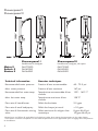
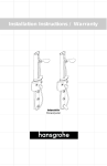
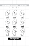
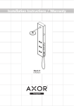
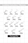
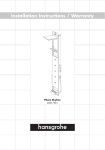
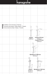
Installation Instructions / Warranty
Showerpanel I
Showerpanel II
Showerpanel I
Showerpanel II
Metro E
Solaris E
Stratos E
Showerpanel I
Showerpanel II
handshower & bodyjets
handshower, bodyjets, tub spout
06572000
06549XX0
06564XX0
06573000
06550XX0
06565XX0
Technical information
Données techniques
Recommended water pressure
Pression d’eau recommandée
45 - 72.5 psi
Max. water pressure
Pression d’eau maximum
147 psi
Recommended hot water temp.
Température recommandée d'eau
chaude
120� - 140� F*
Max. hot water temp
Température maximum d'eau
chaude
158�F*
Flow rate of handshower
Débit de douchette
2.5 gpm
Flow rate of each bodyspray
Débit de chaque jet mural
<1.0 gpm
Flow rate of thermostatic mixing
valve
Débit maximum du mitigeur thermostatique
8 gpm @ 45 psi
10 gpm @ 65 psi
*Please know and follow all applicable local plumbing codes when setting the temperature on the water heater.
* Vous devez connaître et respecter tous les codes de plomberie locaux applicables pour le réglage de la température
du chauffe-eau.
English
Français – voir p. 17
Installation considerations
• For best results, Hansgrohe recommends that this unit be installed by a
licensed, professional plumber.
• Protection against backflow provided
by check valve in the handshower
outlet.
• Please read over these instructions
thoroughly before beginning installation. Make sure that you have all tools
and supplies needed to complete the
installation.
• The high temperature limit stop on the
thermostatic mixing valve may be reset
to comply with local plumbing codes*
-- see page 13.
• This product is listed by IAPMO and is
approved for use in Massachusetts.
*In Massachusetts, the maximum output temperature
cannot exceed 112°F.
Tools required
The following tools are suggested for installing the showerpanel:
• Tape measure
• 3 mm Allen wrench
• Level
• Philips screwdriver
• Grease pencil or other marking device
• Waterproof sealant
• Drill with 6 mm bit suitable for wall
surface
• Mallet (to install anchors)
• 10 mm nut driver
• Teflon tape
• 10, 11 and 19 mm wrenches
Check package contents
Before beginning installation, check the contents of this package. Make sure that all parts
are present and in good condition. If any part is missing or damaged, please contact
Hansgrohe Customer Service before proceeding.
English
Rough-in
This unit can be installed on a flat wall or
in a 90° corner. Instructions for installation on a flat wall begin on page 5. Go
to page 8 if the panel is to be installed in
a corner.
Ensure that you have a minimum
83" ceiling height from the standing surface.
Stub out 1/2" NPT male nipples for the
hot and cold water supplies at the locations shown on the appropriate rough-in
Installation on a flat wall
diagram. The nipples should extend 5/8"
outside the surface of the finished wall.
Install the wall surface and make the wall
watertight before installing the panel. The
panel hangs on the finished wall.
Seal the wall around the
nipples with waterproof
sealant.
Failure to seal the wall
can lead to possible water
damage.
Installation in 90° corner
English
Installation � flat wall
Wrap the threads on the nipples with Teflon tape.
Install the elbows so that the outlets face upwards.
Measure up the wall 78 ¾", making sure that the line is
plumb. Mark the position for the top screw hole.
From the position of the top screw hole, measure down
35 3/8”. Mark the position for the center screw hole.
From the center screw hole, measure down 19 1/8".
Mark the position for the bottom screw hole.
Use a 6 mm bit to drill the three screw holes.
Seal the wall around the anchors
with waterproof sealant.
Failure to seal the wall can lead to
possible water damage.
Install the set screws in the top and bottom holes.
Use a 10 mm nut driver to attach a nut to the top set
screw.
Slide the panel over the top and bottom set screws.
Tighten the nut on the top set screw.
Install and tighten the nut on the bottom set screw.
Install one recessed head screw and the large washer
on the center hole. Tighten the screw.
English
Use the compression nuts and ferrules to connect
the supply hoses on the panel to the supply
elbows.
Use two wrenches, as shown, to prevent the supply hoses from twisting.
Attach the seals to the side covers.
Install the side covers.
The pins on the covers must go into the grooves on
the sides of the panel.
English
Push the bodyjet supply hose on the valve cover into the fitting on the panel.
Install the valve cover on the panel.
The pins on the cover must connect to the slots on the panel.
Turn to page 11 to continue the installation.
English
Installation in 90° corner
Wrap the threads on the nipples with Teflon tape.
Install the elbows so that the outlets face upwards.
In the corner, measure up the wall 78 ¾", making
sure that the line is plumb. Mark the position for the
top mounting bracket.
From the position of the top screw hole, measure
down 35 3/8". Mark the position for the center
mounting bracket.
From the center screw hole, measure down 19 1/8".
Mark the position for the bottom mounting bracket.
Use the mounting brackets as templates to mark the
positions of the screw holes. Drill the holes with a 6
mm bit.
Seal the wall around the anchors
with waterproof sealant.
Failure to seal the wall can lead to
possible water damage.
Install the mounting brackets to the walls using five of
the recessed head screws.
Install the corner sealing gasket to the grooves on
the panel.
English
While a helper holds the panel, attach the supply
hoses to the elbows with the compression fittings.
Use two wrenches, as shown in the diagram, to
prevent the supply hoses from twisting.
Tighten the hex head cap screw on the top
mounting bracket.
Install and tighten the hex head cap screw on the
bottom mounting bracket through the hole in the
panel and tighten.
Install the hex head cap screw and large washer
on the center mounting bracket through the hole
in the panel and tighten.
English
Clip the side cover seals as shown in the diagram. Attach the side cover seals to the valve
cover.
Push the bodyjet supply hose on the
valve cover into the fitting on the
panel.
Install the valve cover on the panel. The pins on the cover
must connect to the slots on the panel.
Turn to page 11 to continue the installation.
10
English
Install the handle
Push the handle over the valve stem. Tighten the handle
screw using a 3 mm Allen wrench.
The handle screw must engage the slot milled into the
cartridge.
Install the handshower
Place a black rubber washer one end of the hose. Connect
this end to the handshower outlet on the panel.
Place the screen washer in the other end of the hose.
Connect it to the handshower.
Place the handshower in the handshower holder.
Adjust the slider
Use a 2.5 mm Allen wrench to adjust the tension on the
slider.
Turn the screw clockwise to make the slider easier to move.
Turn the screw counter-clockwise to make the slider harder
to move.
11
English
Justify the handle
Turn the water on to the
handshower.
Turn the temperature control
knob until the output water is
100ºF. Turn the water off.
Turn the temperature control
knob so that the indicator is
next to the 100º marking.
Install the handle. Tighten
the screw.
12
Remove the handle.
English
Set the high temperature limit stop (optional)
Loosen the handle screw using a 3mm Allen wrench.
Remove the handle.
Remove the clip and the stop
ring from the stem.
Grasp the cartridge stop unit
and turn it counter-clockwise
to turn on the handshower.
Turn the stem until the output water is the desired maximum
high temperature (usually about 110°F*).
Turn the stop unit clockwise
to turn the water off.
Install the stop ring so that the
tooth is against the stop on the
top of the cartridge. Replace
the clip.
*In Massachusetts, the maximum output temperature cannot exceed 112°F.
Install the handle. Tighten
the screw.
13
English
User instructions - Showerpanel I
Turn the temperature control knob clockwise to make the water cooler, counter-clockwise to make it warmer. The
knob will stop at the 100°F position. If
water hotter than 100°F is desired, push
in on the knob, and continue turning it
counter-clockwise.
From the “off” position, turn the diverter handle counter-clockwise for the
handshower.
Turn the diverter handle clockwise for
the bodysprays. Turn the handle further
clockwise for the handshower and the
bodysprays simultaneously.
off position
temperature control knob
diverter handle
User instructions - Showerpanel II
Turn the temperature control knob clockwise to make the water cooler, counter-clockwise to make it warmer. The
knob will stop at the 100°F position. If
water hotter than 100°F is desired, push
in on the knob, and continue turning it
counter-clockwise.
From the “off” position, turn the diverter
handle counter-clockwise for the tub spout.
Turn the diverter handle clockwise for the
handshower, then for the handshower and
bodysprays simultaneously, and finally for
the bodysprays.
Using the handshower
The handshower has 3 spray modes -Rain AIR, Whirl AIR, and Balance AIR.
Push the function lever until the desired
spray mode is achieved.
14
function lever
English
Scale removal
The Raindance Air 3-jet handshower incorporates the Quick
Clean™ cleaning system. If scale deposits are noticed in the
spray channels, turn the water on lightly and rub the spray
channels with a finger or a sponge.
If scale deposits are noticed on the spray face, pour about
3/4” of a commercial scale remover, such as Lime-Away™ or
CLR™ ,into a shallow dish. Dilute the remover according to the
label instructions.
Soak only the spray face in the solution for the amount of time
specified on the label.
Rinse the handshower with clear water.
Install the handshower.
Flush the handshower with clear water for at least one
minute.
15
English
Check valve maintenance
The check valve should be removed and
inspected yearly.
If the check valve is damaged, replace it.
check valve
Clean the cartridge filters
If the water pressure decreases as the water is made
warmer, clean the cartridge filters.
Turn the water off at the main.
Remove the handle.
Hold the cartridge stop unit steady with a 36 mm
wrench.
Hold the stop unit steady while
removing or installing the thermostat cartridge.
Failure to do so may result in
damage to the stop unit.
Use a 24 mm wrench to unscrew the thermostatic
cartridge from the stop unit.
Clean the filters under running water. Use a soft toothbrush to remove stubborn deposits.
Lightly lubricate the cartridge o-rings with white
plumbers grease.
Install the thermostat cartridge.
Justify and install the handle.
16
filters
Français
À prendre en considération pour l’installation
• Pour de meilleurs résultats, Hansgrohe
recommande que ce produit soit
installé par un plombier professionnel
licencié.
• Veuillez lire attentivement ces instructions avant de procéder à l’installation.
Assurez-vous de disposer de tous les
outils et du matériel nécessaires pour
l’installation.
• Homologué par IAPMO.
• Le clapet anti-retour de la sortie de
douchette protège contre les retours
d'eau.
• La butée limite d'eau chaude de la
cartouche du mitigeur thermostatique
peur être reprogrammée pour satisfaire
aux codes de plomberie locaux -- voir
page 27.
Outils requis
Nous recommandons d’utiliser les outils suivants pour installer la colonne de douche :
• Ruban à mesurer
• Clé hexagonale de 3 mm
• Niveau
• Tournevis Phillips
• Crayon gras ou autre instrument de
marquage
• Agent d’étanchéité
• Perceuse avec une mèche de 6 mm
convenant à la surface du mur
• Maillet (pour installer les chevilles)
• Ruban de plomberie Téflon
• Tournevis à douille de 10 mm
• Clés de 10, 11 et 19 mm
Vérification du contenu de l’emballage
Épargnez du temps et évitez les problèmes. Vérifiez le contenu de cet emballage avant de
commencer l’installation. Assurez-vous qu’aucune pièce ne manque et qu’elles sont toutes
en bon état. S’il manque une pièce ou si une pièce est endommagée, veuillez contacter le
Service à la clientèle Hansgrohe avant de commencer l’installation.
17
Français
Pièce intérieure
Cet article peut être installé sur un mur à
plat ou dans un coin à angle de 90°. Les
instructions d’installation sur un mur plat
commencent à la page 19. Passez à la
page 22 si vous installez la colonne de
douche dans un coin.
Assurez-vous d’avoir une hauteur
de 83 po minimum (2,11 m), de
la surface du plancher jusqu’au
plafond.
Pour les conduites d’alimentation en eau
chaude et froide, faites sortir les mamelons
mâles NPT de ½ po aux emplacements
indiqués sur le schéma de pièce intéri-
Installation – mur plat
18
eure approprié. Les mamelons devraient
dépasser de 5/8 po (1,6 cm) de la surface
du mur fini.
Installez la surface de mur et assurez-vous
de son étanchéité avant d’installer la colonne. La colonne se suspend au mur fini.
Scellez le mur autour du
mamelon à l’aide d’un agent
d’étanchéité.
Si le mur n’est pas scellé, l’eau
pourrait éventuellement causer
des dommages.
Installation dans un coin à
angle de 90°
Français
Installation – mur plat
Enveloppez les filets des mamelons de conduite avec
du ruban de plomberie Téflon.
Installez les coudes (compris) de façon à ce que les
orifices de sortie soient dirigés vers le haut.
Mesurez le mur de bas en haut sur une longueur de
78 ¾ po en vous assurant que la ligne est droite, de
niveau. Marquez la position du trou de la vis du haut.
À partir du trou de la vis du haut, mesurez une longueur de 35 3/8 po vers le bas. Marquez la position
du trou pour la vis du centre.
À partir du trou de la vis du centre, mesurez 19 1/8
po vers le bas. Marquez la position du trou pour la
vis du bas.
Utilisez une mèche de 6 mm convenant à la surface du
mur. Percez les trois trous de vis.
Installez les chevilles.
Scellez le mur autour des
chevilles à l’aide d’un agent
d’étanchéité.
Si le mur n’est pas scellé, l’eau
pourrait éventuellement causer
des dommages.
Installez les vis de pression dans les trous du haut et
du bas.
Utilisez un tournevis à douille de 10 mm pour fixer un
écrou à la vis de pression du haut.
Faites glisser la colonne sur les vis de pression du haut
et du bas.
Serrez l’écrou sur la vis de pression du haut.
Installez et serrez l’écrou sur la vis de pression du
bas.
Installez une vis à tête fraisée et la grande rondelle
dans le trou du centre. Serrez la vis.
19
Français
Utilisez les écrous à compression et les
bagues d’extrémité pour relier les tuyaux
d’alimentation de la colonne aux coudes
d’alimentation.
Utilisez deux clés, tel qu’illustré, pour éviter
que les tuyaux d’alimentation ne s’entortillent.
Fixez les joints aux plaques latérales.
Installez les plaques latérales. Les tiges des plaques
doivent s’insérer dans les rainures sur les côtés de la
colonne.
20
Français
Poussez le conduit d’alimentation du jet mural sur le couvercle de la valve dans le raccord
de la colonne.
Installez le couvercle de la valve sur la colonne.
Les tiges du couvercle doivent se loger dans les fentes de la
colonne.
Passez à la page 25 pour continuer l’installation.
21
Français
Installation dans un coin à angle de
90°
Enveloppez les filets des mamelons avec du ruban
de plomberie Téflon. Installez les coudes (compris) de façon à ce que les orifices de sortie soient
dirigés vers le haut. Dans le coin, mesurez le mur
de bas en haut sur une longueur de 78 ¾ po en
vous assurant que la ligne est droite, de niveau.
Marquez la position du support de montage du
haut.
À partir du trou de la vis du haut, mesurez une
longueur de 35 3/8 po vers le bas. Marquez la
position du support de montage du centre.
À partir du trou de la vis du centre, mesurez 19
1/8 po vers le bas. Marquez la position du support de montage du bas.
Servez-vous des supports de montage comme
gabarit pour marquer la positions des trous de vis.
Percez les trous au moyen d’une mèche de 6 mm
convenant à la surface du mur.
Installez les chevilles.
Scellez le mur autour des
chevilles à l’aide d’un agent
d’étanchéité.
Si le mur n’est pas scellé, l’eau
pourrait éventuellement causer
des dommages.
Installez les supports de montage aux murs à l’aide
des cinq vis à tête fraisée.
Installez le joint d’étanchéité du coin sur les rainures
de la colonne.
22
Français
Demandez à quelqu’un de tenir la colonne, puis
fixez les tuyaux d’alimentation aux coudes à
l’aide des raccords à compression.
Utilisez deux clés, tel qu’illustré dans le schéma,
pour éviter que les tuyaux d’alimentation ne
s’entortillent.
Serrez la vis à tête hexagonale sur le support de
montage du haut.
Installez la vis à tête hexagonale dans le support
de montage du bas au travers du trou de la colonne et serrez-la.
Installez la vis à tête hexagonale et la grande
rondelle dans le support de montage du centre au
travers du trou de la colonne et serrez-la.
23
Français
Taillez les joints d’étanchéité de plaque latérale tel qu’illustré dans le schéma. Fixez les
joints de plaque latérale au couvercle de valve.
Poussez la conduite d’alimentation
du jet mural sur le couvercle de
la valve dans le raccord de la
colonne.
Installez le couvercle de la valve sur la colonne. Les
tiges du couvercle doivent se loger dans les fentes de la
colonne.
Passez à la page 25 pour continuer l’installation.
24
Français
Installation de la poignée
Poussez la poignée sur la tige de la valve. Serrez la
vis de pression au bas de la poignée à l’aide d’une
clé hexagonale de 3 mm. La vis de compression doit
s’engager dans la fente de l’élément thermostatique.
Installation de la douchette à main
Placez une rondelle en caoutchouc noir dans le raccord
de l’extrémité courte du tuyau. Vissez le raccord de
l’extrémité courte du tuyau à la sortie de la douchette sur
la colonne.
Placez le tamis dans le raccord de l’extrémité longue du
tuyau. Serrez le raccord de l’extrémité longue du tuyau
sur la douchette.
Placez la douchette dans son support.
Ajustement du curseur
Utilisez une clé hexagonale de 2,5 mm pour ajuster la
tension du curseur.
Tournez la vis dans le sens horaire pour que le curseur se
déplace facilement.
Tournez la vis dans le sens antihoraire pour que le curseur
se déplace moins facilement.
25
Français
Réglage de la poignée
Ouvrez la valve. Placez
le thermomètre dans le jet
d’eau.
Tournez le bouton de
contrôle de la température
jusqu’à ce que l’eau qui
s’écoule atteigne 100° F.
D’une main, tenez le levier
Installez la poignée. Serrez
de la poignée. Tourner le
la vis.
bouton de contrôle de la température jusqu’à ce qu’il soit
en position verticale et qu’il
atteigne l’arrêt de sûreté.
26
Fermez l’eau.
À l’aide d’une clé hexagonale de 3mm, desserrez la
vis de la poignée. Retirez la
poignée de la valve.
Français
Réglage de la butée limite d’eau chaude (en option)
Retirez l’étrier et la bague
de retenue de la tige de la
cartouche thermostatique.
À l’aide d’une clé hexagonale de 3mm, desserrez la
vis de la poignée.
Retirez la poignée de la
valve.
Tournez le dispositif d’arrêt
pour utiliser la douchette
Tournez la tige du mitigeur thermostatique jusqu’à ce que la
température de l’eau chaude atteigne le degré voulu – habituellement 110 °F* .
*Dans le Massachusetts, la température ne doit pas excéder 112°F.
Tournez le dispositif d'arrêt
au de la position «off».
Réinstallez la bague de
retenue de façon à ce qu’elle
s’appuie sur la butée d’arrêt.
Réinstallez l’étrier.
Réglez et réinstallez la
poignée.
27
Français
Instructions à l’intention de l’utilisateur – Showerpanel I
Tournez le bouton de contrôle de la
température dans le sens horaire pour
que l’eau soit plus froide, et dans le sens
antihoraire pour qu’elle soit plus chaude.
Le bouton de contrôle s’arrête à la position
de 100°F). Si vous désirez que la température de l’eau excède 100° F, poussez
sur le bouton de contrôle et continuez à le
tourner dans le sens antihoraire.
Depuis la position d’arrêt (« off »), tournez
la poignée de l’inverseur dans le sens
antihoraire pour utiliser la douchette.
Pour utiliser les jets muraux, tournez la poignée de l’inverseur dans le sens horaire.
Tournez la poignée plus loin encore dans
le sens horaire pour utiliser à la fois la
douchette et les jets muraux.
«off»
bouton de contrôle
poignée de
l'inverseur
Instructions à l’intention de l’utilisateur – Showerpanel II
Tournez le bouton de contrôle de la
température dans le sens horaire pour
que l’eau soit plus froide, et dans le sens
antihoraire pour qu’elle soit plus chaude.
Le bouton de contrôle s’arrête à la position
de 100°F. Si vous désirez que la température de l’eau excède 100°F, poussez
sur le bouton de contrôle et continuez à le
tourner dans le sens antihoraire.
Depuis la position d’arrêt (« off »), tournez
la poignée de l’inverseur dans le sens antihoraire pour utiliser le bec de la baignoire.
Tournez la poignée de l’inverseur dans le
sens horaire pour utiliser la douchette, puis
un peu plus loin pour la douchette et les
jets muraux simultanément, puis plus loin
pour les jets muraux uniquement.
Utilisation de la douchette
La douchette offre 3 modes de jet – « Rain AIR
», jet de pluie, « Whirl AIR », jet massant et «
Balance AIR », combinaison des deux jets.
Poussez le levier de fonctions jusqu’à ce que
vous obteniez le mode de jet voulu.
28
levier de fonctions
Français
Nettoyage
La douche à main Raindance Air 3-jet comprend le système nettoyant Quick Clean™ . Si vous remarquez que les
canaux de jet sont entartrés, ouvrez l’eau à faible débit et
frottez les canaux à l’aide d’une éponge ou avec un doigt
pour en déloger les dépôts.
En cas d’entartrage de la face des jets, versez environ
2 cm (¾ po) d’un détartrant commercial (comme LimeAway™ ou CLR™) dans un contenant peu profond.
Diluez le détartrant tel qu’indiqué sur les instructions de
l’étiquette.
Faites tremper seulement la face des jets dans cette solutions pour la période de temps spécifiée sur l’étiquette.
Rincez la douchette à l’eau claire.
Réinstallez la douchette. Ouvrez l’eau et faites fonctionner
la douchette durant au moins une minute.
29
Français
Entretien du clapet anti-retour
Le clapet anti-retour doit être retiré et examiné une
fois par année.
Le clapet anti-retour doit être remplacé s’il est
endommagé.
Entretien: nettoyage des tamis de
filtre
ATTENTION : Avant de commencer, fermez
l’eau à la vanne principale.
Retirez la poignée.
À l’aide d’une clé à molette, saisissez le pan de
manoeuvre sur le dispositif d’arrêt.
Tenez fermement le dispositif d’arrêt en place. À
l’aide d’une seconde clé à molette ou d’une clé à
douille longue de 17 mm, dévissez la cartouche
thermostatique et retirez-la.
ATTENTION : Le dispositif d’arrêt
pourrait être endommagé si vous ne
le retenez pas fermement en place lorsque
vous retirez ou remplacez la cartouche
thermostatique.
Rincez les débris ou dépôts pouvant se trouver dans
les tamis de filtre. Au besoin, brossez délicatement
à l’aide d’une brosse à dent douce. Ne retirez pas
les tamis.
Lubrifiez les joints toriques avec de la graisse blanche de plomberie. Tenez fermement le dispositif
d’arrêt en place. Réinstallez et serrez la cartouche
thermostatique.
Réglez et installez la poignée.
30
Replacement parts
1
1
12
11
18
2
18
2
13
3
7
7
6
5
11
3
17
14
4
4
10
15
19
15
19
8
10
5
9
16
20
1
2
3
4
5
6
7
8
9
10
11
slider
97024000
hose28276XX0
shelf
25969000
sleeve
88520XX0
thermostat cartridge
94282000
stop unit -- panel I25973000
side cover25974880
valve cover, panel I25976880
valve cover, panel II25985880
escutcheon25981XX0
handshower
Solaris E28518XX1
Stratos E28507XX1
Metro E28502XX1
12
13
14
15
16
17
18
19
20
handle - Solaris E
handle - Stratos E
handle - Metro E
check valve
tub spout (panel II only)
cartridge (panel II only)
screen washer
hose washer
hardware kit
88530XX0
88547XX0
88548XX0
94074000
88584XX0
88500000
94246000
98058000
25977001
XX = finish
00 = chrome
82 = brushed nickel
31
Cleaning Recommendation for Hansgrohe Products
Modern lavatory faucets, kitchen faucets, and showers consist of very different materials to comply with the needs of
the market with regard to design and functionality. To avoid damage and returns, it is necessary to consider certain
criteria when cleaning.
Cleaning Materials for Faucets and Showers
Acids are a necessary ingredient of cleaning materials for removing lime, however please pay attention to the following points when cleaning faucets and showers:
•
Only use cleaning materials which are explicitly intended for this type of application.
•
Never use cleaning materials which contain hydrochloric, formic, phosphoric, or acetic acid, as they cause
considerable damage.
•
Never mix one cleaning material with another.
•
Never use cleaning materials or appliances with an abrasive effect, such as unsuitable cleaning powders, sponge
pads, or micro fiber cloths.
Cleaning Instructions for Faucets and Showers
Please follow the cleaning material manufacturer’s instructions. In addition, pay attention to the following points:
•
Clean the faucets and showers as and when required
•
Use the amount of cleaning product and the amount of time recommended by the manufacturer. Do not leave the
cleaner on the fixture longer than necessary.
•
Regular cleaning can prevent calcification.
•
When using spray cleaners, spray first onto a soft cloth or sponge. Never spray directly onto the faucet as droplets can enter openings and gaps and cause damage.
•
After cleaning, rinse thoroughly with clean water to remove any cleaner residue.
Important
Residues of liquid soaps, shampoos, and shower foams can also cause damage, so rinse with clean water after using.
Please note: if the surface is already damaged, the effect of cleaning materials will cause further damage.
Components with damaged surfaces must be replaced or injury could result.
Damage caused by improper treatment is not covered under the warranty.
Recommandations pour le nettoyage des produits Hansgrohe
Les robinetteries modernes de lavabo, de cuisine et de douche utilisent des matériaux très différents pour répondre aux
besoins du marché en termes de conception et de fonctionnalité. Certaines règles de base doivent être respectées lors
du nettoyage de ces produits afin d’éviter de les endommager ou d’avoir à les retourner.
Produits de nettoyage pour robinetteries et douches
Les acides sont une partie intégrante nécessaire de tous les produits de détartrage; il faut cependant prendre les
précautions suivantes lors du nettoyage des robinets et des douches :
•
N’utilisez que des produits/articles de nettoyage conçus spécifiquement pour les articles de robinetterie et de
douche.
•
N’utilisez jamais de produits/articles de nettoyage contenant de l’acide chlorhydrique, formique, phosphorique
ou acétique car ils pourraient causer des dommages considérables.
•
Ne mélangez jamais deux produits de nettoyage.
•
N’utilisez jamais de produits/articles de nettoyage de nature abrasive tels que poudres de nettoyage, tamponséponge ou chiffons microfibre non appropriés.
32
Instructions de nettoyage pour robinetteries et douches
Veuillez suivre les instructions du fabricant de produits/articles de nettoyage. De plus, tenez compte des conseils
suivants :
Nettoyez vos produits de robinetterie et de douche aussi souvent que nécessaire.
•
Utilisez la quantité de produit nettoyant et respectez la durée recommandée par le fabricant. Ne laissez pas le
produit sur les articles de robinetterie plus longtemps que nécessaire.
•
Un nettoyage régulier peut prévenir la formation de dépôts calcaires.
•
Si vous utilisez des nettoyants en vaporisateur, vaporisez d’abord sur une éponge ou un chiffon. Ne vaporisez
jamais directement sur un robinet : des gouttelettes pourraient s’infiltrer dans les ouvertures et les interstices et
endommager celui-ci.
•
Après le nettoyage, rincez abondamment avec de l’eau propre pour éliminer tout résidu de produit nettoyant.
Important
Les résidus de savon liquide, de shampoing et de mousse pour la douche peuvent également endommager la robinetterie; rincez donc avec de l’eau propre après utilisation de ces produits.
Veuillez noter : si la surface est déjà endommagée, les produits de nettoyage l’endommageront encore plus.
Les composants dont la surface est endommagée devraient être remplacés sous peine d’entraîner
des blessures.
Les dommages dus à un mauvais traitement ne sont pas couverts par la garantie.
Limited Lifetime Consumer Warranty
This product has been manufactured and tested to the highest quality standards by Hansgrohe, Inc. (“Hansgrohe”).
This warranty is limited to Hansgrohe products which are purchased by a consumer in the United States after March 1,
1996, and installed in either the United States or Canada.
WHO IS COVERED BY THE WARRANTY
This warranty extends to the original consumer purchaser only. This warranty is non-transferable.
WHAT IS COVERED BY THE WARRANTY
This warranty covers only your Hansgrohe manufactured product. Hansgrohe warrants this product against defects in
material or workmanship as follows: Hansgrohe will repair at no charge for parts only or, at its option, replace any
product or part of the product that proves defective because of improper workmanship and/or material, under normal
installation, use, service and maintenance. If Hansgrohe is unable to provide a replacement and repair is not practical
or cannot be timely made, Hansgrohe may elect to refund the purchase price in exchange for the return of the product.
LENGTH OF WARRANTY
Replacement or repaired parts of products will be covered for the term of this warranty as stated in the following two
sentences. If you are a consumer who purchased the product for use primarily for personal, family, or household
purposes, this warranty extends for as long as you own the product and the home in which the product is originally
installed. If you purchased the product for use primarily for any other purpose, including, without limitation, a commercial purpose, this warranty extends only (i) for 1 year, with respect to Hansgrohe and Commercial products, and (ii) for
5 years, with respect to AXOR products.
THIS WARRANTY DOES NOT COVER, AND HANSGROHE WILL NOT PAY FOR:
A. Conditions, malfunctions or damage not resulting from defects in material or workmanship.
B. Conditions, malfunctions or damage resulting from (1) normal wear and tear, improper installation, improper
maintenance, misuse, abuse, negligence, accident or alteration, or (2) the use of abrasive or caustic cleaning
agents or “no-rinse” cleaning products, or the use of the product in any manner contrary to the product instructions. (3) Conditions in the home such as excessive water pressure or corrosion.
33
C. Labor or other expenses for the disconnection, deinstallation, or return of the product for warranty service, or for
installation or reinstallation of the product (including but not limited to proper packaging and shipping costs), or
for installation or reinstallation of the product.
D. Accessories, connected materials and products, or related products not manufactured by Hansgrohe.
TO OBTAIN WARRANTY PARTS OR INFORMATION
Contact your Hansgrohe retailer, or contact Technical Service at:
Hansgrohe Inc.
1492 Bluegrass Lakes Parkway
Alpharetta GA 30004
Toll-free (800) 334-0455.
In requesting warranty service, you will need to provide
1. The sales receipt or other evidence of the date and place of purchase.
2. A description of the problem.
3. Delivery of the product or the defective part, postage prepaid and carefully packed and insured, to Hansgrohe
Inc. 1492 Bluegrass Lakes Parkway, Alpharetta, Georgia 30004, Attention: Technical Service, if required by
Hansgrohe.
When warranty service is completed, any repaired or replacement product or part will be returned to you postage
prepaid.
EXCLUSIONS AND LIMITATIONS
REPAIR OR REPLACEMENT (OR, IN LIMITED CIRCUMSTANCES, REFUND OF THE PURCHASE PRICE) AS PROVIDED
UNDER THIS WARRANTY IS THE EXCLUSIVE REMEDY OF THE PURCHASER. HANSGROHE NEITHER ASSUMES
NOR AUTHORIZES ANY PERSON TO CREATE FOR IT ANY OBLIGATION OR LIABILITY IN CONNECTION WITH
THIS PRODUCT.
HANSGROHE SHALL NOT BE LIABLE TO PURCHASER OR ANY PERSON FOR ANY INCIDENTAL, SPECIAL, OR
CONSEQUENTIAL DAMAGES, ARISING OUT OF BREACH OF THIS WARRANTY OR ANY IMPLIED WARRANTY
(INCLUDING MERCHANTABILITY).
Some States do not allow the exclusion or limitation of incidental or consequential damages, so the above limitation
or exclusion may not apply to you. This warranty gives you specific legal rights, and you may have other rights which
vary from State to State. You may be required by law to give us a reasonable opportunity to correct or cure any failure
to comply before you can bring any action in court against us under the Magnuson-Moss Warranty Act.
PRODUCT INSTRUCTIONS AND QUESTIONS
Upon purchase or prior to installation, please carefully inspect your Hansgrohe product for any damage or visible
defect. Prior to installing, always carefully study the enclosed instructions on the proper installation and the care and
maintenance of the product. If you have questions at any time about the use, installation, or performance of your
Hansgrohe product, or this warranty, please call or write to us or call us toll-free at 800 334 0455.
34
35
www.hansgrohe-usa.com
US - Installation Instructions • Part No. 90972801-04 • Revised 7/2008
Hansgrohe, Inc. • 1490 Bluegrass Lakes Parkway • Alpharetta, GA 30004
Tel. 770-360-9880 • Fax 770-360-9887