1
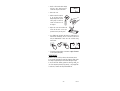
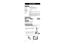
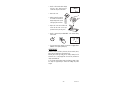
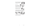
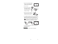
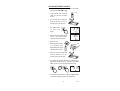
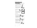
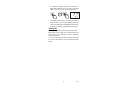
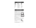
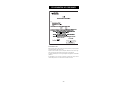
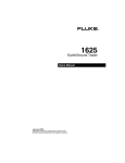
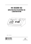
Instruction Manual
C 216 & C 226
Multiparameter Bench
Photometers
for
Pool & Spa Applications
These Instruments are in
Compliance with the CE Directives
www.hannainst.com
1
Dear Customer,
Thank you for choosing a Hanna product. Please read this instruction
manual carefully before using the meter. This manual will provide you
with the necessary information for the correct use of the instrument. If
you need additional technical information, do not hesitate to e-mail
us at [email protected]. These instruments are in compliance with
directives.
TABLE OF CONTENTS
CALCIUM HARDNESS ..................... 26
FREE CHLORINE ............................ 28
TOTAL CHLORINE .......................... 30
FREE COPPER ............................... 32
TOTAL COPPER .............................. 34
CYANURIC ACID ............................ 36
IRON ........................................... 38
OZONE ......................................... 40
pH ............................................... 44
INTERFACE WITH PC ..................... 46
STANDARD METHODS ................... 48
BATTERY REPLACEMENT ................ 48
ACCESSORIES ............................... 49
CE DECLARATION OF CONFORMITY .... 50
WARRANTY ................................... 51
HANNA LITERATURE ...................... 51
PRELIMINARY EXAMINATION ........... 3
GENERAL DESCRIPTION ................... 3
ABBREVIATIONS ............................. 4
SIGNIFICANCE OF POOL AND SPA
TESTING ......................................... 5
SPECIFICATIONS ........................... 10
PRECISION AND ACCURACY ............ 10
PRINCIPLE OF OPERATION ............. 11
FUNCTIONAL DESCRIPTION ............ 13
GUIDE TO DISPLAY CODES ............. 14
TIPS FOR AN ACCURATE
MEASUREMENT ............................ 17
PARAMETERS REFERENCE TABLES .. 19
OPERATIONAL GUIDE .................... 20
ALKALINITY ................................... 22
BROMINE ..................................... 24
All rights are reserved. Reproduction in whole or in part is prohibited without
the written consent of the copyright owner, Hanna Instruments Inc.,
Woonsocket, Rhode Island, 02895 , USA.
2
PRELIMINARY EXAMINATION
Please examine this product carefully. Make sure that the instrument
is not damaged. If any damage occured during shipment, please
notify your Dealer.
Each Meter is supplied complete with:
• Four Sample Cuvets and Caps
• Two 9V Batteries
• One pair of scissors
• Instruction Manual
• Rigid carrying case
Note: Save all packing material until you are sure that the instrument
works correctly. Any defective item must be returned in its
original packing with the supplied accessories.
3
GENERAL DESCRIPTION
C 99 & C 200 Series is a line of 17 different bench, microprocessorbased photometers to measure more than 50 different parameters in
water and wastewater. These multipurpose meters are manufactured
to measure the most important parameters of the application they
have been especially designed for:
C 99 Laboratories, with COD C 200 Laboratories
C 203 Aquaculture
C 205 Boilers & Cooling Towers
C 206 Environmental Testing
C 207 Industrial Wastewater
C 208 Water Conditioning
C 209 Education
C 210 Pulp & Paper Mills
C 211 Chemical Manufacturers
C 212 Power Plant Utilities
C 213 Municipal Wastewater
C 214 Wastewater Treatment Applic. C 215 Nutrient Analyses C 216
Pool & Spa Applic.
C 218 Environmental Applic.
C 226 Pool & Spa Applic.
All meters use an exclusive positive-locking system to ensure that the
cuvet is in the same position every time it is placed into the measurement
cell.
The reagents are in liquid or powder form and are supplied in bottles
or in packets. The amount of reagent is precisely dosed to ensure the
maximum repeatability.
Display codes aid the user in routine operations.
The meters have an auto-shut off feature that will turn off the
instrument after 10 minutes of non-use.
The C 99 & C 200 Series can be connected to a personal computer via
the HI 920010 three wire RS 232 cable. The HI 92000 Hanna
Windows® Compatible Software aids the user to manage all test data.
ABBREVIATIONS
°C:
degree Celsius
EPA:
US Environmental Protection Agency
°F:
degree Fahrenheit
g/L:
grams per liter. g/L is equivalent to ppt (part per
thoushand)
mg/L:
milligrams per liter. mg/L is equivalent to ppm (part per
million)
mL:
milliliter
µg/L:
micrograms per liter. µg/L is equivalent to ppb (part per
billion)
4
SIGNIFICANCE OF
POOL AND SPA TESTING
A major family leisure pursuit is the enjoyment of Swimming Pool and
Spa facilities world-wide. A basic necessity of Pool water treatment, to
ensure such enjoyment, is to maintain the water in a safe and pleasant
condition for the bathers.
In order to achieve such an objective, swimming pool water requires
testing on daily, and sometimes hourly bases for disinfection residuals
and pH. Equally important, Calcium Hardness and Alkalinity parameters
should be monitored on weekly bases to ensure the pool water is
maintained in a balanced condition, thus to avoid system failure because
of corrosion or scale formation.
DISINFECTION RESIDUAL AND pH CONTROL
In terms of swimming pool treatment, disinfection or sanitizing basically
means to rid the pool of bather pollution, destroy bacteria, and control
nuisance organisms like algae, which may occur in the pool, filtration
equipment, and piping.
There are a number of techniques used, namely, chlorine, bromine and
ozone dosing systems, of which chlorine is the most common.
Chlorine
Chlorine is a strong oxidizing agent that destroys mostly organic pollutants,
bacteria and can combine with nitrogen containing compounds, forming
chloramines. Only a part of the original quantity dosed chlorine, remains
active and continues its disinfecting action.
From the free chlorine you can distinguish combined chlorine, as that
part which combines with nitrogen containing compound and that is less
efficient as a disinfectant. The addition of these two parts gives total
chlorine. A pool manager needs to aim perfection where free equals
total chlorine, and thus to maintain the combined chlorine concentration
near zero. The presence of chloramines is not desired because of the
distinctive ‘swimming pool’ smell caused by combined chlorines like dichloramines. Beside this unpleasant odour it does irritate the eyes and
the mucous membranes.
Commercially chlorine for disinfection may be available as a gas (Cl2), a
liquid like sodium hypochlorite or bleach (NaOCl) or in a solid state like
calcium hypochlorite, chloro-hydantoins or chloro-cyanuric acid
compounds.
These compounds, once dissolved in water do establish equilibrium
5
between the hypochlorous acid (HOCl) and the hypochlorite ions (OCl-).
Although both forms are considered free chlorine, it is the hypochlorous
acid that provides the strongest disinfecting and oxidising characteristic
of chlorine solutions.
The amount of hypochlorous acid in chlorinated water dependends upon
the pH value of the solution. Changes in pH value will effect the HOCl
equilibrium in relation to the hydrogen and hypochlorite ion.
As depicted by the curve below, HOCl decreases and OCl- increases as pH
increases. At a low pH, almost all the free chlorine is in the molecular
form HOCl and at a pH of around 7.5, the ratio between HOCl and OCl- is
50:50. Since the ionic form OCl- is a slow acting sanitizer while the
molecular HOCl is a fast acting, it is important to measure regularly the
pH. As a general rule a pH of about 7.2 is recommended to maintain fast
acting disinfection conditions.
Bromine
In many countries bromine sanitizing has been introduced as an
alternative for chlorine, although it is a less strong sanitizer. The advantage
of bromine is its stability at higher temperatures (advantageous for hot
well pools), and its maintained disinfection power at higher pH. Further
it does hardly react with nitrogen compounds, reducing the unpleasant
odour, and eye irritation problems. The main disadvantage of bromine is
the slower acting disinfecting power, making it less suitable for larger
pools.
Ozone
Ozone is a very strong oxidizing agent that does destroy most difficult to
oxidize organic compounds and chloramines. It thus allows the pool
manager to remove very efficiently combined chlorine without refreshing
6
frequently large amounts of pool water. In general its application is found
just before water passes through the filter units. Its sanitizing power is
not pH related.
Mainly because of its strong oxidizing power the return water may contain
only trace concentrations of ozone. It has to be mentioned that ozone is
very unstable and there is anyway the need for low-level chlorination to
ensure sanitizing throughout the whole pool.
THE WATER BALANCE AND LANGELIER INDEX (LI)
The pool water characteristics need to be maintained in a balanced
condition to avoid system failure. Measuring the water balance is
extremely important to predict if the water is corrosive, scaling or balanced.
A saturation index developed by Dr. Wilfred Langelier is widely used to
predict the balance of swimming pool waters. It is an estimation of the
solutions ability to dissolve or precipitate calcium carbonate deposits. A
certain level of this precipitation (filming) is desired to insulate pipes
and boilers from contact with water. When no protective filming is formed,
water is considered to be corrosive. On the other hand scaling does cause
failure because of incrustation problems.
In the treatment and monitoring of pool water, the pool manager must
ensure that related parameters as alkalinity, hardness and pH are duly
taken into consideration.
Calcium Hardness
The presents of calcium in the system is desired to ensure filming on
those places where the temperature is relatively high, like in boilers and
pipes transporting warm water. Scaling must be avoided because it
reduces heat transfer and pump capacity. Beside the calcium carbonate
deposits in the pipes, high scaling values do cause cloudy water.
It is recommended to maintain the calcium hardness value within the
range from 200 to 400 ppm as calcium carbonate (CaCO3).
Alkalinity
Alkalinity is the measure of the total concentration of alkaline substances,
mostly bicarbonates, dissolved in the water. The higher the alkalinity the
more resistant the water is to pH change, the alkalinity buffers the water.
At the same time, high alkaline water is a major contributor to scaling
problems like incrustation in filtration equipment, pumps, and piping.
It is recommended to maintain the alkalinity value within the range
from 80 to 125 ppm as calcium carbonate (CaCO3).
pH
The pH of the water is an important factor since at lower pH the corrosion
7
rate increases. If the alkalinity values are sufficiently high it will not be
difficult to control the pH. Most pools managers do prefer to keep the pH
between 7.2 and 7.4, that does ensure low corrosion rates and a sufficient
activity of chlorine.
Langelier Index (LI)
The Langelier Index is a powerful tool to calculate the water balance,
and to predict corrosion or scaling problems. Theoretically, a LI of zero
indicates perfect water condition for swimming pools. If LI>0, scaling
and staining of the water is present, and if LI<0 the water is corrosive
and highly irritating. A tolerance of ±0.4 is normally acceptable.
The Langelier formula is expressed as:
LI = pH + TF + HF + AF – 12.5
where:
LI = Langelier Index (also called Saturation Index)
pH = pH of the water
TF = temperature factor
HF = hardness factor, log(Ca Hardness, ppm as CaCO3)
AF = alkalinity factor, log(Alkalinity, ppm as CaCO3)
To calculate the exact Langelier Index of your water please use the WATER
INDEX reference tables at the end of this chapter to find the Temperature,
Hardness and Alkalinity factors.
Recommendations
For most pools, water is balanced if:
• The pH value is maintained within the recommended ranges of
pH 7.2 - 7.6
• Ideally the Alkalinity should be maintained within a range of
80 - 125 ppm
• The Calcium Hardness should be maintained within a range of
200 - 400 ppm.
To calculate your water balance three tests are required, measure the
Calcium Hardness, the Alkalinity and the pH of the pool water. Find the
Hardness and Alkalinity Factor in the WATER INDEX reference tables
below.
The water temperature is in general controlled between 24oC (76oF) and
34oC (94oF) to ensure pleasant bather comfort. The Temperature Factor
in this temperature range has minor importance; therefore an average
value of 0.7 may be used..
A simple calculation classifies your water in corrosive, scaling, acceptable
or ideal balanced, with treatment recommendations:
Water Balance = pH + TF + HF + AF
8
Water Balance Condition of Water
11.0 – 12.0
12.1 – 12.3
12.4 – 12.6
12.7 – 12.9
13.0 – 14.0
Recommendation
Corrosive
Increase pH and/or Alkalinity
Acceptable Balance
Retest water frequently
Ideal Balance
Acceptable Balance
Retest water frequently
Scale forming
Reduce pH and/or alkalinity
WATER INDEX REFERENCE TABLES
Temperature
TF
°C °F
0
4
8
12
16
20
24
28
32
36
40
50
32
39
46
54
60
68
75
82
90
97
104
122
Calcium Hardness
mg/L
HF
(as CaCO3)
0
0.1
0.2
0.3
0.4
0.5
0.6
0.7
0.7
0.8
0.9
1.0
5
25
50
75
100
150
200
250
300
400
500
1000
Alkalinity
mg/L
AF
(as CaCO3)
0.7
1.4
1.7
1.9
2.0
2.2
2.3
2.4
2.5
2.6
2.7
3.0
5
25
50
75
100
150
200
250
300
400
500
1000
0.7
1.4
1.7
1.9
2.0
2.2
2.3
2.4
2.5
2.6
2.7
3.0
EXAMPLE:
Pool water conditions
Factor value
(nearest values)
Temperature
30°C
TF = 0.7
pH
7.2
pH = 7.2
Alkalinity
80 mg/L
AF = 1.9
Hardness
230 mg/L
HF = 2.4
Water Balance = pH + TF + HF + AF
= 7.2 + 0.7 + 2.4 + 1.9 = 12.2
Conclusion: the water is acceptable balanced but there is some risk
that the water becomes corrosive; frequently testing is recommended.
The Hanna C216 and C226 are the ideal instruments to meet your
monitoring requirements….
9
SPECIFICATIONS
Life of the instrument
Silicon Photocell
0 to 50°C (32 to 122°F);
max 90% RH non-condensing
Power Supply
2 x 9 V batteries / 12 to 20 VDC through
voltage adapter (optional)
Auto-Shut off
After 10' of non-use
Dimensions
230 x 165 x 70 mm (9.0 x 6.5 x 2.8")
Weight
640 g (22.6 oz.)
For specifications related to each single parameter (e.g. range, precision,
etc.), refer to the related measurement section.
Light Life
Light Detector
Environment
PRECISION AND ACCURACY
Precision is how closely repeated measurements agree with each other.
Precision is usually expressed as standard deviation (SD).
Accuracy is defined as the nearness of a test result to the true value.
Although good precision suggests good accuracy, precise results can be
inaccurate. The figure explains these definitions.
For each parameter, the precision is expressed in the related measurement
section as standard deviation at a specific concentration value of the
analite. The standard deviation is obtained with a single instrument using
a representative lot of reagent.
10
PRINCIPLE OF OPERATION
Absorption of Light is a typical phenomenon of interaction between
electromagnetic radiation and matter. When a light beam crosses a
substance, some of the radiation may be absorbed by atoms, molecules
or crystal lattices.
If pure absorption occurs, the fraction of light absorbed depends both
on the optical path length through the matter and on the physicalchemical characteristics of substance according to the Lambert-Beer
Law:
-log I/Io = ελ c d
or
A = ελ c d
Where:
-log I/Io=Absorbance (A)
Io =intensity of incident light beam
I =intensity of light beam after absorption
ελ =molar extinction coefficient at wavelength λ
c =molar concentration of the substance
d =optical path through the substance
Therefore, the concentration "c" can be calculated from the absorbance
of the substance as the other factors are known.
Photometric chemical analysis is based on the possibility to develop
an absorbing compound from a specific chemical reaction between
sample and reagents.
Given that the absorption of a compound strictly depends on the
wavelength of the incident light beam, a narrow spectral bandwidth
should be selected as well as a proper central wavelength to optimize
measurements.
The optical system of Hanna's C 99 & C 200 Series multiparameter
photometers is based on special subminiature tungsten lamps and
narrow-band interference filters to guarantee both high performance
and reliable results.
Four measuring channels (at four different wavelengths) allow a wide
range of tests.
C 200 Series block diagram (optical layout)
11
A microprocessor controlled special tungsten lamp emits radiation
which is first optically conditioned and beamed to the sample contained
in the cuvet. The optical path is fixed by the diameter of the cuvet.
Then the light is spectrally filtered to a narrow spectral bandwidth, to
obtain a light beam of intensity Io or I.
The photoelectric cell collects the radiation I that is not absorbed by
the sample and converts it into an electric current, producing a
potential in the mV range.
The microprocessor uses this potential to convert the incoming value
into the desired measuring unit and to display it on the LCD.
The measurement process is carried out in two phases: first the meter
is zeroed and then the actual measurement is performed.
The cuvet has a very important role because it is an optical element
and thus requires particular attention. It is important that both the
measurement and the calibration (zeroing) cuvets are optically identical
to provide the same measurement conditions. Whenever possible use
the same cuvet for both.
It is necessary that the surface of the cuvet is clean and not scratched.
This is to avoid measurement interference due to unwanted reflection
and absorption of light. It is recommended not to touch the cuvet
walls with hands.
Furthermore, in order to maintain the same conditions during the
zeroing and the measuring phases, it is necessary to close the cuvet to
prevent any contamination.
12
FUNCTIONAL DESCRIPTION
FRONT PANEL
1)
2)
3)
4)
5)
Cuvet Holder
Dual Level Liquid Crystal Display (LCD)
Programs List
READ DIRECT, to perform measurement immediately
TIMER, to perform measurement after a preprogrammed
countdown
6) ZERO, to zero the meter prior to measurement
7) Program ▼ and ▲, to select the desired parameter
8) ON/OFF, to turn the meter on and off
REAR PANEL
1) Power Supply 12 VDC 2.5 Watt
2) RS 232 Socket
3) Batteries Compartment
13
GUIDE TO DISPLAY CODES
Note: The secondary LCD below shows a generic "P– –", whereas the
meter will indicate the exact program number (e.g. in C 216, "P1"
for Alkalinity).
This indicates that the meter is in a ready
state and zeroing can be performed.
Sampling in progress. This flashing prompt
appears each time the meter is performing
a measurement.
The microprocessor is adjusting the light
level, indicated by a scrolling "SIP".
This indicates that the meter is in a zeroed
state and measurement can be performed.
The instrument is performing an internal
check-up.
The blinking "LOBAT" indicates that the
battery voltage is getting low and the
batteries need to be replaced.
This indicates that the batteries are dead
and must be replaced.
Light over range. The cuvet is not inserted
correctly and an eccess ambient light is
reaching the detector. If the cuvet is properly
inserted, then contact your dealer or the
nearest Hanna Customer Service Center.
14
The lamp is not working properly. Contact
your dealer or the nearest Hanna Customer
Service Center.
The lamp is not working properly. Contact
your dealer or the nearest Hanna Customer
Service Center.
This indicates that the meter has lost its
configuration. Contact your dealer or the
nearest Hanna Customer Service Center.
ERROR MESSAGES
a) on zero reading:
This indicates that the zeroing procedure
failed due to a low signal-to-noise ratio. In
this case press ZERO again.
The instrument cannot adjust the light level.
Please check that the sample does not
contain any debris.
There is not enough light to perform a
measurement. Please check the preparation
of the zero cuvet.
There is too much light to perform a
measurement. Please check the preparation
of the zero cuvet.
b) on sample reading:
There is too much light for the sample
measurement. Please check if the right
sample cuvet is inserted.
The sample and zero cuvet are inverted.
15
A zero reading was not taken. Follow the
instruction described in the measurement
procedures for zeroing the meter.
Under range. A blinking "0.00" indicates
that the sample absorbs less light than the
zero reference. Check the procedure and
make sure that you use the same cuvet for
reference (zero) and measurement.
1) A flashing value of the maximum
concentration indicates an over range
condition. The concentration of the sample
is beyond the programmed range: dilute
the sample and rerun the test.
2) A flashing value lower than the
maximum concentration indicates a low
signal-to-noise ratio condition. In this case
accuracy of the result is not guaranteed.
Repeat the reading procedure.
16
TIPS FOR AN ACCURATE MEASUREMENT
The instructions listed below should be carefully followed during testing
to ensure best accuracy.
• Color or suspended matter in large amounts may cause interference,
therefore, these should be removed by treatment with active
carbon and by prior filtration.
• For a correct filling of the cuvet: the liquid
in the cuvet forms a convexity on the top;
the bottom of this convexity must be at
the same level of the 10 mL mark.
10 mL
• Proper use of the dropper:
(a) to get good reproducible results, tap the dropper on the table
for several times and wipe the outside of the dropper tip with
a cloth.
(b) always keep the dropper bottle in a vertical position while
dosing the reagent.
(a)
(b)
• Proper use of the powder reagent packet:
(a) use scissors to open the powder packet;
(b) push the edges of the packet to form a spout;
(c) pour out the content of the packet.
(a)
(b)
(c)
• It is important that the sample does not contain any debris. This
would corrupt the reading.
17
• In order to avoid reagent leaking
and to obtain more accurate
measurements, it is recommended
to close the cuvet first with the
supplied HDPE plastic stopper and
then with the black cap.
• Each time the cuvet is used, the
cap must be tightened to the same
degree.
• Whenever the cuvet is placed into
the measurement cell, it must be
dry outside, and completely free of
fingerprints, oil or dirt. Wipe it
thoroughly with HI 731318 (tissue
for wiping cuvets, see chapter
ACCESSORIES) or a lint-free cloth
prior to insertion.
• Shaking the cuvet can generate bubbles in the sample, causing
higher readings. To obtain accurate measurements, remove such
bubbles by swirling or by gently tapping the vial.
• Do not let the reacted sample stand too long after reagent is
added, or accuracy will be lost.
• It is possible to take multiple readings in a row, but it is
recommended to take a new zero reading for each sample and to
use the same cuvet for zeroing and measurement.
• After the reading it is important to discard immediately the sample,
otherwise the glass might become permanently stained.
• All the reaction times reported in this manual are referred to 20°C
(68°F). As a general rule of thumb, they should be doubled at
10°C (50°F) and halved at 30°C (86°F).
18
PARAMETERS REFERENCE TABLES
C 216 - POOLMETER
C 226 - POOLMETER
Code Parameter
1 Alkalinity
Code Parameter
1 Alkalinity
Page
22
Page
22
2 Ca Hardness
3 Free Chlorine
26
28
2 Bromine
3 Ca Hardness
24
26
4 Total Chlorine
5 Cyanuric Acid
6 pH
30
36
44
4 Free Chlorine
5 Total Chlorine
6 Free Copper
28
30
32
7 Total Copper
8 Cyanuric Acid
34
36
9 Iron
10 Ozone
11 pH
19
38
40
44
OPERATIONAL GUIDE
POWER CONNECTION
Remove the battery cover on the back of the meter; attach 2 fresh 9V
batteries and replace the cover.
Alternatively, plug the optional 12VDC adapter (HI 710005 - 110VDC,
or HI 710006 - 220VDC) into the DC socket. Plug the adapter into the
outlet.
Note: Insure the main line is surge protected.
Note: Always turn the meter off before unplugging it to insure no data
is lost.
MEASUREMENT PROCEDURE
• Turn the meter on by pressing ON/OFF.
• The meter will first perform an LCD auto
diagnostic test by displaying a full set of
figures.
• Then it will show a scrolling
"c --- Hanna Inst", whereas
the meter will indicate the
exact meter code (C 216 or
C 226) .
• When the LCD displays “----”, the meter
is ready. On the secondary LCD "P1" will
appear to inform that the first parameter
measurement procedure (Alkalinity both
for C 216 and C 226) can be performed.
• Press the PROGRAM ▼ and PROGRAM ▲ keys to select the
desired parameter.
For the program number, see the parameters reference tables on
page 19 or look at the list printed on the mask of the meter.
20
• After the desired program number appears on the secondary
display, follow the measurement procedure described in the related
chapter.
• Select a new parameter measurement procedure by pressing the
PROGRAM ▼ and PROGRAM ▲ keys.
Note: in the following measurement
sections, a generic "P– –" will be placed
on the secondary LCD instead of the exact
related message (e.g. in C 226, "P2" for Bromine).
• Before performing a test read carefully all the instructions related
to the selected parameter.
21
ALKALINITY
SPECIFICATIONS
Range
Resolution
Precision
Typical EMC
Deviation
Light Source
Method
0 to 500 mg/L (as CaCO3)
5 mg/L
±10 @ 100 mg/L
±5 mg/L
Tungsten lamp with narrow band interference filter
@ 575 nm
Colorimetric Method. At different alkalinity levels
a distinctive range of colors from yellow to green
and greenish blue will develop.
REQUIRED REAGENTS
Code
HI 93755-0
Description
Alkalinity Indicator Reagent
Quantity/test
1 packet
REAGENT SETS
HI 93755-01 Reagents for 100 tests
HI 93755-03 Reagents for 300 tests
For other accessories see page 49.
MEASUREMENT PROCEDURE
• Select the program number corresponding to Alkalinity on the
secondary LCD by pressing PROGRAM ▼ and ▲.
• Fill the cuvet with 10 mL of unreacted
sample, up to the mark, and replace
the cap.
• Place the cuvet into the holder and
ensure that the notch on the cap is
positioned securely into the groove.
• Press ZERO and “SIP” will blink on the display.
Alkalinity
22
10 mL
• Wait for a few seconds and the display
will show “-0.0-”. Now the meter is
zeroed and ready for measurement.
• Remove the cuvet.
• Add carefully the content of
one packet of HI 93755-0
Alkalinity Indicator Reagent.
Replace the cap and shake
vigorously for 30 seconds.
Note: Pay attention not to
spill reagent otherwise full
color development may be
inhibithed.
• Replace the cuvet into the holder and
ensure that the notch on the cap is
positioned securely into the groove.
• Press TIMER and the display will show the countdown prior to
measurement. Alternatively, wait for 2 minutes and press READ
DIRECT. In both cases “SIP” will blink during measurement.
• The instrument directly displays the alkalinity in mg/L of CaCO3
on the Liquid Crystal Display.
23
Alkalinity
BROMINE
SPECIFICATIONS
Range
Resolution
Precision
Typical EMC
Deviation
Light Source
Method
0.00 to 10.00 mg/L
0.01 mg/L
±0.05 mg/L @ 2.00 mg/L
±0.01 mg/L
Tungsten lamp with narrow band interference filter
@ 525 nm
Adaptation of the Standard Methods for the
Examination of Water and Wastewater, 20th
edition, DPD method. The reaction between bromine
and the reagent causes a pink tint in the sample.
REQUIRED REAGENTS
Code
HI 93716-0
Description
DPD Powder Reagent
Quantity/test
1 packet
REAGENT SETS
HI 93716-01 Reagents for 100 tests
HI 93716-03 Reagents for 300 tests
For other accessories see page 49.
MEASUREMENT PROCEDURE
• Select the program number corresponding to Bromine on the
secondary LCD by pressing PROGRAM ▼ and ▲.
• Fill the cuvet with 10 mL of unreacted
sample, up to the mark, and replace
the cap.
• Place the cuvet into the holder and
ensure that the notch on the cap is
positioned securely into the groove.
• Press ZERO and “SIP” will blink on the display.
Bromine
24
10 mL
• Wait for a few seconds and the display
will show “-0.0-”. Now the meter is
zeroed and ready for measurement.
• Remove the cuvet.
• Add the content of one packet
of HI 93716-0 Bromine
Reagent. Replace the cap and
shake gently for about 20
seconds to dissolve most of
the reagent.
• Replace the cuvet into the holder and
ensure that the notch on the cap is
positioned securely into the groove.
• Press TIMER and the display will show the countdown prior to
measurement. Alternatively, wait for 2 minutes and 30 seconds
and press READ DIRECT. In both cases “SIP” will blink during
measurement.
• The instrument directly displays concentration in mg/L of bromine
on the Liquid Crystal Display.
INTERFERENCES
Interference may be caused by: Chlorine, Chlorine Dioxide, Ozone.
In case of water with hardness greater than 500 mg/L CaCO3, shake
the sample for approximately 2 minutes after adding the reagent.
In case of water with alkalinity greater than 250 mg/L CaCO3, the
color of the sample may develop only partially, or may rapidly fade.
To resolve this, neutralize the sample with diluted HCl.
25
Bromine
CALCIUM HARDNESS
SPECIFICATIONS
Range
Resolution
Precision
Typical EMC
Deviation
Light Source
Method
0 to 500 mg/L (as CaCO3)
5 mg/L
±10 mg/L @ 200 mg/L
±5 mg/L
Tungsten lamp with narrow band interference filter
@ 525 nm
Colorimetric Method. The reaction between calcium
and the reagents causes a violet to orange tint in
the sample.
REQUIRED REAGENTS
Code
HI 93756A-0
HI 93756B-0
Description
Calcium Indicator Reagent
Calcium Buffer Reagent
Quantity/test
1 packet
1 packet
REAGENT SETS
HI 93756-01 Reagents for 100 tests
HI 93756-03 Reagents for 300 tests
For other accessories see page 49.
MEASUREMENT PROCEDURE
• Select the program number corresponding to calcium Hardness on
the secondary LCD by pressing PROGRAM ▼ and ▲.
• Fill the cuvet with 10 mL of unreacted
sample, up to the mark, and replace
the cap.
• Place the cuvet into the holder and
ensure that the notch on the cap is
positioned securely into the groove.
• Press ZERO and “SIP”
will blink on the display.
• Wait for a few seconds and the display
will show “-0.0-”. Now the meter is
zeroed and ready for measurement.
Calcium Hardness
26
10 mL
• Remove the cuvet.
• Add carefully the content of
one packet of HI 93756A-0
Ca Hardness 1 Reagent.
Replace the cap and shake
vigorously for 10 seconds.
Note: Pay attention not to
spill reagent otherwise full
color development may be
inhibithed.
• Add the content of one packet
of HI 93756B-0 Ca Hardness
2 Reagent. Replace the cap
and shake vigorously for 10
seconds.
• Replace the cuvet into the holder and
ensure that the notch on the cap is
positioned securely into the groove.
• Press TIMER and the display will show the countdown prior to
measurement. Alternatively, wait for 2 minutes and press READ
DIRECT. In both cases “SIP” will blink during measurement.
• The instrument directly displays concentration in mg/L of calcium
as CaCO3 on the Liquid Crystal Display.
• To convert the result to mg/L of calcium (Ca2+), multiply by a
factor of 0.4.
INTERFERENCES
Interference may be caused by:
Orthophosphate: precipitate Calcium at the pH of the test.
Alkalinity above 150 mg/L CaCO3 may cause cloudiness. To resolve
this, neutralize the sample with diluted HCl.
27
Calcium Hardness
FREE CHLORINE
SPECIFICATIONS
Range
Resolution
Precision
Typical EMC
Deviation
Light Source
Method
0.00 to 5.00 mg/L
0.01 mg/L from 0.00 to 2.50 mg/L;
0.10 mg/L above 2.50 mg/L
±0.03 mg/L @ 1.00 mg/L
±0.01 mg/L
Tungsten lamp with narrow band interference filter
@ 525 nm
Adaptation of the USEPA method 330.5 and
Standard Methods for the Examination of Water
and Wastewater, 20th edition, 4500-Cl G. The
reaction between free chlorine and the DPD reagent
causes a pink tint in the sample.
REQUIRED REAGENTS
Code
HI 93701-0
Description
DPD Powder Reagent
Quantity/test
1 packet
REAGENT SETS
HI 93701-01 Reagents for 100 tests
HI 93701-03 Reagents for 300 tests
For other accessories see page 49.
MEASUREMENT PROCEDURE
• Select the program number corresponding to Free Chlorine on the
secondary LCD by pressing PROGRAM ▼ and ▲.
• Fill the cuvet with 10 mL of unreacted
sample, up to the mark, and replace
the cap.
• Place the cuvet into the holder and
ensure that the notch on the cap is
positioned securely into the groove.
• Press ZERO and “SIP” will blink on the display.
Free Chlorine
28
10 mL
• Wait for a few seconds and the display
will show “-0.0-”. Now the meter is
zeroed and ready for measurement.
• Remove the cuvet.
• Add the content of one packet
of HI 93701-0 Free Chlorine
Reagent. Replace the cap and
shake gently for 20 seconds.
• Replace the cuvet into the holder and
ensure that the notch on the cap is
positioned securely into the groove.
• Wait for 1 minute and press READ DIRECT. “SIP” will blink during
measurement.
• The instrument directly displays concentration in mg/L of free
chlorine on the Liquid Crystal Display.
INTERFERENCES
Interference may be caused by: Bromine, Chlorine Dioxide, Iodine,
Ozone (all these interferences give positive errors).
Alkalinity above 250 mg/L CaCO3 will not reliably develop the full
amount of color or it may rapidly fade. To resolve this, neutralize the
sample with diluted HCl.
In case of water with hardness greater than 500 mg/L CaCO3, shake
the sample for approximately 2 minutes after adding the powder
reagent.
29
Free Chlorine
TOTAL CHLORINE
SPECIFICATIONS
Range
Resolution
Precision
Typical EMC
Deviation
Light Source
Method
0.00 to 5.00 mg/L
0.01 mg/L from 0.00 to 2.50 mg/L;
0.10 mg/L above 2.50 mg/L
±0.03 mg/L @ 1.00 mg/L
±0.01 mg/L
Tungsten lamp with narrow band interference filter
@ 525 nm
Adaptation of the EPA method 330.5 and Standard
Methods for the Examination of Water and
Wastewater, 20th edition, 4500-Cl G. The reaction
between chlorine and the DPD reagent causes a
pink tint in the sample.
REQUIRED REAGENTS
Code
HI 93711-0
Description
DPD Powder Reagent
Quantity/test
1 packet
REAGENT SETS
HI 93711-01 Reagents for 100 tests
HI 93711-03 Reagents for 300 tests
For other accessories see page 49.
MEASUREMENT PROCEDURE
• Select the program number corresponding to Total Chlorine on the
secondary LCD by pressing PROGRAM ▼ and ▲.
• Fill the cuvet with 10 mL of unreacted
sample, up to the mark, and replace
the cap.
• Place the cuvet into the holder and
ensure that the notch on the cap is
positioned securely into the groove.
• Press ZERO and “SIP” will blink on the display.
Total Chlorine
30
10 mL
• Wait for a few seconds and the display
will show “-0.0-”. Now the meter is
zeroed and ready for measurement.
• Remove the cuvet.
• Add the content of one packet
of HI 93711-0 Total Chlorine
Reagent. Replace the cap and
shake gently for 20 seconds
• Replace the cuvet into the holder and
ensure that the notch on the cap is
positioned securely into the groove.
• Press TIMER and the display will show the countdown prior to
measurement. Alternatively, wait for 2 minutes and 30 seconds
and press READ DIRECT. In both cases “SIP” will blink during
measurement.
• The instrument directly displays concentration in mg/L of total
chlorine on the Liquid Crystal Display.
INTERFERENCES
Interference may be caused by: Bromine, Chlorine Dioxide, Iodine,
Ozone (all these interferences give positive errors).
Alkalinity above 250 mg/L CaCO3 will not reliably develop the full
amount of color or it may rapidly fade. To resolve this, neutralize the
sample with diluted HCl.
In case of water with hardness greater than 500 mg/L CaCO3, shake
the sample for approximately 2 minutes after adding the powder
reagent.
31
Total Chlorine
FREE COPPER
SPECIFICATIONS
Range
Resolution
Precision
Typical EMC
Deviation
Light Source
Method
0.00 to 5.00 mg/L
0.01 mg/L
±0.03 mg/L @ 1.00 mg/L
±0.01 mg/L
Tungsten lamp with narrow band interference filter
@ 575 nm
Adaptation of the USEPA approved method. The
reaction between free copper and the bicinchoninate
reagent causes a purple tint in the sample.
REQUIRED REAGENTS
Code
HI 93702-0
Description
Bicinchoninate
Quantity/test
1 packet
REAGENT SETS
HI 93702-01 Reagents for 100 tests
HI 93702-03 Reagents for 300 tests
For other accessories see page 49.
MEASUREMENT PROCEDURE
• Select the program number corresponding to Free Copper on the
secondary LCD by pressing PROGRAM ▼ and ▲.
• Fill the cuvet with 10 mL of unreacted
sample, up to the mark, and replace
the cap.
• Place the cuvet into the holder and
ensure that the notch on the cap is
positioned securely into the groove.
• Press ZERO and “SIP” will blink on the display.
Free Copper
32
10 mL
• Wait for a few seconds and the display
will show “-0.0-”. Now the meter is
zeroed and ready for measurement.
• Remove the cuvet.
• Add the content of one packet
of HI 93702-0 Copper
Reagent. Replace the cap and
shake gently for 15 seconds.
• Replace the cuvet into the holder and
ensure that the notch on the cap is
positioned securely into the groove.
• Press TIMER and the display will show the countdown prior to
measurement. Alternatively, wait for 45 seconds and press READ
DIRECT. In both cases “SIP” will blink during measurement.
• The instrument directly displays concentration in mg/L of free
copper on the Liquid Crystal Display.
33
Free Copper
TOTAL COPPER
SPECIFICATIONS
Range
Resolution
Precision
Typical EMC
Deviation
Light Source
Method
0.00 to 5.00 mg/L
0.01 mg/L
±0.03 mg/L @ 1.00 mg/L
±0.01 mg/L
Tungsten lamp with narrow band interference filter
@ 575 nm
Adaptation of the USEPA approved method. The
reaction between free copper and the bicinchoninate
reagent causes a purple tint in the sample.
REQUIRED REAGENTS
Code
HI 93702-0
HI 93702T-0
Description
Bicinchoninate
Decomplexing Agent
Quantity/test
1 packet
1 packet
REAGENT SETS
HI 93702T-01
Reagents for 100 tests
HI 93702T-03
Reagents for 300 tests
For other accessories see page 49.
MEASUREMENT PROCEDURE
• Select the program number corresponding to Total Copper on the
secondary LCD by pressing PROGRAM ▼ and ▲.
• Fill the cuvet with 10 mL of unreacted
sample, up to the mark, and replace
the cap.
• Place the cuvet into the holder and
ensure that the notch on the cap is
positioned securely into the groove.
• Press ZERO and “SIP” will blink on the display.
Total Copper
34
10 mL
• Wait for a few seconds and the display
will show “-0.0-”. Now the meter is
zeroed and ready for measurement.
• Remove the cuvet.
• Add the content of one packet
of HI 93702-0 Copper
Reagent. Replace the cap and
shake gently for 15 seconds.
• Add the content of one packet
of HI 93702T-0 Copper Total
Reagent. Replace the cap and
shake vigorously for 15
seconds.
• Replace the cuvet into the holder and
ensure that the notch on the cap is
positioned securely into the groove.
• Press TIMER and the display will show the countdown prior to
measurement. Alternatively, wait for 45 seconds and press READ
DIRECT. In both cases “SIP” will blink during measurement.
• The instrument directly displays concentration in mg/L of total
copper on the Liquid Crystal Display.
35
Total Copper
CYANURIC ACID
SPECIFICATIONS
Range
Resolution
Precision
Typical EMC
Deviation
Light Source
Method
0 to 200 mg/L
1 mg/L from 0 to 100 mg/L;
10 mg/L above 100 mg/L
±5 mg/L @ 60 mg/L
±1 mg/L
Tungsten lamp with narrow band interference filter
@ 525 nm
Turbidimetric method. The reaction between
cyanuric acid and the reagent causes a white
turbidity in the sample.
REQUIRED REAGENTS
Code
HI 93722-0
Description
Cyanuric Acid Reagent
Quantity/test
1 packet
REAGENT SETS
HI 93722-01 Reagents for 100 tests
HI 93722-03 Reagents for 300 tests
For other accessories see page 49.
MEASUREMENT PROCEDURE
• Select the program number corresponding to Cyanuric Acid on the
secondary LCD by pressing PROGRAM ▼ and ▲.
• Fill the cuvet with 10 mL of unreacted
sample, up to the mark, and replace
the cap.
• Place the cuvet into the holder and
ensure that the notch on the cap is
positioned securely into the groove.
• Press ZERO and “SIP” will blink on the display.
Cyanuric Acid
36
10 mL
• Wait for a few seconds and the display
will show “-0.0-”. Now the meter is
zeroed and ready for measurement.
• Remove the cuvet.
• Add the content of one packet
of HI 93722-0 Cyanuric Acid
Reagent. Replace the cap and
shake gently for about 10
seconds (dissolution is not
complete).
• Replace the cuvet into the holder and
ensure that the notch on the cap is
positioned securely into the groove.
• Press TIMER and the display will show the countdown prior to
measurement. Alternatively, wait for 45 seconds and press READ
DIRECT. In both cases “SIP” will blink during measurement.
• The instrument directly displays concentration in mg/L of cyanuric
acid on the Liquid Crystal Display.
INTERFERENCES
Turbidity preexisting in the sample causes interference during
measurement.
37
Cyanuric Acid
IRON
SPECIFICATIONS
Range
Resolution
Precision
Typical EMC
Deviation
Light Source
Method
0.00 to 5.00 mg/L
0.01 mg/L
±0.02 mg/L @ 1.50 mg/L
±0.01 mg/L
Tungsten lamp with narrow band interference filter
@ 525 nm
Adaptation of the EPA method 315B and Standard
Methods for the Examination of Water and
Wastewater, 20th edition, 3500-Fe B. The reaction
between iron and the phenantroline reagent causes
an orange tint in the sample.
REQUIRED REAGENTS
Code
HI 93721-0
Description
Iron High Range Reagent
Quantity/test
1 packet
REAGENT SETS
HI 93721-01 Reagents for 100 tests
HI 93721-03 Reagents for 300 tests
For other accessories see page 49.
MEASUREMENT PROCEDURE
• Select the program number corresponding to Iron on the secondary
LCD by pressing PROGRAM ▼ and ▲.
• Fill the cuvet with 10 mL of unreacted
sample, up to the mark, and replace
the cap.
• Place the cuvet into the holder and
ensure that the notch on the cap is
positioned securely into the groove.
• Press ZERO and “SIP” will blink on the display.
Iron
38
10 mL
• Wait for a few seconds and the display
will show “-0.0-”. Now the meter is
zeroed and ready for measurement.
• Remove the cuvet.
• Add the content of one packet
of HI 93721-0 Iron High
Range Reagent. Replace the
cap and shake until
dissolution is complete.
• Replace the cuvet into the holder and
ensure that the notch on the cap is
positioned securely into the groove.
• Press TIMER and the display will show the countdown prior to
measurement. Alternatively, wait for 3 minute and press READ
DIRECT. In both cases “SIP” will blink during measurement.
Note: for the majority of samples a reading may be taken already
after 1 minute, because color development in the sample is in
general very fast (full color development within 1 minute).
• The instrument directly displays concentration in mg/L of iron on
the Liquid Crystal Display.
INTERFERENCES
Copper does not interfere: reagent contains a masking agent.
39
Iron
OZONE
SPECIFICATIONS
Range
Resolution
Precision
Typical EMC
Deviation
Light Source
Method
0.00 to 2.00 mg/L
0.01 mg/L
±0.03 mg/L @ 1.00 mg/L
±0.01 mg/L
Tungsten lamp with narrow band interference filter
@ 525 nm
Colorimetric DPD Method. The reaction between
ozone and the DPD reagent causes a pink tint in
the sample.
REQUIRED REAGENTS
Code
Description
Quantity/test
HI 93757-0 DPD Powder Reagent
1 packet
HI 93703-52-0 Glycine Powder (Optional Reagent) 1 packet
REAGENT SETS
HI 93757-01
Reagents for 100 tests
HI 93757-03
Reagents for 300 tests
HI 93703-52
Glycine Powder, Optional Reagent for 100 tests
For other accessories see page 49.
IMPORTANT NOTE: chlorine is a strong positive interference for the
ozone determination. If the sample is suspected to contain chlorine
residues (free or total chlorine), please follow the alternative
measurement procedure described below:
• Perform the Standard Measurement Procedure and take note of
the reading: value A.
• On a fresh sample perform the Additional Measurement Procedure
and take note of the reading: value B.
• Subtract reading B from reading A to obtain the ozone concentration
in mg/L:
mg/L (O3) = value A – value B.
Ozone
40
STANDARD MEASUREMENT PROCEDURE
• Select the program number corresponding to Ozone on the secondary
LCD by pressing PROGRAM ▼ and ▲.
• Fill the cuvet with 10 mL of unreacted
sample, up to the mark, and replace
the cap.
10 mL
• Place the cuvet into the holder and
ensure that the notch on the cap is
positioned securely into the groove.
• Press ZERO and “SIP”
will blink on the
display.
• Wait for a few seconds and the display
will show “-0.0-”. Now the meter is
zeroed and ready for measurement.
• Remove the cuvet.
• Add the content of one packet
of HI 93757-0 Ozone
Reagent. Replace the cap and
shake gently for 20 seconds.
• Replace the cuvet into the holder and
ensure that the notch on the cap is
positioned securely into the groove.
• Press TIMER and the display will show the countdown prior to
measurement. Alternatively, wait for 2 minutes and press READ
DIRECT. In both cases “SIP” will blink during measurement.
• The instrument directly displays concentration in mg/L of ozone
on the Liquid Crystal Display (chlorine free samples only).
41
Ozone
ADDITIONAL MEASUREMENT PROCEDURE
For samples containing chlorine
• Select the program number corresponding to Ozone on the secondary
LCD by pressing PROGRAM ▼ and ▲.
• Fill the cuvet with 10 mL of unreacted
sample, up to the mark, and replace
the cap.
• Place the cuvet into the holder and
ensure that the notch on the cap is
positioned securely into the groove.
• Press ZERO and “SIP”
will blink on the
display.
• Wait for a few seconds and the display
will show “-0.0-”. Now the meter is
zeroed and ready for measurement.
• Remove the cuvet.
• Add the content of one
packet of the optional
reagent HI 93703-52-0
Glycine Powder. Replace the
cap and shake gently until
dissolution is complete.
• Add the content of one
packet of HI 93757-0
Ozone Reagent. Replace
the cap and shake gently
for 20 seconds.
• Replace the cuvet into the holder and
ensure that the notch on the cap is
positioned securely into the groove.
Ozone
42
10 mL
• Press TIMER and the display will show the countdown prior to
measurement. Alternatively, wait for 2 minutes and press READ
DIRECT. In both cases “SIP” will blink during measurement.
• The instrument directly displays a concentration value refering to
chlorine interference, on the Liquid Crystal Display. Subtract this
value from the reading from the Standard Measurement Procedure:
this will be the concentration in mg/L of ozone in the sample.
INTERFERENCES
Interference may be caused by: Bromine, Chlorine Dioxide, Iodine.
Alkalinity above 250 mg/L CaCO3 will not reliably develop the full
amount of color or it may rapidly fade. To resolve this, neutralize the
sample with diluted HCl.
In case of water with hardness greater than 500 mg/L CaCO3, shake
the sample for approximately 2 minutes after adding the powder
reagent.
43
Ozone
pH
SPECIFICATIONS
Range
Resolution
Precision
Typical EMC
Deviation
Light Source
Method
6.5 to 8.5 pH
0.1 pH
±0.1 pH
±0.1 pH
Tungsten lamp with narrow band interference filter
@ 525 nm
Adaptation of the Phenol Red method. The reaction
between the sample and the reagent causes a
yellow to a red tint in the sample.
REQUIRED REAGENTS
Code
HI 93710-0
Description
Phenol Red Indicator
Quantity/test
1 packet
REAGENT SETS
HI 93710-01 Reagents for 100 tests
HI 93710-03 Reagents for 300 tests
For other accessories see page 49.
MEASUREMENT PROCEDURE
• Select the program number corresponding to pH on the secondary
LCD by pressing PROGRAM ▼ and ▲.
• Fill the cuvet with 10 mL of unreacted
sample, up to the mark, and replace
the cap.
• Place the cuvet into the holder and
ensure that the notch on the cap is
positioned securely into the groove.
• Press ZERO and “SIP” will blink on the display.
pH
44
10 mL
• Wait for a few seconds and the display
will show “-0.0-”. Now the meter is
zeroed and ready for measurement.
• Remove the cuvet.
• Add 5 drops of HI 93710-0
pH Reagent. Replace the cap
and swirl the cuvet.
• Replace the cuvet into the holder and
ensure that the notch on the cap is
positioned securely into the groove.
• Press READ DIRECT and “SIP” will blink during measurement.
• The instrument directly displays the pH measured value on the
Liquid Crystal Display.
45
pH
INTERFACE WITH PC
To connect your meter to the PC use the optional HI 920010 (available
from your Hanna Dealer). Make sure that your meter is switched off
and plug the connectors, one into the meter RS 232C socket, the other
into the serial port of your PC.
Note: Cables other than HI 920010 may use a different configuration,
in which case, communication between the meter and the PC
may not be possible.
SETTING THE BAUD RATE
The transmission speed (baud rate) of the meter and the external
device must be identical. The meter is factory set to 2400.
If you wish to change this value, please contact your nearest Hanna
Center.
SENDING COMMANDS FROM PC
With terminal programs such as, for example, Telix®, Windows Terminal®, it is possible to remotely control your Hanna Instruments bench
meter. Use HI 920010 cable to connect the meter to the PC, start the
terminal program and set the communication options as follows: 8, N,
1, no flow control.
Command Types
To send a command to the meter the scheme is:
<DLE> <command> <CR>
This line makes the computer send a Data Link Escape character (/ or
?), the command expressed as a number or a 3-character sequence
and a CR character.
Note: Windows Terminal® and all the other terminal programs that
support the ANSI escape sequence, represent the DLE character
by the string ‘^P’ and the CR character by the string ‘^M’.
Type of Commands
/OFF - Turn the meter OFF
/PDR - Press Read Direct
/PTR - Press Timer
/PZR - Press Zero
Excel© Copyright of "Microsoft Co."
Lotus 1-2-3© Copyright of "Lotus Co."
TELIX is registered Trademark of "Deltacomm"
Windows® and Windows Terminal® are registered Trademark of "Microsoft Co."
®
46
/PUP - Program Up
/PDN - Program Down
/PTM - Turn Test Mode On
/Brx - Set the baud rate
1 - 300
2 - 600
3 - 1200
4 - 2400
/KBL - Lock Keyboard
/KBU - Unlock Keyboard
?PR# - Send Current Program Number
?BRQ - Send current baud rate
1 - 150
2 - 300
3 - 600
4 - 1200
5 - 2400
?CNQ - Send Concentration (three bytes)
conc
decimal point
unit
m - ppm
b - ppb
t - ppt
u - pcu
h - pH
?ERR - send error / status information
0 - No error
1 - CAP
2 - HI
3 - ZERO
4 - LO
5 - IDLE
6 - ZERO DONE
7 - TIMED READ
47
STANDARD METHODS
Description
Alcalinity
Bromine
Calcium Hardness
Chlorine, Free
Chlorine, Total
Copper, Free
Copper, Total
Cyanuric Acid
Iron
Ozone
pH
Range
0 to 500 mg / L
0.00 to 10.00 mg / L
0 to 500 mg / L
0.00 to 5.00 mg / L
0.00 to 5.00 mg / L
0.00 to 5.00 mg / L
0.00 to 5.00 mg / L
0 to 200 mg / L
0.00 to 5.00 mg / L
0.00 to 2.00 mg / L
6.5 to 8.5 pH
Method
Colorimetric
DPD
Colorimetric
DPD
DPD
Bicinchoninate
Bicinchoninate
Turbidimetric
Phenantroline
DPD
Phenol Red
BATTERY REPLACEMENT
To prolong battery life, switch your meter off after use. However, the
meter has an auto-shut off feature that will turn itself off after 10
minutes of non-use.
A blinking "LOBAT" on the display, while a
measurement is in progress, indicates low
voltage and the batteries should be replaced.
If the batteries are not replaced immediately,
in order to prevent erroneous readings due to
low voltage, "-BA-" is displayed soon
afterwards. At this point the batteries must
be changed.
Battery replacement must only take place in a non-hazardous area
using two 9V alkaline batteries.
Remove the battery cover on the back of photometer, attach two fresh
9V batteries, while paying attention to the correct polarity, and replace
the cover.
The meter will turn on automatically when a
new battery is connected. You can turn it off
by pressing ON/OFF.
Besides to 9V batteries, these meters can also be fed by the optional
12 to 20 VDC through voltage adapter.
48
ACCESSORIES
REAGENT SETS
HI 93701-01 100 free chlorine tests (powder)
HI 93701-03 300 free chlorine tests (powder)
HI 93702-01 100 free copper tests
HI 93702-03 300 free copper tests
HI 93702T-01 100 total copper tests
HI 93702T-03 300 total copper tests
HI 93703-52 100 glycine powder packets (optional reagent)
HI 93710-01 100 pH tests
HI 93710-03 300 pH tests
HI 93711-01 100 total chlorine tests (powder)
HI 93711-03 300 total chlorine tests (powder)
HI 93716-01 100 bromine tests
HI 93716-03 300 bromine tests
HI 93721-01 100 iron tests
HI 93721-03 300 iron tests
HI 93722-01 100 cyanuric acid tests
HI 93722-03 300 cyanuric acid tests
HI 93755-01 100 alkalinity tests
HI 93755-03 300 alkalinity tests
HI 93756-01 100 calcium hardness tests
HI 93756-03 300 calcium hardness tests
HI 93757-01 100 ozone tests
HI 93757-03 300 ozone tests
OTHER ACCESSORIES
C115-00300 5 mL graduated syringe
HI 710005
110VAC to 12VDC voltage adapter
HI 710006
220VAC to 12VDC voltage adapter
HI 721310
9V battery (10 pcs)
HI 731318
Tissue for wiping cuvets (4 pcs)
HI 731321
Glass cuvets (4 pcs)
HI 731325N New cap for cuvet (4 pcs)
HI 740034
Cap for 100 mL beaker (6 pcs)
HI 740036
100 mL plastic beaker (6 pcs)
HI 740038
60 mL glass bottle and stopper
HI 740142
1 mL graduated syringe
HI 740143
1 mL graduated syringe (6 pcs)
HI 740144
Pipette tip (6 pcs)
HI 740157
Plastic refilling pipette (20 pcs)
HI 740220
25 mL glass cylinders with caps (2 pcs)
HI 92000
Windows® Compatible Software
HI 920010
PC connection cable
HI 93703-50 Cuvets cleaning solution (230 mL)
49
CE DECLARATION OF CONFORMITY
Recommendations for Users
Before using these products, make sure that they are entirely suitable for your specific application
and for the environment in which they are used.
Operation of these instruments may cause unacceptable interferences to other electronic equipments, this requiring the operator to take all necessary steps to correct interferences.
Any variation introduced by the user to the supplied equipment may degrade the instruments' EMC
performance.
To avoid damages or burns, do not put the instrument in microwave ovens. For yours and the
instrument safety do not use or store the instrument in hazardous environments.
50
WARRANTY
All Hanna Instruments meters are warranted for two years against
defects in workmanship and materials when used for its intended
purpose and maintained according to the instructions.
This warranty is limited to repair or replacement free of charge.
Damages due to accident, misuse, tampering or lack of prescribed
maintenance are not covered.
If service is required, contact your dealer. If under warranty, report the
model number, date of purchase, serial number and the nature of the
failure. If the repair is not covered by the warranty, you will be
notified of the charges incurred.
If the instrument is to be returned to Hanna Instruments, first obtain a
Returned Goods Authorization Number from the Customer Service
Department and then send it with shipment costs prepaid. When
shipping any instrument, make sure it is properly packaged for complete
protection.
To validate your warranty, fill out and return the enclosed warranty
card within 14 days from the date of purchase.
Hanna Instruments reserves the right to modify the design, construction
and appearance of its products without advance notice.
HANNA LITERATURE
Hanna publishes a wide range of catalogs and handbooks for an
equally wide range of applications. The reference literature currently
covers areas such as:
• Water Treatment
• Process
• Swimming Pools
• Agriculture
• Food
• Laboratory
and many others. New reference material is constantly being added to
the library.
For these and other catalogs, handbooks and leaflets contact your
dealer or the Hanna Customer Service Center nearest to you. To find
the Hanna Office in your vicinity, check our home page at
www.hannainst.com.
51
MANC216R2 01/03
w
w
w
.
h
a
n
n
a
52
i
n
s
t
.
c
o
m