1
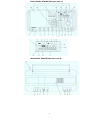
FRONT PANEL DESCRIPTION (See page 12)
LCD DISPLAY DESCRIPTION (See page 14)
REAR PANEL DESCRIPTION (See Paee 15)
3
SPECIFICATIONS
Frequency Range:
100 to 30.000 kHz (0.1 to 30 MHz).
87 to 108 MHz, 118 to 137 MHz.
AM. USB. LSB modes (0.1 to 30 MHz).
AM mode only for 118 to 137 MHz.
FM mode only for 87 to 108 MHz.
Line Audio Outputs:
Stereo left and right.
300 mV. 4.7K Ohms for each output.
Headphone Jack:
1/8 inch (3.175mm) stereo/mono type.
DC Power Requirements:
Input: 7-10 VDC 0 1 Amp. supplied from
AC ADAPTER, external DC Power
Sensitivity - SSB
(10 dB S+N/N):
Less than 0.5 uV, 0.1 to 30 MHz.
Sensitivity - AM
(10 dB S+N/N):
(1000 Hz. 30% Mod):
Less than 2.0 uV. 0.1 to 30 MHz.
Less than 4.0 pV, 118 to 137 MHz.
Sensitivity - FM
(20 dB S/N) (monaural):
Less than 4 uV, 87 to 108 MHz.
Frequency Stability
10 ppm, 0C to 50C
Frequency Accuracy:
Better than 100 Hz. c 25' C
Operating Temperature:
0C to +50C
Selectivity - SSB. AM:
6 kHz c -6 dB, less than 12 kHz 0 -60 dB.
4 kHz c -6 dB. less than 9 kHz c -60 dB.
2.3 kHz c -6 dB, less than 5 kHz c -60 dB.
Weight:
14.55 lbs. (6.6 kg). including
AC ADAPTER, (batteries NOT included).
IF Frequency - SSB. AM:
1st IF. 55.845 MHz.
2nd IF, 455 kHz.
Size - Width:
20 -7/8" (53.575 cm).
FM:
1st IF. 10.7 MHz (Single Conversion).
Image Rejection:
Greater than 60 dB. 0.1 to 30 MHz
Greater than 60 dB, 118 to 137 MHz.
Greater than 50 dB. 87 to 108 MHz
Supply or 5.7 to 9.0 VDC supplied by (6)
internally mounted "D" cell (1.5V)
batteries (not supplied).
Current requirements
(approximate) from
9.0 VDC Supply or
Batteries with 1/4 W
average Audio Output:
Mode Dependent:
510 mA minimum with lamp off,
830 mA maximum with lamp on.
IF Rejection.
AGC Performance
Greater than 80 dB. 55.845 MHz.
Greater than 80 dB. 455 kHz.
Threshold: 1 0 uV
Attack Time. 1 mSec.
Release Time: SLOW. 3 sec
FAST. 300 mSec
Less than 6 dB change in audio output for
90 dB RF input change (referenced from the
AGC threshold point plus 3 dB).
56 3/4" (1.414 meters) telescoping whip
(for use on all bands).
Ferrite rod antenna
(For use from 100 kHz through 1800 kHz)
External Antenna Inputs
0 1 to 30 MHz. 50 Ohm SO-239 connector
or 2 terminal compression connector for
500 Ohm input with ground
87 to 108 MHz and 118 to 137 MHz
75 Ohm "F" type connector
External Speaker Output
1 Watt each nominal into two 4 Ohm speakers
with 9 VDC supply voltage External jack is
1/4" (6.35 mm) and two-way for stereo output
2 Watts nominal when neither headphones
nor external speakers are plugged in
Power to Internal Speaker:
Depth:
8 1/2" (21.59 cm) including front handles.
Output:
Greater than +10 dBm @ 100 kHz spacing.
Greater than -20 dBm Q 5 kHz spacing.
Internal Antenna
9-1/4" (23.495 cm) with handle retracted.
Supplied AC ADAPTER
Input:
IP3 - Intercept Point
(@± 50 Ohm Ant. Input)
(Attenuator Off):
Height:
4'(10 16 cm), 4 Ohms.
Internal Speaker
4
120-230 VAC auto switchable. 50/60 Hz
with dual switchable plug wires.
9 VDC @ 1500 mA maximum.
Center conductor of connector is
positive.
CONTACT WITH THE AC ADAPTER.
10. Power Sources-This product should be operated only
from the type of power source indicated on the marking label of
the supplied AC Adapter. If you are not sure of the type of power
supplied to your home, consult your appliance dealer or local
power company.
11. Lightning-For added protection for this product during a lightning
storm, or when it is left unattended and unused for long periods of
time, unplug the AC adapter from the wall outlet.
12. Power Lines-An outside antenna system should not be
located in the vicinity of overhead power lines, other electric light or
power circuits, where it can fall into such power lines or circuits.
When installing an outside antenna system, extreme care
should be taken to keep from touching such power lines or
circuits as contact with them may be fatal.
13. Overloading-Do not overload wall outlets and extension
cords as this can result in a risk of fire or electric shock.
14. Servicing-Do not attempt to service this product yourself as
opening or removing covers may expose you to dangerous
voltage or other hazards. Refer all servicing to qualified service
personnel.
15. Damage Requiring Service-Unplug this product from the wall
outlet and refer servicing to qualified service personnel under
the following conditions:
a. When the AC adapter cord or plug is damaged.
b. If the AC adapter has been exposed to rain or water.
c. It the product does not operate normally by following the operating
instructions. Adjust only those controls that are covered by the operating
instructions. An improper adjustment may result in damage and will often require
extensive work by a qualified technician to restore the product to its normal
operation.
d. If the product has been dropped or the cabinet has been
damaged.
e. When the product exhibits a distinct change in performance-this
indicates a need for service.
16. Replacement Parts-When replacement parts are required, be
sure the service technician has used replacement parts
specified by the manufacturer or have the same characteristics
as the original parts. Unauthorized substitutes may result in fire,
electric shock or other hazards.
17. Safety Check-Upon completion of any service or repairs
to this product, ask the service technician to perform safety checks
to determine that the product is in proper operating condition.
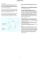
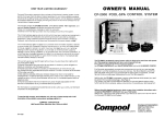
18. Outdoor Antenna Grounding-Before attempting to install
this product, be sure the antenna or cable system is grounded so as
to provide some protection against voltage surges and built-up
static charges.
2
2
a. Use No.10 AWG (5.3mm ) copper, No.8 AWG (8.4mm )
2
aluminum, No.17 AWG (1.Omm ) copper-clad steel or bronze
wire or larger, as ground wire.
b. Secure antenna lead-in and ground wires to house with
stand-off insulators spaced from 4 feet (1.22m) to 6 feet (1.83m)
apart.
c. Mount antenna discharge unit as close as possible to where
lead-in enters house.
d. A driven rod may be used as the grounding electrode where
othertypes of electrode systems do not exist. Refer to the National
Electrical Code, ANSI/NFPA 70-1990 for information.
2
e. Use jumper wire not smaller than No.6 AWG 13.3mm )
copper or equivalent, when a separate antenna grounding
electrode is used.
WARNING. TO PREVENT FIRE OR
ELECTRICAL SHOCK DO NOT EXPOSE
THIS PRODUCT'S AC ADAPTER TO RAIN OR MOISTURE
An appliance and cart combination should be moved with care. Quick stops, excessive
force and uneven surfaces may cause the appliance and cart combination to
overturn.
The lightning flash with arrow head symbol, within an equilateral triangle,is
intended to alert the user to the presence of uninsulated "dangerous voltage"
within the product's enclosure that may be of sufficient magnitude to constitute a risk
of electric shock to persons.
The exclamation point within an equilateral triangle is intended to alert
the user to the presence of important operating and maintenance
(servicing) instructions in the literature accompanying the appliance.
WARNING: TO REDUCE THE RISK OF FIRE OR ELECTRIC
SHOCK, DO NOT EXPOSE THIS PRODUCT'S AC ADAPTER TO
RAIN OR MOISTURE. DO NOT OPEN THE CABINET, REFER
SERVICING TO QUALIFIED PERSONNEL ONLY
CAUTION: TO PREVENT ELECTRIC SHOCK, DO NOT USE THE
AC ADAPTER WITH AN EXTENSION CORD RECEPTACLE OR OTHER
OUTLET UNLESS THE BLADES OF THE AC ADAPTER CAN BE FULLY
INSERTED TO PREVENT BLADE EXPOSURE.
ATTENTION: POUR PREVENIR LES CHOCS ELECTRIQUES,
NE PAS UTILISER CETTE FICHE POLARISEE AVEC UN
PROLONGATEUR, UNE PRISE DE COURANT OU UNE AUTRE
SORTIE DE COURANT, SAUF SI LES LAMES PEUVENT ETRE
INSEREES A FOND SANS EN LAISSER AUCUNE PARTIE A
DECOUVERT.
1. Read Instructions-All the safety and operating instructions
should be read before the appliance is operated.
2. Retain Instructions-The safety and operating
instructions should be retained for future reference.
3. Heed Warnings-All warnings on the appliance should
be adhered to.
4. Follow Instructions-All operating and use instructions
should be followed.
5. Cleaning-Unplug this appliance from the wall outlet before
cleaning. Do not use liquid cleaners or aerosol cleansers.
Use a damp cloth for cleaning.
6. Attachments-Do not use attachments that are not
recommended by the manufacturer or they may cause
hazards.
7. Water and Moisture-Do not use this product near
water-for example, near a bathtub, wash bowl, kitchen sink,
laundry tub, in a wet basement, or near a swimming pooland the like.
8. Accessories-Do not place this product on an unstable cart,
stand, tripod, bracket, or table. The product may fall, causing
serious injury to a child or adult, and serious damage to the
appliance.
9. Ventilation-This product should never be placed near
or over a radiator or heat register. This product should not be
placed in a built-in installation such as a bookcase or rack
unless proper ventilation is provided or the manufacturer's
instructions have been adhered to. Any slots or openings in
the,cabinet are provided for ventilation. To ensure reliable
operation of the product and to protect it from overheating,
these openings must not be blocked or covered. The
openings should never be blocked by placing the product on
a bed, sofa, rug, or other similar surface. KEEP CURTAINS
AND OTHER FLAMMABLE MATERIALS OUT OF DIRECT
EXAMPLE OF ANTENNA GROUNDING
5
TABLE OF CONTENTS
Thank you for purchasing the GRUNDIG SATELLIT
800 MILLENNIUM Shortwave Receiver. This receiver
has been designed and manufactured to high quality
standards, and will provide reliable operation for many
SPECIFICATIONS
4
IMPORTANT SAFEGUARDS
5
TABLE OF CONTENTS
6
GENERAL DESCRIPTION
7
POWER SUPPLY
8
AC ADAPTER
BATTERY OPERATION
AND INSTALLATION
8
INSTALLATION
UNPACKING
LOCATION
FIXED INSTALLATION
PORTABLE OPERATION
ANTENNA REQUIREMENTS
10
10
10
10
10
10
FRONT PANEL DESCRIPTION
12
LCD DISPLAY DESCRIPTION
14
REAR PANEL DESCRIPTION
15
GETTING STARTED
GENERAL OPERATING
INFORMATION
MICROPROCESSOR RESET
BEEP TONES
FIRST STEPS
DIRECT FREQUENCY ENTRY
SHORTWAVE 'METER' BAND
DESIGNATOR ENTRY
FREQUENCY RESOLUTION
FRONT PANEL LOCK (UNLOCK)
AM SYNCRONOUS OPERATION
SSB OPERATION
FM OPERATION
AGC OPERATION
16
years.
Please carefully read the Owner's Manual in order to
take advantage of the many interesting features that will
provide enjoyable listening to radio broadcasts around
tha world
MEMORY DESCRIPTION
STORING A MEMORY CHANNEL
RECALLING A MEMORY LOCATION
DELETING A MEMORY LOCATION
19
19
19
19
SCAN FUNCTIONS
20
SCAN DESCRIPTION
MEMORY CHANNEL SKIP
20
20
CLOCK AND TIMER FUNCTIONS
TIME DISPLAY
SETTING THE 24 HOUR CLOCKS
TIMER OPERATION
SETTING TIMER ON/OFF TIMES
ENABLING/DISABLING
TIMER OPERATION
21
21
21
21
22
SPECIAL USE FEATURES AND FUNCTIONS
LOCK ALL ENTRY TO KEYPAD
BROADCAST BAND TUNING STEP SIZE
DELETE ALL MEMORY CHANNELS
AUTOMATIC BANDWIDTH SETTING
WITH MODE SELECTION
DISABLE (ENABLE)
25
25
25
25
QUICK REFERENCE GUIDE
26
16
16
16
16
16
GLOSSARY OF TERMS
29
TROUBLESHOOTING
30
SUGGESTED REFERENCES
30
17
17
17
17
18
18
18
SERVICE INFORMATION
31
ONE YEAR LIMITED WARRANTY
31
MEMORY CHANNEL LOG
32
8
6
22
25
GENERAL DESCRIPTION
The SATELLIT 800 MILLENNIUM is a microprocessor
controlled, synthesized, world band receiver with continuous coverage capability from 100 kHz through 30 MHz
which includes the AM broadcast and shorwave bands.
Reception also includes FM broadcast (87 - 108 MHz) and
Aircraft (118 -137 MHz) bands. The SATELLIT 800
MILLENNIUM offers excellent sensitivity, selectivity,
dynamic range, and features that permit easy tuning of
desired stations. Conveniently located front panel controls
allow for rapid operator programming and ease of use. The
unit can be operated from either the supplied AC
ADAPTER or from six "D" cell batteries (not supplied) for
portable operation. A low battery voltage indication is
displayed when that condition exists.
(USB), and AM in the Shortwave, and AM broadcast bands. For
the Shortwave and AM broadcast bands, a selectable
sideband synchronous detector (SYNC) allows for enhanced
reception by eliminating or reducing distortion due to fading
signals. During FM broadcast use, stereo reception is
available through the use of headphones.
Three electronically switched IF filters are provided.
A programmable memory area allows for 70 independent
receiver set up memories. These memories do not require
battery backup and are thus unaffected by power
interruptions. All parameters associated with a particular
memory channel are stored including the frequency, mode,
bandwidth, fast or slow AGC, RF attenuator and
synchronous detector. These memory channels may be
accessed manually or through a time scan with each
channel monitored for a 5 second period.
Other built-in reception aids include selectable slow or fast
AGC, RF attenuator for use in strong signal handling
conditions, as well as treble and bass controls.
Two independent, real time clocks provide a local and
alternative time selection. Also provided is a two event
timer.
The front panel liquid crystal display provides feedback of
the current status of the receiver. The seven digit
frequency display provides resolution to 100 Hz accuracy in
the AM broadcast, Aircraft and Shortwave bands.
Resolution to 20 kHz is displayed in the FM broadcast band
mode. Backlighting of the display is selectable by a front
panel button. To prolong battery life with internal battery
operation, the backlighting automatically turns off after a
short delay following a function change or retuning of the
receiver.
Reception modes include Lower/Upper Sideband (LSB),
7
POWER SUPPLY
AC ADAPTER
The SATELLIT 800 MILLENNIUM receiver is supplied
with an auto-switchable AC ADAPTER to power it
indoors. The AC ADAPTER is designed to be plugged
into a wall outlet that supplies nominal 120 VAC, 60 Hz
or nominal 230 VAC 50 Hz power.
Keep curtains and other flammable materials out of
direct contact with the AC ADAPTER to avoid overheat
ing.
GRUNDIG assumes no responsibility for damage
due to operation with an AC adapter other than the
one supplied with this unit.
The AC adapter is supplied with a North American type
connector. To use the unit in countries using a European
type connector, plug the North American connector into
the US to Europlug adapter that is provided.
BATTERY OPERATION AND INSTALLATION
The SATELLIT 800 MILLENNIUM receiver is designed
to operate from either the supplied AC ADAPTER or
from six "D" cell batteries (not supplied). NOTE: Check
the batteries periodically for leakage. IF UNIT IS TO
BE STORED OR OTHERWISE NOT USED FOR AN
EXTENDED PERIOD OF TIME, REMOVE THE BAT
TERIES TO PREVENT CORROSION AND POSSIBLE
DAMAGE TO THE RECEIVER.
Connect the output connector of the AC adapter to the
9 VDC, 1 amp connector on the back of the receiver.
Inserted batteries are automatically disconnected as
soon as the AC adapter is plugged in to this connector.
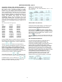
Battery Installation
(1) Position receiver with the back panel towards you.
(2) Remove battery access cover by pressing on the
corrugated area in the center of the cover and sliding it
to your left as far as it will go. Then gently pull it straight
out from the rear panel.
(3) Place 6 "D" cell alkaline type batteries into holder.
Make sure the batteries are in the proper polarity posi
tion as illustrated in Figure 1.
(4) Replace access cover by placing it over the left side
of the opening and then sliding it to the right.
NOTE:
The SATELLIT 800 MILLENNIUM does not rely on the
batteries for retention of memory channels. To ensure
that clocks and timers are maintained following the loss
of AC power or battery removal, the receiver must first
be connected to a source of AC power or have batteries
installed for a minimum of 10 minutes. If power is lost
after this minimum 'charge' time, clocks and timer
settings are maintained for a time period of approxi
mately 30 minutes.
8
POWER SUPPLY, cont'd.
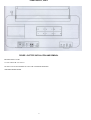
FIGURE 1: BATTERY INSTALLATION AND REMOVAL
BATTERY SUPPLY: 9 VDC
6 X IEC-LR20 OR "D" CELLS
DO NOT LEAVE BATTERIES IN UNIT FOR EXTENDED PERIODS.
CHECK BATTERIES OFTEN.
9
INSTALLATION
UNPACKING
Carefully remove the SATELLIT 800 MILLENNIUM and
included AC ADAPTER from the shipping carton and
examine them for evidence of damage. If any damage is
noted, immediately contact the transportation company
responsible for delivery or return the unit to the dealer from
whom it was purchased. Keep the shipping carton and all
packing material for the transportation company to inspect.
The original carton and packing material should be retained
for repackaging should it be necessary to return the receiver.
Inspect the packing material for any accessories or printed
material before storing the box. Locate the registration card,
fill it out. and immediately return it to Grundig to ensure
registration and validation of warranty.
ANTENNA REQUIREMENTS
(Refer to Figure 2, page 11)
The SATELLIT 800 MILLENNIUM incorporates rear panel
switches to select between the internal whip antenna and
various types of external antennas. The built-in 'WHIP'
antenna is available for use on all bands. For 100 kHz to 30
MHz operation, two antenna connectors are also provided.
'ANTENNA 1' is a 50 Ohm, SO-239 coaxial input requiring a
mating PL-259 connector. This input would typically be used
as the primary AM broadcast and shortwave band antenna
input. Antennas such as dipoles, trap dipoles, verticals and
beams will provide the best results, depending upon the
desired receiving frequency. 'ANTENNA 2' is a compression
terminal type connection, providing high-impedance (500
Ohms typical) input. Antennas such as long wires or endfed Zepps will provide the best results for 'ANTENNA 2'. For
reception in the 87-108 MHz and 118-137 MHz range, the
'FM/AIR' 75 Ohm "F" connector terminal is also provided.
Outside TV antennas, folded dipoles or coaxial antennas
will provide the best results with this input for reception of
the FM broadcast and Aircraft bands. The best antenna for
any of the previously mentioned inputs will depend on the
frequency range and time of day for the particular signal in
question. Refer to publications such as the ARRL
Handbook or ARRL Antenna Manual (available in most
public libraries) for help on selection and/or construction of
the antennas mentioned above.
LOCATION
For fixed locations, the SATELLIT 800 MILLENNIUM should
be operated from the AC ADAPTER. Keep curtains and
other flammable material away from direct contact with the
AC ADAPTER to avoid overheating which could result in
failure or fire.
FIXED INSTALLATION
After unpacking the unit, connect the antenna system to the
appropriate antenna input. Connect system ground to the
compression terminal marked 'GND'. Plug the output cable
of the AC ADAPTER into the 'External DC Input' connector
on the rear panel of the SATELLIT 800 MILLENNIUM
receiver. Plug the AC ADAPTER into a source of 120 VAC,
60 Hz or 230 VAC, 50 Hz power. Refer to the Figure 2 on
page 11 for the diagram of a typical fixed installation
If you have questions about antennas, contact Grundig
Technical Support at, 1(800) 872-2228 in the U. S. A., or 1
(800) 637-1648 in Canada.
PORTABLE OPERATION
For use in a portable environment, the SATELLIT 800
MILLENNIUM is operated from six (6) internally mounted "D"
cell batteries. These batteries are not supplied and must be
installed prior to portable operation of the receiver. See
BATTERY INSTALLATION section on page 9, Figure 1 of this
manual. For longest battery life, alkaline batteries are
recommended for this product. NOTE: REMOVE THE
BATTERIES IF THE RECEIVER IS TO BE STORED OR
OTHERWISE NOT OPERATED FOR AN EXTENDED
PERIOD OF TIME TO AVOID DAMAGE TO THE SATELLIT
800 MILLENNIUM DUE TO POSSIBLE BATTERY LEAKAGE
OR CORROSION EFFECTS. The SATELLIT 800
MILLENNIUM does not rely on the batteries for retention of
memory channels. To ensure that the clocks and timers
are maintainea following a loss of AC power or battery
removal, the receiver must first be connected to an AC
power source or have batteries installed for a minimum of 10
minutes. If power is lost after this minimum 'charge' time,
clocks and event timer settings are maintained for a period of
approximately 30 minutes.
10
11
FRONT PANEL DESCRIPTION
1. Power - Press this button to turn the unit on or off.
11. SSB USB-LSB- Press to select the SSB mode of
operation ('SYNC' must be turned off). Successive
depressions alternately select the 'LSB' or 'USB' modes as
displayed. The SSB mode of operation is not accessed in
either the FM or Aircraft band modes. Pressing the 'SSB
USB-LSB' button while 'AM SYNC' mode is engaged will
alternately select the upper or lower sideband portions of
the AM signal being received.
2. Headphone Jack - This connector accepts a 1/8"
stereo/mono headphone connector. Stereo reception is
possible only in the FM mode. All speaker outputs are
automatically switched off when using the headphones.
3. Volume - With the receiver on, adjust this control
clockwise to increase the audio level from the receiver's
speaker, external speaker, or from headphones. Be certain
to set the volume setting at the desired level for TIMER use.
12. Band - Repeatedly pressing this button will cycle
through the Air (Aircraft), FM (FM Broadcast), SW
(Shortwave) and AM (AM broadcast) bands.
4. Bass - This control adjusts the audio frequency
response at the low end of the audio spectrum. Adjust
clockwise for more bass response.
13. LCD Display - The backlit, liquid crystal display
provides the current status of the SATELLIT 800
MILLENNIUM such as frequency, mode, bandwidth, etc.
Refer to LCD DISPLAY DESCRIPTION on page 14 of this
manual for a full description.
5. Treble - This control adjusts the audio frequency
response at the high end of the audio spectrum. Adjust
clockwise for more treble response.
and
14. Tuning - The 'TUNING' knob and the
buttons are the primary tuning controls of the SATELLIT 800
MILLENNIUM. Clockwise rotation of the dial increases
frequency and counterclockwise rotation decreases
frequency. The dial also incorporates variable speed
tuning. The faster the dial is rotated, the faster the tuning
6. Air Band Squelch - This control is operational only for
the Aircraft band. The control allows muting of the
receiver's audio when no signals are present. Adjust the
control until background noise just disappears when no
signal is being received.
7. Attenuator - Press to turn on the built in 20 dB attenuator
to reduce the received signal strength in the AM broadcast
and Shortwave bands as required. The attenuator is not
active in the FM and Aircraft bands. Successive
depressions of the button toggle the attenuator on and off.
button increases and the
button
speed. The
decreases the frequency by fixed steps (10 kHz or 9 kHz
selectable in the AM broadcast band, 5 kHz on the
Shortwave band, 100 kHz on the FM broadcast band and
25 kHz on the Aircraft band) with each depression.
Pressing and holding either button will allow continuous
stepping up or down as long as the button is depressed.
8. AGC - Press to select either the Slow or Fast AGC
setting for the AM broadcast, Shortwave and Aircraft
bands. The AGC is not selectable in the FM mode.
9. Bandwidth - Press to select the desired bandwidth: 2.3
kHz, 4.0 kHz or 6.0 kHz. The bandwidth setting can be
programmed to be automatic with mode selection, or
manual. The default setting is for automatic selection. This
function has no action in the FM mode. The 6.0 kHz
bandwidth is automatically selected in the AM mode. The
2.3 kHz bandwidth is the default for the SSB modes. All
three bandwidths are selectable by successive depressions
of this button for the AM broadcast, Shortwave and Aircraft
bands. To disable the automatic bandwidth selection with
mode, start in the POWER 'OFF' mode and press and hold
the BANDWIDTH button while pressing the POWER button
to put the receiver in the POWER 'ON' mode. To enable
the automatic bandwidth selection with mode operation,
repeat the same procedure.
15. FUNCTION KEYS
STORE - This button is used to store the desired
frequency, mode, attenuator, synchronous detector, AGC
bandwidth, etc. as one of 70 memory channels. When
pressed, the 'MEMORY' symbol will flash in the display.
Enter a two digit number between '00' and '69' for the
desired memory channel. An audible beep will indicate
that the memory channel has been stored with the newly
entered settings.
10. AM Sync - Press to select the AM mode of operation.
Successive depressions toggle the synchronous detector
on and off. Press to turn the synchronous detector off
before selecting SSB modes. The 'AM' and 'AM SYNC'
modes are not accessible in the FM band. The 'AM SYNC'
mode is not accessible in the Aircraft band.
and
channels can be recalled by use of the
buttons. The 'Tuning' knob may be used totune from the
recalled frequency of the selected memory channel. Please
note that numerical entries are interpreted as frequency
entries if the 'MEMORY' channel number is not flashing.
MEMO - To recall a memory channel at any time, press
the 'MEMO' button and within three seconds of the button
depression, enter a two-digit number between '00' and '69'.
With 'MEMORY' displayed, other adjacent memory
12
FRONT PANEL DESCRIPTION, cont'd.
BEEP - The 'beep' tone is provided to indicate that
entries have been accepted or to notify of error. Press
this button to enable or disable the 'beep'.
16. Direct- Key-Input
Numeric Keys - Keys 0 thru 9 plus the'.' key are used to
make direct numeric entries of frequencies, memory
channel numbers and meter band designators.
VFO - Press to place the receiver in the normal variable
frequency tuning mode (VFO). Select desired frequency, mode, attenuator, synchronous detector, AGC,
Bandwidth, etc.
CLR LOCK - Press this key to clear an incorrectly entered
frequency or other value. Pressing and holding this button
for three seconds will cause the receiver to be locked in its
present configuration. All front panel push button controls
(except for the power button) as well as the tuning knob will
be ineffective, and "LOCKED" will appear on the LCD
display. To return to normal operating mode, once again
press the CLR LOCK key for three seconds.
SKIP - In the memory mode, press to skip the current
memory channel for a Scan operation. An 'S' will be
displayed to the right of the selected memory channel
number. When an 'S' is displayed next to a selected
memory channel number, press this button to restore the
memory channel for scan operation.
17. Signal Strength Meter - This meter indicates the
relative received signal level in S-units, and dB above S9.
Each S-unit between S1 and S9 equals an approximate 5
dB change in received signal strength. Each dB number
above S9 represents a 10 dB increase in received signal
strength.
SW BAND - Pressing the SW BAND button when SWW has
been selected with the BAND button (see 12) will cause
the '= portion of the SW - METER display on the LCD
to flash for approximately 2 seconds. During this 2
second interval, entering the meter designator for the
desired meter band will cause the receiver to go to the
low end of the frequency range for the desired meter
band. The frequency ranges for the defined meter
shortwave bands are as shown in the 'Shortwave Band
Designators' table which follows.
18. SET Keys
CLOCK - Pressing this button will display the current time of
the current clock. After three seconds, the display will revert
to the current frequency. Pressing and releasing this button
while the time is displayed will toggle the time display
between the two clocks (local or alternate). The timer will
operate according to the last displayed clock time. See
section on 'SETTING THE 24 HOUR CLOCKS' on page 21.
Shortwave Band Designators
Band
Low Freq
High Freq
120 Meter
2300 kHz
2500 kHz
90 Meter
3200 kHz
3400 kHz
75 Meter
3900 kHz
4000 kHz
60 Meter
4750 kHz
5060 kHz
49 Meter
5950 kHz
6200 kHz
41 Meter
7100 kHz
7600 kHz
31 Meter
9500 kHz
9900 kHz
25 Meter
11,600 kHz
12,100 kHz
22 Meter
13,570 kHz
13,870 kHz
19 Meter
15,100 kHz
15,800 kHz
16 Meter
17,480 kHz
17,900 kHz
13 Meter
21,450 kHz
21,850 kHz
11 Meter
25,600 kHz
26,100 kHz
TIMER - Pressing this button will activate the timer mode. If
the Timer has been activated, the 'TIMER' symbol will be
displayed even after the receiver is turned off. The receiver
will automatically turn on and off as programmed. See
section on 'SETTING TIMER ON/ OFF TIMES' on page 22.
LAMP - Press to turn the display backlighting on or off. With
internal battery operation, the backlighting automatically
turns off after a short delay following a function change or
retuning of the receiver in order to prolong battery life. Also,
the receiver senses Battery or AC operation, and allows the
lamp to remain lit if on AC.
19. Speaker - This is the opening for the internal
speaker for the SATELLIT 800 MILLENNIUM
RECEIVER.
DEL - Press and hold for three seconds to delete a
selected memory channel. An audible beep indicates
that the selected memory channel has been
deleted.
SCAN - Pressing this button starts scanning of the
current block of 10 channels. The receiver will stop at
each programmed memory channel for 5 seconds, then
increment to the next memory channel. Channels
programmed for SKIP will not be scanned. Press this
button again to stop the scan operation.
13
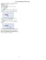
LCD DISPLAY DESCRIPTION
1. TIMER - This annunciator indicates the state of the Timer
as either Active or Inactive. Refer to the 'CLOCK AND
TIMER FUNCTIONS' section on page 21.
9. SW 120 METER - Indicates the shortwave band
designators that define a range of frequencies for each
band as follows:
2. LOCK - When illuminated, this annunciator indicates that
the Main 'TUNING' knob and all front panel keypads (except
for the POWER button) are not active.
Shortwave Band Designators
3. MEMORY 00 - This annunciator indicates current
memory location from 00 to 69. MEMORY will light when
the receiver enters the memory mode. Refer to
'MEMORY FUNCTIONS' on page 19.
4. BATT - When operating on internal batteries, 'BATT'
blinks to indicate a low charge on batteries. 'ATT' Indicates
that the built-in attenuator is activated.
5. AGC FAST/SLOW - indicates the AGC setting, Slow or
Fast.
6. AM SYNC - Indicates that the AM mode of reception is
on. If SYNC is also illuminated, then the synchronous AM
mode of detection is on.
7. USB - Indicates that the upper sideband mode of
detection is on.
LSB - Indicates that the Lower sideband mode of
detection is on.
Band
Low Freq
High Freq
120 Meter
2300 kHz
2500 kHz
90 Meter
3200 kHz
3400 kHz
75 Meter
3900 kHz
4000 kHz
60 Meter
4750 kHz
5060 kHz
49 Meter
5950 kHz
6200 kHz
41 Meter
7100 kHz
7600 kHz
31 Meter
9500 kHz
9900 kHz
25 Meter
11,600 kHz
12,100 kHz
22 Meter
13,570 kHz
13,870 kHz
19 Meter
15,100 kHz
15,800 kHz
16 Meter
17,480 kHz
17,900 kHz
13 Meter
21,450 kHz
21,850 kHz
11 Meter
25,600 kHz
26,100 kHz
10. AIR - indicates that the Aircraft band (118-137 MHz)
has been selected.
11. 7-Digit Readout - This display indicates the
operating frequency of the receiver. The frequency is
displayed in 'kHz' for the AM broadcast and Shortwave
bands. The FM and Aircraft band frequencies are
displayed in 'MHz'.
8. FM - Indicates that the FM mode of detection is on.
This mode is available only on the FM broadcast band (87
- 108 MHz).
12. SCAN 00 S - Indicates that the receiver is in the
memory channel SCAN mode and displays the number of
the currently scanned channel, from 00 to 69. In the
MEMORY mode, the 'S' illuminates to indicate that a
particular memory channel will be skipped over when the
SCAN operation is activated.
13. 6.0 4.0 2.3 - Indicates which IF filter is selected.
There is no indication in the FM mode.
14.
tuned in.
14
-
Indicates that a stereo FM broadcast station is
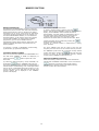
REAR PANEL DESCRIPTION
1. ANTENNA 1 - This connector is used when attaching
receiving antennas with coaxial feed lines of 50 Ohm
nominal impedance. It accepts a standard PL-259 plug. If
selected by the 'Shortwave Antenna Select' switch (item 2),
this input operates for the AM Broadcast and Shortwave
bands only (100 kHz to 30 MHz).
6. LINE AUDIO OUT -These RCA connectors provide
constant low level left and right audio sources that are
independent of the front panel VOLUME, TREBLE and
BASS control settings. They are designed to interface to a
tape recorder, CW/RTTY demodulators, stereo amplifiers,
etc.
2. SHORTWAVE ANTENNA SELECT - This switch selects
one of three possible antenna systems to be used for the
100 kHz to 30 MHz antenna input. Positions 1 and 2 select
ANTENNA 1 and ANTENNA 2 respectively, which are
described in items 1 and 5 on this section. When WHIP is
selected, the built in whip antenna, located at the rear righthand corner of the receiver's top, is connected. Also built
into the receiver is a ferrite rod antenna which also operates
when this switch is in the WHIP position, AND the receiver is
tuned between 100 kHz and 1800 kHz.
7. Battery Compartment - This compartment houses 6 IECLR20 or IEC R20 or 'D' cells to provide 9 VDC to the
receiver for portable operation. To gain access to the battery
compartment, press the corrugated area of the battery
compartment panel and slide it to the left. Then gently pull
the panel from the receiver. To replace the cover, simply
reverse this process.
8. EXT DC INPUT - Connect the AC ADAPTER output
cable to this connector. The receiver requires 9 VDC
power at approximately 1 Amp current. With external DC
power applied, the internal batteries are not used.
3. FM/AIR ANTENNA SELECT - This switch allows
selection of either the built-in WHIP antenna, or an
external 75 Ohm antenna connected at the FM/AIR
terminal (item 4) for the 87 - 108 MHz and 118 - 137 MHz
frequency ranges.
9. EXTERNAL SPEAKER - This connector accepts a
standard 1/4" diameter, 3 circuit, (stereo) phone plug for
connection of external 4 to 8 Ohm speakers.
4. FM/AIR Antenna - This "F" type input is designed for an
unbalanced 75 Ohm input connection that is encountered
with coaxial feeds. Connect to the FM connection of a
TV/FM outdoor antenna feed (splitter), if available. Folded
dipoles or coaxial antennas will also provide good results
with this input for reception of the FM broadcast and Aircraft
Bands. If selected by the 'FM/AIR Antenna Select' switch
(Item 3), this input operates for the FM Broadcast (87 - 108
MHz) and Aircraft (118 kHz to 137 MHz) bands only.
10. WHIP ANTENNA - The receiver has a built-in
telescoping antenna that can be used on all bands.
Note that the pivot point section of the antenna must be
exposed out of its nesting tube to permit moving the
antenna from its vertical orientation. Extend the
telescoping sections and position the antenna for best signal
reception. Be sure the corresponding rear panel antenna
select switch is set to the 'WHIP' position for WHIP antenna
reception.
5. ANTENNA 2 -This connector can be used to attach a
high impedance (500 Ohm nominal) antenna. Use the
'GND' (black) and '500 Ohm' (red) terminals for a 500
Ohm antenna. If selected by the 'Shortwave Antenna Select'
switch (Item 2), this input operates for the AM Broadcast and
Shortwave (100 kHz to 30 MHz) bands only.
15
GETTING STARTED
Enter frequency as follows:
(A) The Shortwave and AM broadcast bands enter in kHz
(Kilohertz). A maximum of 6 digits may he entered.
Examples:
GENERAL OPERATING INFORMATION
The SATELLIT 800 MILLENNIUM receiver has been
designed for ease of use. Please take a few moments to
read through this section and familiarize yourself with
general operating information.
700 KHz
MICROPROCESSOR RESET
A power-up reset routine will be activated anytime after the
receiver COMPLETELY loses power, either from internal
batteries or external DC input. This will be observed by the
front panel display illuminating all annunciators for 3
seconds, followed by the clock display. However, short
term power failures of up to 30 minutes are masked by an
internal back-up capacitor. This will allow ample time for
battery replacement without loss of the internal clock. Note:
Any programmed memory locations will NOT be lost under a
power-up reset due to the memory design of the
SATELLIT 800 MILLENNIUM.
Press
29,660 kHz
Press
14,258.1 kHz
Press
OR
Press
BEEP TONES
The SATELLIT 800 MILLENNIUM responds to all key
depressions with an audible beep unless the beep has been
disabled by the BEEP button. No beep is generated under
any condition for depressions of the TUNING keys when in
VFO mode. Beep tones indicate the following:
One short tone for a key depression.
One long, high tone when storing a memory channel.
One long, low tone for any illegal key depression.
* When the maximum number of allowed digits is entered,
the decimal point will be automatically placed between the 1
kHz and .1 kHz digits and need not be entered.
FIRST STEPS
Please refer to the front panel illustration and set the
controls as described below.
(1) Install 6 "D" batteries or connect AC ADAPTER.
(2) Fully extend the whip antenna and adjust to a vertical
position, or connect an external antenna to appropriate rear
panel terminals. Set rear panel 'ANTENNA SELECT'
switch(es) to appropriate position(s).
(3) Press 'POWER' and adjust 'VOLUME' to a comfortable
level.
(4) Select the desired band by pressing the 'BAND' button
until the desired band is displayed on the front panel display.
(5) Enter the desired frequency by using one of several
methods covered below.
(B) Aircraft and FM broadcast bands enter in MHz
(megahertz). A maximum of 5 digits may be entered for
FM, and a maximum of 7 digits may be entered for Aircraft
band entries.
Examples:
** The second depression of the '.' button acts as an
'ENTER' and causes immediate response to the entered
frequency. If you do not press the decimal '.'a second time
at the end, the receiver will automatically enter the frequency
after a slight delay.
97.7 MHz
Press
121.9 MHz
Press
Attempting to enter a frequency outside the tuning range of
the SATELLIT 800 MILLENNIUM receiver will cause the
ERROR annunciator to flash along with the error beep to be
heard. The receiver will then return to its previous settings.
DIRECT FREQUENCY ENTRY
Direct entry of a desired frequency is possible using the
'Direct-Key-Input' keys. While entering a frequency, if
an incorrect frequency is entered, pressing the '
'
button will clear the entry in progress and return the receiver
to its previous settings. The second depression
of the decimal
button acts as an 'ENTER' and causes
immediate response to the entered frequency. If you do
not press the decimal
.
button a second time
at the end, the receiver will automatically enter the
frequency after a slight delay.
16
GETTING STARTED, cont'd.
SHORTWAVE 'METER' BAND DESIGNATOR ENTRY To
facilitate tuning to particular sections of the shortwave band
that contain many worldwide broadcasts of news,
information and music, the SATELLIT 800 MILLENNIUM
permits entry of the 'METER' band designator. In some
cases, the worldwide broadcast station may not announce its
exact operating frequency, but will announce the 'METER'
band in which it is operating or to which band it will move to
improve worldwide reception at a particular time of day. By
entering this 'METER' band number, the receiver
automatically tunes to the low frequency end of the
corresponding 'METER' band. The search for the new
station location is thus limited to a particular smaller section
of the entire shortwave band spectrum. The Shortwave Band
Designators and corresponding frequency ranges are as
follows:
FREQUENCY RESOLUTION
The SATELLIT 800 MILLENNIUM tunes in the
following steps:
Shortwave Band Designators
FRONT PANEL LOCK (UNLOCK)
Band
120 Meter
90 Meter
75 Meter
60 Meter
49 Meter
41 Meter
31 Meter
25 Meter
22 Meter
19 Meter
16 Meter
13 Meter
11 Meter
Low Freq
2300 kHz
3200 kHz
3900 kHz
4750 kHz
5950 kHz
7100 kHz
9500 kHz
11,600 kHz
13,570 kHz
15,100 kHz
17,480 kHz
21,450 kHz
25,600 kHz
High Freq
2500 kHz
3400 kHz
4000 kHz
5060 kHz
6200 kHz
7600 kHz
9900 kHz
12,100 kHz
13,870 kHz
15,800 kHz
17,900 kHz
21,850 kHz
26,100 kHz
All keyboard entries, display settings, and entries from the
tuning knob can be locked if desired. First, be sure the
SATELLIT 800 MILLENNIUM is not in SCAN mode.
button which is one of the 'DirectPress and hold the
Key-Input' keys. The LOCK annunciator will light indicating
the front panel controls are LOCKED out. POWER on/off will
still function as well as VOLUME, BASS, TREBLE, and AIR
BAND SQUELCH. Press and
button to unlock. The LOCK annunciator will
hold the
extinguish, indicating the front panel controls are once again
active.
AM SYNCRONOUS OPERATION
Press the 'BAND' button as required to enter the shortwave
band tuning mode. At this point, you can enter a frequency
with the 'Direct-Key-Input' buttons, or use the TUNING knob
and/or the
and
For general tuning and listening, normal AM is best. If,
however, the received signal sounds distorted, or
interference from adjacent stations is present, AM
synchronous should be engaged. The synchronous detector
in your receiver can greatly reduce the severe audio
distortion that can occur due to signal fading. The detector
also permits selectable tuning to either the upper or lower
sideband portion of an AM signal. Since most all AM (LW,
MW and SW) broadcasting generally uses double-sideband
transmission, detection of either of the two sidebands results
in full reception of the transmitted information. The
selectable sideband tuning and detection not only aids
reception by permitting tuning to the stronger or less
distorted sideband, but also permits rejection of the
sideband nearer to the interfering signal(s). For Example:
buttons to change frequency.
To enter a shortwave band 'METER' designator, press the 'SW
BAND' button to display a flashing 'METER' number entry
prompt. The prompt will flash for approximately 3 seconds
after the SW BAND button is pressed. While it is still flashing,
enter one of the listed two or three digit Band numbers
corresponding to the desired 'METER' band designator using
the 'Direct-Key-Input' buttons. While the 'METER'
and
buttons can also
annunciator is flashing, the
be used to step quickly from band to band. After selection of
the 'METER' band, use the TUNING knob or
and
buttons to change the frequency, or press the 'Direct-KeyInput' keys to make a direct frequency entry.
17
GETTING STARTED,
cont'd.
The synchronous detector will lock to the strongest signal
that is within the IF passband when it is activated. Most of
the time, the strongest signal will be the carrier of the desired
signal. First, be sure the main tuning is set to within 1 kHz of
the desired station's transmitting frequency. Press the 'AM
SYNC' button to activate synchronous operation. If adjacent
channel interference or any other undesired signal is
sufficiently strong, the synchronous detector may lock to it
instead. In that case, press the 'AM SYNC' button again to
turn the synchronous detector off, and repeat the tuning
process. For severe cases of fading, set the audio bandwidth
to 4 kHz. If interference is present, press the SSB USBLSB
button to select the sideband with the least interference once
'AM SYNC' has been selected. If the interference is
sufficiently severe to prevent reception, select a narrower IF
bandwidth and retune to the desired signal. After reception
is obtained, select a wider bandwidth and/or alternate
sideband if desired. When 'AM SYNC' has been activated,
moving the TUNING knob will cause the SYNC circuit to
momentarily disengage (indicated by 'SYNC' flashing), then
back on again when tuning has stopped. AM SYNC does
not function on the AIR band, and will not operate properly
on intermittent transmissions such as those encountered on
CB radio, and AIR bands. For those types of transmissions,
use the AM mode. Press the AM SYNC button to turn
the synchronous detector off before selecting LSB or
USB modes.
FM OPERATION
FM reception is perhaps the easiest mode to use on the
SATELLIT 800 MILLENNIUM. The AGC and BANDWIDTH
settings are not used in FM. In fact, attempting to activate
these buttons will result in an 'ERROR' beep. All FM stations
in the U.S. end in an odd 100 kHz, i.e. 97.7 MHz, and are
spaced 200 kHz apart. The SATELLIT 800 MILLENNIUM
has the ability to tune in 20 kHz steps to allow tuning in
between stations to help eliminate interference to weaker
stations that could be covered up by stronger adjacent
stations. Additionally, when headphones or external
speakers are used, true stereo reception is possible. The
front panel stereo
will light when a stereo station is tuned in.
indicator
The receiver will automatically switch to stereo and provide
left and right audio from the headphone jack, line output
jacks, or external speaker jack. If the headphones or
external speakers are removed while listening to a stereo
broadcast, the receiver will provide monaural audio from the
internal speaker, and the front panel stereo indicator will
disappear.
AGC OPERATION
The SATELLIT 800 MILLENNIUM provides the ability to
select a Slow or Fast AGC setting. Either of the two settings
will permit automatic control of the receiver's gain thereby
producing a constant audio output free of distortion.
Generally, the Slow AGC setting is preferred for reception of
AM and SSB signals. The Fast AGC setting allows more
rapid automatic receiver gain adjustment to quickly fading
signal levels. The AGC does not function in the FM mode.
SSB OPERATION
Tuning in a single sideband (SSB) signal can be somewhat
frustrating for the first time listener. In either of the SATELLIT
800 MILLENNIUM's SSB modes, LSB (lower sideband), or
USB (upper sideband), the receiver will select the 2.3 kHz
bandwidth automatically (the receiver may be programmed to
NOT automatically select a bandwidth. Refer to 'Automatic
Bandwidth Setting With Mode Selection DISABLE
(ENABLE)' in,the 'Special Use Features and Functions'
section of this manual). Generally, LSB is used below 10
MHz and USB is used above 10 MHz. When initially tuning
in the desired station, tune slowly. If the station is
unintelligible, try the other sideband, again tuning slowly. A
station tuned in on the wrong sideband is totally
unreadable but a station mistuned on the correct sideband
may sound like 'Donald Duck'. Further tuning will result in a
more normal voice pitch.
18
MEMORY FUNCTIONS
MEMORY DESCRIPTION
The SATELLIT 800 MILLENNIUM contains 70 memory
locations that can be used to store and recall commonly
monitored frequencies. These 70 locations are divided
into blocks of 10, ie. 00-09, 10-19 20-29, etc. This allows
convenient grouping of frequencies. As an example, 0009 could be AM broadcast stations, 10-19 could be FM
broadcast stations, 20-29 could be various time stations
such as CHU and WWV, etc. With memory locations
programmed, you can use the SCAN function to
automatically monitor desired memory frequencies. The
following operating parameters may be stored in any
memory location:
RECALLING A MEMORY LOCATION
(I) Frequency, (2) Mode, (3) Bandwidth, (4) AGC setting,
(5) Attenuator, (6) Synchronous detector.
The large 'TUNING' knob may be used to tune from the
frequency that was stored in the selected memory channel.
The 'MEMORY' symbol turns off, but the last memory channel
STORING A MEMORY CHANNEL
First, be sure that the SATELLIT 800 MILLENNIUM is in
the VFO mode (MEMORY or SCAN not displayed). If
button will cause the
number still shows. Pressing the
receiver to return to the last selected memory channel
number and the 'MEMORY' symbol will turn on.
button to place unit in the
required, press the
VFO mode.
(A) Select the desired frequency, mode, bandwidth, etc.
DELETING A MEMORY LOCATION
Select the memory channel to be deleted as described in
'RECALLING A MEMORY LOCATION'. Press and hold the
(B) Press the
button. 'MEMORY' will light and
the memory channel number will flash for approximately 3
seconds. While it is still flashing, enter a two-digit number
from 00 to 69. A confirmation beep will be heard. (C) The
receiver will return to the VFO mode and the last used
memory location will be displayed in the 'MEMORY'
portion of the display.
button for 3 seconds. A beep will be heard to
indicate that the contents stored in the selected memory
channel number have been deleted.
To select a specific memory channel, press the
button. This will cause 'MEMORY' to light on the front panel
display, and the MEMORY channel number will flash for
approximately 3 seconds. While it is still flashing, enter a
two digit number of the desired memory channel to be
received. Make certain that the successive button
depressions are made within 3 seconds of each other. Other
memory channels may be selected by pressing the
button and entering two digit
numbers. If a channel number is selected that is empty,
'Error' will flash.
19
SCAN FUNCTIONS
SCAN DESCRIPTION
The SATELLIT 800 MILLENNIUM provides a time scan
function of programmed memory channels using the
Press the
button again to stop the scanning action.
Note that if channels 29 and 40 were stored, they would not
be included in a scan of the channels starting with a '3' as
the most significant digit of the channel number.
MEMORY CHANNEL SKIP
A memory channel can be skipped for scan operations.
While in the MEMORY mode, press the'( SKIP I' button.
The display will indicate that the 'SKIP' function has been
stored for that particular memory channel number. An 'S'
will be displayed to the right of the memory channel number
on the display. Repeat the same sequence as described to
remove the 'SKIP' function from a memory channel number.
button. Scan will begin and end within a 10
channel block of programmed memory channels as
indicated by the most significant digit of the selected
memory channel number.
Example for MEMORY CHANNEL 'SKIP':
Refer to the previous example on this page. Suppose it is
desired to skip the memory channel number '34' from the
scan action:
From the normal variable frequency tuning and reception
mode (VFO) or from the Memory mode, press the
button followed by the two-digit number '34'.
The receiver will stop at each programmed memory channel
within the block for 5 seconds and then increment to the next
memory channel. Memory channels that are programmed to
be skipped will not
be scanned. The 'SCAN' symbol will be displayed for the
duration of the scan action. Scanning will continue until the
'SCAN' button is pressed again.
button. An 'S' will illuminate to the right of
Press the
the displayed '34'. When the scan action is initiated, all
channel numbers 30 through 39, except 34, will be
scanned. Note that the memory contents of channel 34 still
remain. It is skipped over only in the scan sequence.
Example for SCAN:
To allow channel 34 to again be included in the scan
Suppose that memory channels 30 through 39 are
programmed and it is desired to scan these channels. To
sequence, press the
digit number '34'.
button
initiate the scan action, press the
followed by the two-digit channel number entry (can enter 30
through 39 for this example).
button followed by the two-
Press the
button to remove the 'SKIP' function from
channel 34 for this example. The 'S' indicator in the display
will turn off.
Press the
button. The receiver will begin scanning
from the selected memory channel and continue scanning in
sequence: '30'- '31' -'32' - etc.
20
CLOCK AND TIMER FUNCTIONS
TIME DISPLAY
The SATELLIT 800 MILLENNIUM incorporates a dual time
clock allowing two 24 hour clocks to be set and
maintained. During loss of AC power, or during battery
changing, clock operation is maintained for a period of
approximately 30 minutes, if the receiver has been
connected to an AC power source or had the batteries
installed for a minimum time of 10 minutes. The two-event
timer functions are also derived from the last displayed clock,
therefore the clocks must be set first for proper TIMER
operation.
TIMER Settings are also maintained through a power loss
for a period of approximately 30 minutes.
Example for Local Clock Set:
With frequency displayed, suppose it is desired to set '13:01';
Press and hold the
button until the colon flashes
rapidly.
Press the following sequence of numeric buttons:
When the actual time is 13:01, Press the
The clock is now started.
TIMER OPERATION
The SATELLIT 800 MILLENNIUM includes two programmable event timers allowing the receiver to turn ON or OFF
at preset times. The timers may be used separately or
together and may recall a currently displayed frequency,
memory channel or a combination of both. In addition,
programming only an OFF time provides a Sleep timer, and
programming only an ON time provides a Wake timer. Note
that the timers, when activated, respond to the last
displayed clock. Programming the timers is a two step
process. Step one is to set the ON and OFF times. Step two
is to assign a frequency or memory channel to a timer.
This assignment occurs when the desired timer is actually
enabled.
button once will display the current
Pressing the
time of the current clock. After approximately 3 seconds,
the display will revert to the current frequency. Pressing
and releasing the button while time is being displayed will
toggle the time display between the two clocks. Normally
the clock accompanied by the 'L' on the display will be set
with the local time, while the alternate clock will be set to
display GMT (UTC) time. The SATELLIT 800 MILLENNIUM
will display the selected clock when the POWER switch is
turned off.
SETTING THE 24 HOUR CLOCKS
Select local ('L) or alternate time clock by pressing the
button.
Press and hold the
button for three seconds until
the colon begins flashing rapidly. If the 'L' is illuminated, you
are setting the local clock. With no 'L' displayed, you are
setting the alternate clock. Either clock can be set first.
Time is entered in a 24 hour format. Enter the time in
'HH:MM', with the 'colon' understood.
The
button.
button can be pressed to erase erroneous
button to start the clock when
entries. Press the I
the actual time value agrees with the entered time. The colon
will flash at one second intervals when the clock is running.
21
CLOCK AND TIMER FUNCTIONS,
SETTING TIMER ON/OFF TIMES
Press
Press and hold the
button for approximately
2 seconds until the 'TIMER' annunciator turns on, and 'ON'
flashes. The 'ON' Time will also be indicated in the
frequency portion of the display (same readout format as the
clock) as well as the number '1' or '2' displayed to the right of
the time. The number '1' or '2' indicates which one of the two
event timers you are programming.
Press the button sequence
Press the desired 'Direct-Key-Input' buttons to enter a new
'ON' time. Enter the time in 'HH:MM' and in 24 hour format.
Press
button to remove the 'ON' time, to use the
Press the
timer as a Sleep timer. For a Wake timer, program an 'ON'
time and remove the 'OFF' time.
To set the 'OFF' time, press the
display 'OFF' time.
If it is desired to set 'Timer 2', use the same procedure as
that for 'Timer 1'. Otherwise,
button again to
,
to exit the 'Setting Timer' operation
Press
and return to normal frequency display.
Press the desired 'Direct-Key-Input' buttons to enter a new
'OFF' time. Enter the time in 'HH:MM' and in 24 hour format.
Press the '' button to remove the 'OFF' time, if desired.
ENABLING/DISABLING TIMER OPERATION
1)Example for Setting Timer '1'
With frequency displayed, suppose it is desired to set
Timer '1' for a local ON Time of '16:59' and an OFF Time
of ' 18:01'.
button.
Press the
The 'TIMER' symbol will light in addition to either or both
the timer '1' or timer '2' indication. After 2 seconds with no
entry, the display reverts back to frequency readout. Timer
'1' can be disabled/enabled by pressing the '1' numeric
digit on the 'Direct-Key-Input' keypad while the timer
enable display is showing. Timer '2' can be
disabled/enabled by pressing the numeric digit '2' on the
'Direct-Key-Input' keypad while the timer enable display is
showing.
Prior to enabling either or both timers, consider one of two
possible cases for each timer:
eg.) -To Enable TIMER '1' –
Action:
(1) '-' is displayed: Press the
Press the
time.
button again to enter TIMER 2 'ON'
Press the
time.
button again to enter TIMER 2 'OFF'
button to save the settings and
Finally, press the
switch the display to normal readout values.
Press and hold the
button for 2 seconds.
(2) '1' is displayed: Press the
display '1'.
button to display '1'.
button twice to again
It is important to note that the timer is enabled only when
the timer is deliberately changed from a '-' to a '11', or to a
'2'.
Even if the '1' or '2' is already displayed, the timer is not
enabled unless the '-' to '1' or '2' transition occurs.
Setting a '-' for either timer DISABLES the respective timer.
Press the button sequence
22
CLOCK AND TIMER FUNCTIONS, cont'd.
Timers '1' and '2' Enabled
Press
Press 'CLR/LOCK' (enters no OFF Time for timer '1')
Timer '1' Enabled: Timer '2' Disabled
If either one or both the timer '1' or timer '2' are enabled, the
Press
TIMER symbol will continue to be displayed after the receiver
is turned off. Be certain to leave the volume setting at the
desired level. The receiver will automatically turn on and off
as programmed. If both timers are disabled ('-' '-' is
displayed), the timer programming in either or both timers is
retained, but no TIMER action will take place until one or
both are enabled.
Press the button sequence
.
FM
2)Example for Setting Overlapping Events:
With frequency displayed, suppose it is desired to record a
one hour program on one frequency with a beginning time of
'16:59' and an ending time of '18:00', and a second program
on the same frequency with a beginning time of '18:00' and
an ending time of '19:01'.
Press
Action:
Press and hold the
button for 2 seconds.
Press the button sequence
Press the button sequence
Press
23
for normal frequency display.
.
CLOCK AND TIMER FUNCTIONS, cont'd.
3) Example for Setting Events on Two Different Memory
Channels:
PROGRAMMING MEMORY 08 in Timer '1' and
MEMORY 29 in Timer '2':
With frequency displayed,
Press 'MEMO' followed within two seconds by button
sequence:
Press
the
followed within 2 seconds by depression of
button until the '1' is displayed with 'MEMORY 08'.
After 3 seconds, the display reverts to the frequency readout.
With frequency displayed, press
followed within 2
seconds by button sequence
.
Press
of the
followed within 2 seconds by depression(s)
button until the '2' is displayed with 'MEMORY 29'
indicated.
After 3 seconds, the display reverts to the frequency readout.
To set an event with no memory channel to be recalled, exit the
memory mode before enabling the event. In this case, the
SATELLIT 800 MILLENNIUM receiver maintains its current
settings. Refer to 'ENABLING/ DISABLING TIMER OPERATION'
to enable or disable either of the two timers.
24
SPECIAL USE FEATURES AND FUNCTIONS
The SATELLIT 800 MILLENNIUM receiver has several
special features that are referred to in the main body of
this Owner's manual but may require additional explanation.
If the step size was 10 kHz prior to performing the above
procedure, then the 9 kHz step size for the broadcast band is
now programmed. To change back to 10 kHz, repeat the
same procedure.
LOCK ALL ENTRY TO KEYPAD
The receiver front panel buttons with the exception of the
DELETE ALL MEMORY CHANNELS
If it is desired to delete all programmed memory channels,
perform the following procedure:
button and 'TUNING' knob may be locked or
disabled by pressing and holding the
seconds.
Press the
while pressing the
button and hold for 3 seconds. A
confirmation beep will be heard when the
pressed.
With POWER OFF, Press and bold the
button for 3
button to put the SATELLIT 800
MILLENNIUM receiver in the POWER 'ON' mode.
is
button until a confirmation beep is heard
Hold the
to indicate that ALL memory locations have been cleared.
will appear on the front panel display
after 3 seconds to indicate that the front panel buttons and
TUNING control are locked.
AUTOMATIC BANDWIDTH SETTING WITH MODE
SELECTION DISABLE (ENABLE)
The SATELLIT 800 MILLENNIUM receiver permits automatic
setting of the bandwidth appropriate for each mode of
detection. For example, 6.0 kHz bandwidth would be
selected automatically for AM mode operation, and 2.3 kHz
bandwidth would be selected for SSB mode. Of course,
pressing the 'BANDWIDTH' button temporarily overrides the
automatic setting until a mode change is made. The setting,
automatic or manual bandwidth selection with mode, is held
in nonvolatile memory and is not lost during power loss or
during battery changing. To disable the automatic bandwidth
with mode;
Press
again for 3 seconds to unlock the front
panel buttons and tuning control. The beep will again
be heard when the button is pressed and the
indicator on the front panel display will disappear
after 3 seconds, indicating that the TUNING control
and front panel buttons have been released.
BROADCAST BAND TUNING STEP SIZE
In the AM broadcast band, the SATELLIT
MILLENNIUM receiver increments the frequency in
800
With POWER OFF, Press and hold the 'BANDWIDTH'
10 kHz steps when pressing the
and
buttons.
The 10 kHz step size is practical for tuning the U.S. and
Canadian broadcast bands. However, the step size can
be changed to 9 kHz to permit practical tuning of European broadcast stations. The tuning step size is held in
nonvolatile memory and thus is not lost during power
failure or battery changing. To select the alternate step
size:
With POWER OFF Press and hold the
button
button while pressing the
button to put the receiver in
the POWER 'ON' mode.
To enable 'Automatic Bandwidth Selection with Mode'
operation, repeat the same procedure.
button
button to put the SATELLIT 800
while pressing the
MILLENNIUM receiver in the POWER 'ON' mode.
25
QUICK REFERENCE GUIDE
The
symbol indicates that the button is to be
pressed within three seconds.
Select normal frequency display (VFO) (page 13)
Press 'VFO'
Press 'BAND'
Select Band (page 12)
Press 'BAND' button (scrolls through Aircraft, FM Broad cast,
Shortwave, and AM Broadcast bands). When in Shortwave
mode, press
two or three digit entry from 'DirectKeyInput’ keypad for Shortwave Meter band designation.
Adjust Frequency (page 12)
Select Band. Turn TUNING knob, Press
'Direct-Key-Entry' keypad.
Select Mode (page 12)
Select SYNC (page 12)
and
keys, use
Press 'AM SYNC' for displayed 'AM'
Press 'AM SYNC' to toggle to 'AM SYNC'
Press 'SSB USB-LSB' to toggle between 'USB' and 'LSB' when
'AM SYNC' is displayed.
Press 'BAND' as required to display 'FM'.
Press 'SSB USB-LSB' to select SSB mode when 'AM' is
displayed for SSB mode (AM Sync must be off).
With unit in 'AM' mode, press 'AM SYNC' for displayed
'AM SYNC'
Select Bandwidth (page 12)
Press 'BANDWIDTH' for displayed '6.0', '4.0' or '2.3'
(not active in FM mode).
Select AGC (page 12)
Press 'AGC' for displayed 'S' or 'F' (not active in FM mode).
Attenuator On or Off (page 12)
Press 'ATT' for displayed 'ATT' or blank
(not active in 'FM' or 'AIR' modes).
Set Time (Page 21)
Press
to display either Local ('L') or alternate time.
Press
and hold until colon flashes. Use keypad to
enter time in 'HH:MM' format.
Display Time (Page 21)
Set Timer On/Off Timer (page 22-23)
Press
to start clock.
Press
(
to display alternate time).
Press
(hold) until 'TIMER ON' shows. Use 'Direct-Key
Input' keypad to enter On time for TIMER '1'.
Press
again.
Use 'Direct-Key-Entry' keypad to enter Off time for TIMER '1'.
Press
again.
Use 'Direct-Key-Entry' keypad to enter On time for TIMER '2'.
Press
again.
Use 'Direct-Key-Entry' keypad to enter Off time for TIMER '2'.
Press
26
again to leave the set mode.
QUICK REFERENCE GUIDE, cont'd.
Activate (Enabling) Timer (page 22)
Lock (or Unlock) Controls (page 14)
Press
'1' and/or'2'
Press and hold
until
is displayed
(extinguishes). Pushbuttons and TUNING knob are inactive
(active).
Lamp On/Off (page 13)
Disable Beep (page 13)
Press
to turn display backlight on or off.
Press
to enable or disable audio beep.
MEMORY FUNCTIONS
Store Memory Channel (page 19)
Select bandwidth and adjust frequency.
Press
. 'MEMORY' will light and channel number
flashes,
use 'Direct-Key-Input' keypad to enter two digit
memory channel number from '00' to '69'.
Recall Memory Channel (page 19)
Press
, desired two number digit from
'Direct-Key-Input' keypad or use
Skip Memory Channel (page 20)
and
buttons.
Press
, desired two digit number from
'Direct-Key-Input' keypad.
Press
.
'S' will appear next to memory channel number.
Delete a Memory Channel (page 19)
desired two digit number from 'Direct-Key-Input'
keypad.
Press and hold
Delete all Memory Channels (page 25)
With power off, press
for 3 seconds.
while pressing the
button.
Hold
until confirmation beep indicates all channel
memory has been deleted.
SCAN MODE
The scan feature only works with channels
programmed within a block (page 20)
Scan memory (page 20)
desired two digit number from 'Direct-Key-Input'
keypad to select the block to scan.
REAR PANEL CONTROLS
Shortwave Antenna Select (page 15)
Then
to start scan.
Select '1', '2', or 'WHIP' as desired. Connect appropriate
antenna(s).
FM/AIR Antenna Select (page 15)
Select either 'EXTernal' or 'WHIP' as desired. Connect
appropriate antenna.
27
GLOSSARY OF TERMS
1) AC Input - Alternating Current power source available
at wall outlet sockets.
12) HF - High Frequency band extends from
approximately 1.5 MHz to 30 MHz.
2) AM - Signals in which the information is conveyed by
amplitude changes of the signal. Amplitude Modulation
is used for the AM broadcast bands.
13) LCD - Liquid-Crystal Display - Low power consump
tion displays used for wristwatches and information
displays on many types of electronic equipment.
3) AGC - Automatic Gain Control which is employed in
receivers to adjust the amount of gain in the receiver's
circuitry to prevent distortion and maintain a nearly
constant audio volume level over wide variations in
received signal strength.
14) LSB - Lower Side Band - The lower frequency
portion, excluding the carrier, of an AM signal. A
single-sideband signal, in this case the lower sideband,
contains all of the modulation information of amplitude
modulation in one half the bandwidth.
4) Attenuation - Loss, as applied in the text of this
manual, added prior to the input stages of the receiver to
reduce the level of very strong signals that may occur on
certain bands, in certain locations, at certain times or a
combination of all three factors. Each 10 dB (decibel)
step reduces the power of the received signal by a factor
of ten.
15) RF - Radio frequency.
16) RTTY - Radio Teletype communications.
17) Squelch - A user controlled adjustment which mutes
the audio output below a certain signal strength.
18) Synchronous Detector - An amplitude modulation
detector which utilizes a replica of the original transmit
ted carrier signal to improve the reception of weak
signals.
5) CW - Continuous Wave transmission signals. Actually,
the signal is keyed on and off at precise intervals to
convey information. Morse code is the most common
CW signal.
19) Synthesized - Capable of generating a large
number of different output frequencies, all related to a
single, highly stable reference source.
6) DC Input - Direct Current power source such as is
available from batteries or regulated power supplies.
7) Dynamic Range - Ability of the receiver to faithfully
reproduce high quality audio over a wide range of signal
strength conditions - from very weak signals to very
strong signals.
20) Up Conversion - A frequency conversion technique
that translates an incoming RF signal to a higher fre
quency.
21) USB - Upper Side Band - The higher frequency
portion, excluding the carrier of an AM signal. A single
sideband signal, in this case the upper sideband,
contains all of the modulation information of amplitude
modulation in one half the bandwidth.
8) Frequency - Rate of reoccurrence in hertz or cycles
per second of an electromagnetic wave or carrier.
9) FM - Signals in which the information is conveyed by
frequency changes of the signal. Frequency Modulation
is used for the FM broadcast bands.
22) UTC - Universal Time Coordinated.
23) VFO - Variable Frequency Oscillator.
10) Electronically Switched Filter - A multi-bandwidth
filter with high adjacent channel attenuation switched
electronically.
24) VHF - Very High Frequency band extends from
approximately 30 MHz to 300 MHz.
11) GMT - Greenwich Mean Time.
29
TROUBLESHOOTING
PROBLEM
PROBABLE CAUSE
SOLUTION
No front panel display or light.
(A) Power connection.
(B) Defective AC ADAPTER unit.
(C) Batteries are discharged or not
installed for portable operation, no
AC power.
(A) Check power supply cables.
(B) Check AC ADAPTER.
(C) Check/install batteries for
portable operation.
No signals heard when antenna is
connected or sensitivity is low.
(A) Incorrect antenna input
selected.
(B) 'ATTENUATOR' enabled.
(A) Select correct antenna input.
S meter indication but no sound
heard.
(A) Improper mode selected.
(B) External speaker connected but
defective.
(A) Check mode selection.
(B) Check external speaker.
No front panel operation such as
tuning, frequency entry, etc.
(A) Lock enabled.
(A) Press
Timer does not operate.
(A) Clock(s) not set.
(B) Timer not properly set.
(B) Turn off 'ATTENUATOR'.
and hold for 3
seconds to unlock front panel.
(C) Alternate clock selected.
(A) Set clock(s).
(B) Set clock(s) and program timer
ON/OFF times.
(C) Check that last displayed clock
is the desired one for timer event.
SUGGESTED REFERENCES
(1) Passport to World Band Radio
Published by:
International Broadcasting Services, Ltd.
P. 0. Box 300
Penn's Park, Pennsylvania 18943
(2) World Radio TV Handbook
Billboard Publications Inc.
1515 Broadway New York, NY 10036
(3) The ARRL Antenna Book
Published by:
The American Radio Relay League
225 Main Street
Newington, CT USA 06111
Copyright c 1988 by The American Radio Relay League
Library of Congress Catalog Card Number: 55-8966
(4) The ARRL Handbook
Published by:
The American Radio Relay League
225 Main Street
Newington, CT USA 06111
Copyright c 1989 by The American Radio Relay League
Library of Congress Catalog Card Number: 41-3345 Published by:
30
SERVICE INFORMATION
You may contact GRUNDIG Service Department for
additional information or assistance by calling 1 (800) 8722228 in the U. S. A. or 1 (800) 637-1648 in Canada,
Monday through Friday, 8:30 A.M. - 5:00 P.M. (PST), except
on holidays.
Should you want to return your unit for service, pack the
receiver carefully using the original carton or other suitable
container. Write your return address clearly on the shipping
carton and on an enclosed cover letter describing the
service required, symptoms or problems. Also, include your
daytime telephone number and a copy of your proof of
purchase. The receiver will be serviced under the terms of
the GRUNDIG Limited Warranty and returned to you. Call
for a Return Authorization prior to shipping your unit.
ONE YEAR LIMITED WARRANTY
GRUNDIG warrants to the original purchaser this product shall
be free from defects in material or workmanship for one year
from the date of original purchase.
During the warranty period GRUNDIG or an authorized
GRUNDIG service facility will provide, free of charge, bath
parts and labor necessary to correct defects in material and
workmanship. At its option, GRUNDIG may replace a
defective unit.
To obtain such warranty service, the original purchaser
must:
(1) Complete and send in the Warranty Registration
Card within ten (10) days of purchase.
(2) Call Lextronix or the nearest authorized service facility,
as soon as possible after discovery of a possible defect
of. Have ready (a) the model and serial number.
(b)the identity of the seller and the approximate date of
purchase. (c) a detailed description of the problem,
including details on the electrical connection to
associated equipment and the list of such equipment.
(3) Lextronix will issue a Return Authorization number and
the address to which the unit can be shipped. Ship the
same in its original container or equivalent, fully insured
and shipping charges prepaid.
Correct maintenance, repair, and use are important to
obtain proper performance from this product. Therefore
carefully read the Instruction Manual. This warranty
does not apply to any defect that GRUNDIG determines
is due to:
(1) Improper maintenance or repair, including the
installation of parts or accessories that do not conform to
the quality and specification of the original parts.
(2) Misuse, abuse, neglect or improper installation.
(3) Accidental or intentional damage.
(4) Battery leakage.
All implied warranties, if any, including warranties of
merchantability and fitness for a particular purpose,
terminate one (1) year from the date of the original
purchase.
The foregoing constitutes GRUNDIG's entire obligation with
respect to this product, and the original purchaser shall
have no other remedy and no claim for incidental or
consequential damages, losses or expenses. Some states
do not allow limitations on how long an implied warranty
lasts or do not allow the exclusions or limitation of
incidental or consequential damages, so the above
limitation and exclusion may not apply to you.
This warranty gives you specific legal rights and you
may also have other rights which vary from state to
state.
31