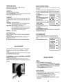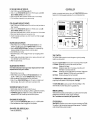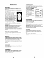
1
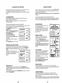
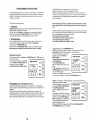
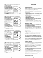
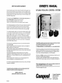
ONE YEAR LIMITED WARRANTY
Compool Corporation warrants to the purchaser of this electronic control system, for the
period of one year from the date of original purchase for use, that any defective product
proved to be caused by faulty workmanship or faulty material, will be repaired or replaced
at Compool's option for no charge, providing the product is returned to Compool with all
transportation charges prepaid.
CP-2000 POOL-SPA CONTROL SYSTEM
This warranty covers the CP-2000 Controller. LX-10 Service Center, Valve Operators, and
optional Remote Controls including all components and parts.
It does not include Sensors, batteries or labor for calib~ation.
It extends to the first retail purchaser and any subsequent owners of the system
This limited warranty applies only to controls which have been installed and maintained in
strict accordance with installation and operating instructions provided by Compool
Corporation, using installation hardware supplied and/or recommended in writing by
Compool. and to controls which have been connected to the correct supply voltage.
This limited warranty does not apply to any controls wh~chhave been repaired or altered
by anyone other than Compool or a person authorized by it: or which have been subject
to misuse, neglect or accident; or which have been damaged by wind, rain, lightning,
freezing or other cause, thing, person, or act of God; or which have been subject to
damage in transit, during installation, or by someone other than Compool Corporation; or
which have been damaged because of a defect in a component or part which is not part
of the Compool Control System: or upon which the serial number or manufacture date
has been altered, effaced or removed.
This warranty gives you specific legal rights and you may also have other rights which
vary from State to State.
Compool Corporation does not authorize any person to create any other obligation or
liability in connection with Compool controls.
Compool Corporation makes no warranty of merchantability or fitness for any use.
Any implied warranty applicable to Compool controls is limited in duration to the duration
of this written warranty.
Unless state law provides otherwise, Compool Corporation shall not be liable for
consequential or incidental damages resulting from breach of this written warranty or any
implied warranty, or for any inconvenience, loss of time. or incidental expenses such as
telephone calls.
Compool Corporation shall not be liable for any labor charges associated with the
removal or reinstallation of any so-claimed defective products.
For information on possible Authorized Service Centers within your vicinity, call Compool
Corporation at (415) 964-2201.
To exercise this warranty, send defective unit, with copy of dated receipt and a brief
description of the problems encountered, postage prepaid, to :
COMPOOL CORPORATION
599 Fairchild Drive, Mountain View. California 94043
The CP-2000 is an electronic control system which is designed to coordinate and operate
all of the equipment associated with your swimming pool and spa.
The system is comprised of three principal components :
the CP-2000 CONTROLLER, two VALVE OPERATORS, and the W-10 SERVICE CENTER.
The Controller automatically controls and monitors the timing of all your pool and spa
equipment, and the temperature of your pool and spa; the Valve Operators switch the
filter and heater from pool to spa, and activate the solar system if applicable; and the
Service Center provides easy maintenance for your Pool Serviceperson.
Additionally, the CP-2000 incorporates important safety features which protect your pool
equipment from accidental damage. (See Page 2).
Your system may also include additional Remote Controls and special options which
further add to the convenience, safety, and economy of operating your pool equipment.
Before using this electrical equipment, obtain a copy of the Installation Instructions and a
completed EQUIPMENT CHECKLIST from your Pool Builder.
Additionally, a 6-minute video (VHS fo~mat)is provided as an aid for the first-time user of
the Compool CP-2000 Control System.
&m4000/
computerized pool systems
Cornpool Corporation
599 Fairchild Drive
Mountain View
California 94043
MAINTENANCE
IMPORTANT SAFETY INSTRUCTIONS
REPLACING THE BACK-UP BATTERY :
READ AND FOLLOW ALL INSTRUCTIONS.
Basic safety precautions should always be followed when operating
and servicing this electrical equipment.
WARNING : To reduce the risk of injury, do not permit children to
use this product unless they are closely supervised at all times.
SAVE THESE INSTRUCTIONS.
There is a small 3 volt lithium battery located on the backside of the CP-2000 Controller.
In the absence of power, this battery will keep the clock running and retain the
programming in memory for approximately 48 hours.
While power is connected to the system, the battery will not be dra~ned.
However. it is not rechargeable.
To replace the battery :
1. Remove the four mounting screws from CP-2000 Controller (2 at each side)
2 Carefully fold Controller out, still connected to cable.
3. Pry-out old battery from battery clip, and replace it w ~ t ha new one.
Pay special attention to the polarity ( + sign).
The Replacement battery is available directly from Compool (model BAT-3), or can b e
purchased at Radio Shack or your local drug store. (Type CR2032, or equivalent).
CLEANING THE SPA :
SAFETY FEATURES
HEATER PROTECTION :
A built-in electronic delay c~rcuitautorr~aticallyruns the f~lterpump for an additional four
minutes whenever the system is turned off.
This feature enables the heater to cool down, so that the heat exchanger and plumbing
are not damaged from overheating.
For testing and servicing purposes, it is possible to override this delay circuit b y pushing
the DELAY CANCEL Button at the CP-2000 Controller.
POOL CLEANER PROTECTION :
If your system incorporates an automatic pool cleaner, it will have been plumbed in
conjunction with the filter pump so that it must have water circulation in order to operate.
The CP-2000 incorporates the following protection features against possible p u m p
damage if there is no water circulation:
1. Your pool cleaner will automatically be switched off whenever water is being circulated
to the Spa.
2. The filter p u m p will automatically be activated whenever the pool cleaner is running.
even if the filter p u m p has not been switched on.
3. Additionally, whenever the pool cleaner is turned on: a built-in electronic delay circuit
will prevent it from running until 4 minutes have passed. This protects the p u m p from
possible damage caused by air which may have entered the plumbing since the
system was last used.
For testing and servicing purposes, i t is possible to override this delay circuit b y
pushing the DELAY CANCEL Button at the CP-2000 Controller.
4. If your system incorporates solar, the pool cleaner will automatically be disabled for a
period of 4 minutes whenever the solar system turns on. This protects the pool
cleaner from possible damage caused by residual air within the solar panels.
BATTERY BACK-UP :
In case of a power failure, a long-life battery automatically maintains the program and
clock functions of your Control System This safeguards against the equipment
operating erratically once power has been restored, and also eliminates the need to
reprogram whenever there is a power failure
For cleaning or maintenance purposes, it is possible to use the Control System to
automatically empty your spa and then to refill with clean water from your pool.
At the LX-10 Service Center:
1. Set SYSTEM CONTROL Switch to the "SERVICE position.
2. Set FLOW CONTROL Switch to the "DRAIN' position.
3. At the MANUAL CONTROL, set FILTER Switch to the "ON" position.
4. The spa will begin to drain into the pool. Do not drain completely, or prime will be lost.
CAUTION: Do not leave equipment unattended when draining or filling the spa.
5. When cleaning is complete. set FLOW CONTROL Switch to the FILL" position.
The spa will begin to fill with clean water from the pool.
6. When the spa water level has returned to normal, return FLOW CONTROL Switch to the
"POOL" position, FILTER Switch at the MANUAL CONTROL to the "OFF" position, and
SYSTEM CONTROL Switch to the "AUTO" position.
WINTERIZING THE SYSTEM :
During the winter season, it is possible to drain your pool and disable the pool equipment
from your control system. but still be able to use your spa. Consult a qualified service
company to drain your pool and protect the plumbing from freeze damage.
The following procedure will disable the pool equipment :
1. At the LX-10 Service Center, turn SYSTEM CONTROLSwitch to the "SERVICE" position.
and FLOW CONTROL Switch to the "SPA" position.
2. Unplug cables from Valve Operators.
3. At the LX-10 Service Center, turn FLOW CONTROL Switch to the "POOL" position, and
SYSTEM CONTROL Switch to the "AUTO" position.
4. At the electrical supply panel, turn off the pool cleaner circuit breaker.
5. At the CP-2000 Controller, turn POOL Heat Select Switch to the "OFF' position.
6. If your control system incorporates solar, ensure that the panels are completely drained.
and, at the LX-10 Service Center, turn SOLAR CONTROL Switch to the "OFF" position.
If your system is equipped with Recirculating Freeze Sensors, it may not b e necessary to
drain the pool. However, it is recommended that all Freeze Sensors b e tested b y an
authorized Serviceperson before the onset of the winter season.
TEMPERATURE CONTROL :
SINGLE OCCURRENCE PROGRAM :
Separate electronic controls are provided for POOL and SPA heating.
Each control incorporates the following :
Occasionally, you may w~shto use your spa at a time which is different from your normal
daily program.
In this instance, it is poss~bleto enter a "once only" program step which will occur within
the following 24 hour period without having to reprogram the daily equipment sequence.
The "once only" program will automatically be canceled once the Clock reaches its next
program step.
I
+
Push PROGRAM Button to put the Clock into
TIME CONTROL
Program Mode.
"PROG" will appear on the right of the Display.
Continue to push PROGRAM Button until a
flashing "ONCE' appears.
Enter the time that you wish to activate the spa
Mill O U R SPA A U X I
(11:00 pm in our example) by pushing HOURS
and MINUTES Buttons.
Push SPA Equipment Button.
\
I
"ON" will appear directly above the SPA and
FILTER Buttons.
Push P R O G W Button to lock-in program.
Remember to manually turn off the spa after use, otherwise it may run all night until the
Clock reaches its next program step.
THERMOSTAT Dial :
Used to preset your desired water temperature.
As long as the Heat Select Switch is not in the "OFF' position, the water will heat up to the
preset temperature whenever the filter pump is running.
Heat Select Switch :
It is possible to heat your spa and swimming pool using solar energy, conventional heat,
or a combination of both. However, no heating will take place unless the filter pump is
running:
SOLAR Position: Allows heating with solar only.
S.PREF Position: Allows preferential heating with solar, but automatically switches to
conventional heating when solar energy is unavailable.
HEATER Position: Allows heating with gas or electric heater only.
Note: If you are heating the swimming pool (and also the spa in some
custom applications), the solar system may also contribute to the
conventional heat whenever solar energy is available.
OFF Position:
Allows no heating.
WATER TEMPERATURE Display :
Whenever the filter pump is running, the precise water temperature will be displayed in
degrees Fahrenheit.
Pool temperature will be displayed during pool circulation, and spa temperature
displayed during spa circulation.
Note: Filter pump must be running in order to provide accurate temperature display.
EIGHT PROGRAM STEPS :
If the standard six program steps are insufficient for your particular programming
requirements, it is possible to modify the Clock so that eight program steps may be
entered.
Consult the Installation Manual for details.
VALVE OPERATORS
Your control system is designed to actuate two motorized valves, which automatically
rotate between pool and spa filtration whenever the SPA Button at the CP-2OMl is
activated.
A motorized valve may also be used to automatically divert the flow of water through your
solar panels whenever solar energy is available.
These Valve Operators are also activated by the FLOW CONTROL and SOLAR CONTROL
Switches at the LX-10 Service Center.
Your system may also include additional motorized valves for custom hydraulic
applications, such as a fountain or waterfall, or (in lieu of a booster pump) to activate your
pool cleaner.
TROUBLE-SHOOTING
GENERAL :
1. Check all circuit breakers at the electrical supply panel.
2. At the LX-10 Service Center, ensure that SYSTEM CONTROL Switch is in the "AUTO
position, all MANUAL CONTROL Switches are in the "OFF" position, FLOW CONTROL
Switch is in the "POOL position, SOLAR CONTROL Switch is in the "AUTO" position,
and OUTDOOR REMOTES Switch is in the "ON" position.
NOTHING OPERATES :
1. Check 3 amp circuit breaker which is located above faceplate in LX-10 Service Center
Tripped circuit breaker is indicated by a white tab. Push to reset.
2. If circuit breaker continues to trip, refer to a qualified Service Company.
3. At the LX-10, turn OUTDOOR REMOTES Switch to the "OFF" position.
If the equipment can now be operated, there may be malfunction at your Spa-side
Remote Control.
FILTER PUMP DOES NOT OPERATE :
1. At the CP-2000, check that FILTER Status Light is ON
2. At the LX-10, turn SYSTEM CONTROL Switch to the "SERVICE" position, and FILTER
Switch at MANUAL CONTROL to the "ON' position.
3. If filter pump operates, there is a possible malfunction at the LX-10 circuit board.
4. If filter pump does not operate. pump may require servicing.
CONTROLLER
Installed in a convenient location inside your house, the CP-2000 CONTROLLER gives you
fingertip control of all the equipment associated with your swimming pool and spa.
'(;
TIME CONTROL
POOL CLEANER DOES NOT OPERATE :
CP-2000
2)
1. At the CP-2000, check that CLNR is switched ON, and that four minute "pool cleaner on
delay" has expired.
2. At the LX-10, turn SYSTEM CONTROL Switch to the "SERVICE" position, and CLNR
Switch at MANUAL CONTROL to the "ON" pos~tion.
3. If pool cleaner p u m p operates, there is a possible nlalfunction at the LX-10 circuit board
4. If pool cleaner does not operate, pump may require servicing.
5. If system incorporates a pool cleaner valve, check that cable has not been unplugged
from Valve Operator.
rllrER CLVR
$PA
AUXI
HEATER DOES NOT OPERATE :
1. At the CP-2000, make sure that POOLand SPA Heat Select Switches are in the
"HEATER" or "S. PREF" position, and that THERMOSTAT Dials are set correctly.
2. Check the WATER TEMPERATURE Display. Three dashes or an unreasonably high
temperature indicates that there is a malfunction at the Water Sensor.
3. Check that filter pump is running.
4. Check the filter pressure. If filter is clogged. the heater may not be getting sufficient
water flow.
5. Inside the heater, check pilot light and heater controls. Heater must be turned on, and
its own thermostat must be turned all the way up.
6. Heater may require servicing.
S O U R DOES NOT OPERATE :
Note: Ambient air temperature must b e approximately 5 degrees warmer than the water
temperature before the solar system is activated.
1. Check that filter p u m p is running.
2. At the CP-2000, make sure that POOLand SPA Heat Select Switches are in the
"SOLAR" or "S.PREF position, and that THERMOSTAT Dials are set correctly.
3. Check that cable has not been unplugged from Solar Valve Operator.
4. At the W-10, turn SOLAR CONTROL Switch to the " O N posit~on,and check to see if
Solar Valve rotates. Return Switch to "AUTO" position at completion of test.
SPA DOES NOT HEAT UP TO 104" F :
1. Inside the heater, check that thermostat is turned all the way up.
2. High limit control on heater may need adjusting. Refer to a qualified Service Company.
3. If HEATER Status Light at the CP-2000 turns off before spa attains the maximum
temperature of 104" F, the Controller may need a calibration adjustment.
i
--
TIME CONTROL :
The Controller houses an electronic time clock for programming the daily operating
cycles of your pool equipment.
There are four Equipment Buttons which are used for turning the equipment ON and OFF:
FILTER Button: Activates filter pump and circulates water for pool filtration.
Enables pool to be heated.
CLNR Button: Activates pool cleaner (after 4 minute delay), and also filter pump if
FILTER Button is not already switched ON.
SPA Button:
Activates filter pump and rotates valves to spa circulation. Enables spa to
be heated. Disables the CLNR Button and turns pool cleaner OFF.
AUX 1 Button: Activates auxiliary equipment (such as spa light).
The PROGRAM, HOURS and MINUTES Buttons are used for setting the Clock and for
programming the daily operation of the pool equipment. (See Page 8).
The DELAY CANCEL W o n is used to override the "Filter Pump Off Delay" or "Pool
Cleaner On Delay" circuits (for testing and servicing purposes only).
REMOTE CONTROL :
Additional remote circuits may have been added to your system to control more auxiliary
equipment (such as a pool light, air blower, jet pump, waterfall, etc.)
Note: These functions are not wntrolled b y the Programmable Clock.
SPA DRAINS OR OVERFLOWS :
1. At the W-10, check that FLOW CONTROL Switch is not in "FILL" or "DRAIN" position.
2. Check that cables have not been unplugged from Valve Operators.
SPA WATER LEVEL DROPS SLOWLY :
1. Valves may need servicing.
STATUS DISPLAY :
Status Lights are provided for the various pieces of equipment controlled by the CP-2000.
The presence of a light indicates that the equipment has been activated. The absence of
a light indicates that the equipment is turned off.
REMOTE CONTROLS
SPA-SIDE REMOTE :
One or more 4-button waterproof Remote Controls (called SUPERSWITCH) may be
located at your spa.
This will enable you to override the CP-2000 Controller, and act~vateyour spa equipment
from the convenience of the sDa. It is ~ossibleto control the followine e a u i ~ m e nfrom
t
the Spa-side Remote Control :
1. SPA Activates the filter pump, rotates valves to spa
circulation, and enables the spa to be heated.
(Overrides SPA Equipment Button at CP-2000).
2. AUX 1. Activates auxiliary equipment such as spa light.
(Overrides AUX 1 Equipment Button at CP-2000).
3. AUX2. Activates auxiliary equipment such as pool light.
(Overrides AUX 2 Equipment Button at CP-2000).
4. AUX 3. Activates auxiliary equipment such as air blower
(Overrides AUX 3 Equipment Button at CP-2000).
5. AUX 4. Activates auxiliary equipment such as jet pump.
AUX 4 cannot be controlled from the CP-2000.
If an optional Expansion Module (model MOD-BOOST) has
been installed, it is additionally possible to activate the following features from the
Spa-side Remote Control :
6. HEAT BOOST. Overrides the spa thermostat, and activates the spa heater for a five
minute period. If the filter pump is not running, t h ~ sbutton will be inactive.
7. AUX 5. Activates auxiliary equipment such as landscape lights.
8. AUX6. Activates auxiliary equipment such as a fountain. This feature is only possible
if a pool cleaner valve is used, and there is no two-speed filter pump or electric heater
being used.
A status light is located in the center of each Spa-side Remote Control.
If an optional Status Light Module (model MOD-SS4) has been installed, this light will
indicate either:
1) whenever the heater is enabled, or 2) whenever the spa is being circulated.
INDOOR REMOTE :
Your system may include a 3-button or 6-button lndoor Remote Control, which enables
you to operate the spa and auxiliary equipment from another remote location inside your
house. These lndoor Remotes include a status light for each piece of equipment.
The lndoor Remote Controls are also available with a Digital Temperature Display, which
will additionally enable you to monitor your pool and spa temperatures from a convenient
indoor location.
OUTDOOR REMOTE :
The 3-button Remote (with status lights) is also available with a hinged raintight cover for
mounting in an outdoor location.
TELEPHONE REMOTE :
If your system incorporates a Telephone Module (model MODPHONE), it is possible to
access the control system and activate the equipment from any touch-tone phone.
Consult the MOD-PHONE Manual for details.
UNUSED PROGRAM STEPS :
Our sample program utilizes all six programs steps. However your personal program
may only require that you use three or four of the available program steps. In this event,
steps.
we recommend that you disable all unused .proaram
To accomplish this, push PROGRAM Button
I
until unused program is displayed.
TIME CONTROL
Push and hold down HOURS and MINUTES
Buttons at the same time, and then release
simultaneously.
"OFF' will appear on the Display.
I
To reactivate any disabled program step,
W m I CUll SPA AUXq
simply push HOURS Button once.
"OFF' will disappear, and the Clock can then
be programmed.
.
4
4
REVIEWING PROGRAM :
After programming is complete, it is possible to rapidly advance the Clock through a 24
hour period in order to review your program.
Make sure that Clock is in Time Mode.
Push and hold down HOURS and MINUTES Buttons at the same time, and then release
simultaneously.
The Clock will rapidly advance through your program, step by step, and the appropriate
STATUS DISPLAY Lights will turn ON and OFF as each program step is activated.
When the review is complete, the Clock will automatically return to the correct time of day
and will also return all equipment to its previous status.
DELAY CANCEL:
For testing and trouble-shooting purposes, occasionally jt may be necessary to
temporarily override the built-in "Filter Pump Off Delay" or "Pool Cleaner On Delay"
circuits.
To do this, simply push the DELAY CANCEL Button.
The Delay will automatically reoccur the next time the filter pump turns off or the pool
cleaner turns on.
CUSTOM CLOCK OPTIONS
SERVICE CENTER
The standard CP-2000 Controller is provided with the appropr~ateequipment interlock
and safety delays, and enables you to enter a total of six program steps.
Your Pool Builder may, however, have incorporated one or more of the following custom
features :
Located in close proximity to your pool and spa equipment. the LX-10 SERVICE CENTER
provides your Pool Serviceperson with manual control of the system without having to
gain access to the CP-2000 Controller.
CAUTION: To prevent possible water damage, the door of the U(-10 must be kept closed
at all times.
COUNTDOWN TIMER :
Equipment Service Switches are located in the left-side compartment.
There are no user-serviceable components located behind service panel in the right-side
compartment. Do not remove service panel. Refer service to qualified personnel only.
This feature enables you to preset a 10 minute operating cycle for any piece of
equipment (FILTER, CLNR, SPA or AUX1).
Whenever that equipment is activated, it will run for 10 minutes and then it will
automatically switch off.
To better understand this feature, let us look at a typical application :
For example, we are using the AUXl circuit to activate a spa jet pump, and we would like
the jets to run for a period of 10 minutes whenever they are activated.
Push PROGRAM Button to put Clock into
I
Program Mode.
TIME CONTROL
"PROG will appear on the right of the Display.
Continue to push PROGRAM E3utton until a
flashing "TIMER' appears.
Push the MINUTES h t t o n once.
OFF OFF OFF
"0:10'will appear on the Display.
W E l C U
SPA
AUXI
Push appropriate Equipment h t t o n (AUX 1 in
our example).
"ON" will appear directly above Equipment
Button
Push PROGRAM Button to lock-in the program
SYSTEM CONTROL :
.
CTr1.n
CLM
SPA
AUX1
..,I", "0 1 1 1 1 , P I
S Y S T E M CONTROL
I W I I C " M Y I S I/I"
0,lSAll
,,o1co*,.01
.*D
IIR" C l
.OII1I"*
*.I".
L"*IIDL
,
3"
l.
I l l t 5
tOUlPMEN1 UNDER
COMPUTER CONTROL
MANUAL CONTROL :
Separate Service Switches are provided for
activating the filter pump, pool cleaner, and
auxiliary 1 circuit (lights, jet pump, etc.).
However, the SYSTEM CONTROL Switch must be
in the "SERVICE" position before these Switches
can be turned ON.
Note: Always return MANUAL CONTROL Switches
to the 'OFF position after equipment has been
serviced.
ADDITIONAL AUXILIARY CONTROL :
If your Control System does not utilize a pool cleaner, your Pool Builder may have
overridden the built-in Pool Cleaner Protection Circuits, so that the CLNR Equipment
Button can be used to activate an additional auxiliary function (such as landscape
lighting).
I
In this instance, the equipment will turn on
T l M E CONTROL
immediately (no 4 minute ON delay), and the
filter pump will not be simultaneously
activated.
This Switch should be kept in the "AUTO" position
for normal system operation.
The "SERVICE" position will disable the CP-2000
Controller and provide your Pool Serviceperson
with complete manual-override capability of all
pool equipment.
*
EOUIPMENT UNDER
MANUAL CONlPOl
I,,,,,,
B, 8"
,,.",<,
<O*ISYL
PO,
*",I
I,*"
FLOW CONTROL :
To enable this Switch, the SYSTEM CONTROL
Switch must be in the "SERVICE" position.
The "POOL and "SPA positions will automatically
rotate the motorized valves to the appropriate
water circulation.
The "FILL and "DRAIN" positions are used when
cleaning the spa. (See page 16).
Note: It is advisable to return FLOW CONTROL
Switch to 'POOL' position after use.
\
PROGRAM LOCK :
To safeguard against someone accidentally pushing the PROGRAM h t t o n and
inadvertently tampering with your daily program, your Pool Builder may have included a
Program Lock feature.
In this instance, you will need to push the PROGRAM Button quickly twice in order to put
the Clock into Program Mode.
SOLAR CONTROL :
This Switch should be kept in the "AUTO" position for normal system operation.
The "OFF and "ON" positions provide manual-override of your solar system, and should
be used for servicing and testing purposes only.
OUTDOOR REMOTES :
This Switch should be kept in the "ON' position for normal system operation.
The "OFF" position will disable any optional Remote Controls which may have been
added to your system.
This feature is particularly convenient if your system includes a Spa-side Remote Control,
and you wish to prevent the unauthorized use of your spa while you are away from home.
PROGRAMMING INSTRUCTIONS
It is possible to preset six program steps during a 24 hour period.
Each of the six steps can be used for turning equipment ON or OFF.
More than one piece of equipment can be turned ON or OFF at each program step.
However, to turn the same piece of equipment ON and OFF requires two program steps
Once the programming is complete, the pool and spa equipment will operate at the
same times every day.
The CP-2000 Controller houses a 24 hour Clock with a digital display, which can be used
to program daily pool filtration, cleaning, and other auxiliary functions such as pool and
spa lights. It can also be used to program and preheat your spa. so that it is ready for
use when you arrive home.
The Clock has two operating modes:
Before commencing programming, it is advisable to determine at what time you would
like the equipment to turn on, and for how long you would like each piece of equipment
to run.
1. TlME MODE :
In Time Mode (normal operation), the Clock will display the actual time of day, and
"TIME' will appear on the right of the Display.
While the Clock is in Time Mode, the pool equipment can be manually activated by
simply pushing the appropriate Equipment Button (FILTER, CLNR, SPA or AUXI).
This will temporarily override any preset program which may be in effect.
To better understand the programming sequence, let's follow a sample program, step by
step. For demonstration purposes, our example assumes that we would like to activate
all four pieces of equipment on a daily basis, as follows :
Filter the pool from 7:00 am until 12:00 pm.
Turn the pool cleaner on from 10:00 am until 12:00 pm.
Turn the spa on from 6:30 p m until 8:00 pm.
Turn auxiliary 1 (spa light) on from 6:30 p m to 10:00 pm.
2. PROGRAM MODE :
In order to preselect daily filtration cycles, pool cleaning, spa use, and an auxiliary
function (such as spa light), the Clock must be switched to Program Mode.
To achieve this, push PROGRAM Button once.
Whenever Clock is in Program Mode, "PROG will appear on the right of the Display.
After programming is complete, the Clock will automatically return to Time Mode.
SETTING THE CLOCK
If the Clock is not already in Time Mode, push PROGRAM Button until "TIME appears on
the right of the Display.
This indicates that the Clock is in Time Mode.
Push the HOURS and MINUTES Buttons until
A
the correct time of day is displayed
Pay special attention to the AM/PM indicator.
PROGRAMMING DAILY OPERATING CYCLES :
Programming the daily operating cycles of your pool equipment is a "set and forget"
procedure, which is normally implemented by your Pool Builder at the completion of the
installation.
Most systems only require that you program the filtration and (in some cases) the
cleaning cycles of the pool. However, it is possible to program the spa (if you plan to use
it at the same time every day), and also AUXl (if you are using this circuit to activate
lights or some other equipment which you wish to operate at the same times every day).
1
To begin programming, push PROGRAM Button once.
"PROG 1" will appear on the right of the Display. This indicates that the Clock is in
Program Mode, and that the first oroaram step
' is readv to be entered.
~ n t ethe
r first program time (7:00'amin our
#
example) by pushing the HOURS and
TlME CONTROL
MINUTES Buttons.
PROGRAM
In Program Mode, minutes are advanced in
7.)-4)-4AMPRffi
:
ten minute increments.
Push FILTER Equipment Button.
OFF OFF
" O N should appear directly above FILTER
Button.
If "ON" is displayed above any of the other
EQUIPMENT Buttons, push appropriate Button
once, and "OFF' will appear.
You have now completed the first program step.
In order to lock-in the program, simply push the PROGRAM Button once
"PROG 2" will now appear on the right of the Display. This indicates that the second
program step is ready to be entered.
#
Enter the second program time (10:OO am) by
TlME CONTROL
PRO-A"
pushing the HOURS and MINUTES Buttons.
Push CLNR Equipment Button.
" O N should appear directly above CLNR
Button.
In our example, at 10:OO am the filter pump
RLTIR C U M
SPA AUX1
should still be running. However, it will not be
necessary to push the FILTER Equipment
M o n , because the built-in protection circuit
4
will automatically activate the filter pump
whenever the pool cleaner is on.
Make sure that "OFF' is still displayed above SPA and AUXl Equipment Buttons.
Push PROGRAM Button to lock-in the program.
b
t
9
I
"PROG 3 will now appear on the r~ghtof the Display. This indicates that the third
program step is ready to be entered.
r
Enter the third program time (12:OO pm) by
TlME CONTROL
pushing the HOURS and MINUTES Buttons
Pay special attention to the AM/PM indicator.
In our example, at 12:OO pm the filter pump
and pool cleaner should turn off.
Make sure that "OFF' is displayed above each
MINUTES
FILTER CLMR
SPA A U X I
Equipment Button.
You have now completed the third program step
Push PROGRAM Button to lock-in the program.
+
SYSTEM OPTIONS
9
TWO SPEED PUMP CONTROL :
If your system incorporates a Two Speed Filter Pump, the CP-2000 has been designed to
provide you with the maximum energy-efficient usage of this feature.
I
"PROG 4 will now appear on the right of the Display. This indicates that the fourth
program step is ready to be entered.
#
Enter the fourth program time (6:30 pm) by
TlME CONTROL
pushing the HOURS and MINUTES Buttons.
In our example, at 6:30 pm the spa and
auxiliary 1 (spa light) should turn on.
Push SPA Equipment Button.
" O N should appear directly above the SPA
R U I R CUR
SPA AUXt
and FILTER Buttons.
Push AUXl Equipment Button.
"ON' should appear above AUXl Button
You have now completed the fourth program
step.
Push PROGRAM Button to lock-in the program.
"PROG 5" will now appear on the right of the Display. This indicates that the fifth
program step is ready to be entered.
#
Enter the fifth program time (8:OO pm) by
TlME CONTROL
pushing the HOURS and MINUTES Buttons.
In our example, we would like to turn off the
spa at 8:00 pm, but the spa light (AUX 1)
should still be on.
CfF
OFF OFF
Push AUX 1 Equipment Button.
RLTSR CLWR
SPA A U X I
"ON" will appear above AUXl Button.
You have now completed the fifth program step.
Push PROGRAM Button to lock in the program
4
SPA WATERFALL CONTROL :
I
9
.
"PROG 6 will now appear on the right of the Display. This indicates that the sixth
program step is ready to be entered.
Enter the sixth program time (10:OO pm) by
TIME CONTROL
pushing the HOURS and MINUTES Buttons.
In our example, all of the equipment should be
turned off at 10:OO pm.
Therefore, make sure that "OFF' is displayed
above all of the Equipment Buttons.
R U I I CU
SPA AUX1
To lock-in the program and return Clock to
Time Mode, simply push the PROGRAM
Button once.
If this is forgotten, the Clock will automatically \
return to Time Mode after two minutes.
If your spa water level is elevated above that of the pool, your Pool Builder may have
included a Spa Waterfall Control (model RLY-WRFL).
With this feature, you can circulate the pool water back to the spa, creating an overflow
(waterfall effect) from the spa to the pool. This effect will cease during spa circulation.
Depending upon which circuit has been used to connect the Spa Waterfall Control, either
the AUX1. AUX2 or AUX3 Button will activate this feature.
FREEZE PROTECTION :
Recirculating Freeze Sensors (model FPSC) may have been added to your system.
These Sensors protect the plumbing and equipment from possible freeze damage by
running the filter pump whenever the temperature falls to approximately 41" F.
Similarly, Auxiliary Pump Freeze Sensors (model FPSAUX) may have been added to
activate auxiliary equipment (such as a fountain or jet pump) during freezing conditions.
---•
.
Although your Pool Builder may have adjusted the two speed control circuitry to your
specific requirements, the CP-2000 typically switches the pump to high speed under any
of the following conditions:
1. For two minutes when the filter is first turned on. This features establishes proper flow
through the system, and packs the filter grids. After two minutes, the pump will
automatically switch to low speed.
2. Whenever the pool cleaner is running. This provides sufficient flow for the pool
cleaner to operate effectively.
3. During spa operation to increase the jet action.
4. Whenever the heater is on. This feature will conserve energy by bringing your pool
and spa up to the desired temperature more quickly.
5. Whenever your solar system is operating. This provides high flow rate through your
solar panels, which ensures the most efficient usage of the available solar energy.
CAUTION : Freeze Sensors will not provide circulation of water through your solar panels.
Solar freeze protection must be accomplished by draining the panels. (See below).
I
SOLAR PANEL DRAINDOWN :
9
If your control system incorporates solar heating, it is advisable that a draindown feature
be included to protect the solar panels against potential freeze damage.
For conventional solar systems which permit gravity drainage of panels, the Compool
Solar Valve with built-in check valve (model SOL-2T) will automatically drain the panels
whenever the solar turns off and the filter pump is not running.
I
For solar systems with glazed panels. damage can occur from overheating if the solar
turns off and the filter pumw is still running.
In this instance, a motorized Draindown Valve (model HW-5B) should be plumbed at the
solar feed line. This will automatically drain the panels whenever the solar is turned off,
even if the filter pump is still running.
This feature may also be incorporated if your solar system does not facilitate gravity
drainage of panels, or where panels are located below pool water level.
Consult your Solar Company for more details.