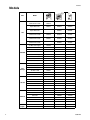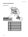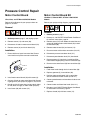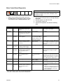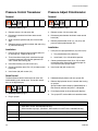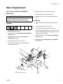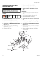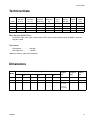
1
Repair
Electric Airless Sprayers
309674M
- For the application of architectural paints and coatings Important Safety Instructions. Read all warnings and instructions
in this manual. Save these instructions. See page 2 for model
information.
3300 psi (227 bar, 22.7 MPa) Maximum Working Pressure
Korean patent: 10-0579681
WLD
ti2399
UltraTM 395/495/595
Ultimate NovaTM 395
Super NovaTM 495/595
ST MaxTM 395/495/595
Graco Inc. P.O. Box 1441 Minneapolis, MN 55440-1441
Copyright 2002, Graco Inc. is registered to I.S. EN ISO 9001
UltraMax IITM 490/495/595
Ultimate MX IITM 490/495/595
ST Max IITM 490/495/595
Models
Models
VAC
120
Model
Ultra 395
Ultimate Nova 395
233960
826014
233961
233962
Ultra 495
Super Nova 495
233966
826017
233967
826018
233968
826019
234490
826052
234435
826046
Ultra 595
Super Nova 595
Ultra Max II 490
Ultimate MX II 490
249911
825028
249913
825029
249914
825036
Ultra Max II 495
Ultimate MX II 495
249915
825037
249916
825038
249917
825039
249918
825046
249919
825045
Ultra Max II 595
Ultimate MX II 595
230 CEE
ST Max 395 Hopper
233955
ST Max 395
234176
258662
ST Max 495
233956
233970
233971
248661
244437
ST Max 595
ST Max II 490 Hopper
253011
ST Max II 490
249926
253012
253013
ST Max II 495
249928
253014
249978
253015
249930
ST Max II 595
230
Europe
ST Max 395
223963
ST Max 495
233957
233975
ST Max 595
244436
ST Max II 490
249927
ST Max II 495
249929
249979
ST Max II 595
110 UK
249931
ST Max 395
223972
ST Max 495
233973
233975
ST Max 595
244436
ST Max II 490
249935
ST Max II 495
249936
249980
ST Max II 595
230 Asia
249937
Ultra 395
234180
Ultra 495
234183
Ultra 595
Ultra Max II 490
249932
Ultra Max II 495
249933
Ultra Max II 595
100
Japan
2
234181
234182
248660
244439
253104
253105
253107
249934
Ultra 495
234186
233974
UltraMax II 495
249938
253106
309674M
Warnings
Warnings
The following are general warnings related to the setup, use, grounding, maintenance, and repair of this equipment.
Additional, more specific warnings may be found throughout the body of this manual where applicable. Symbols
appearing in the body of the manual refer to these general warnings. When these symbols appear throughout the
manual, refer back to these pages for a description of the specific hazard.
WARNING
FIRE AND EXPLOSION HAZARD
Flammable fumes, such as solvent and paint fumes, in work area can ignite or explode. To help prevent
fire and explosion:
• Use equipment only in well ventilated area.
• Eliminate all ignition sources; such as pilot lights, cigarettes, portable electric lamps, and plastic drop
cloths (potential static arc).
• Sprayer generates sparks. When flammable liquid is used in or near the sprayer or for flushing or
cleaning, keep sprayer at least 20 feet (6 m) away from explosive vapors.
• Keep work area free of debris, including solvent, rags, and gasoline.
• Do not plug or unplug power cords or turn lights on or off when flammable fumes are present.
• Ground equipment and conductive objects in work area. Read Grounding instructions.
• If there is static sparking or you feel a shock, stop operation immediately. Do not use equipment
until you identify and correct the problem.
• Keep a fire extinguisher in the work area.
ELECTRIC SHOCK HAZARD
Improper grounding, setup, or usage of the system can cause electric shock.
• Turn off and disconnect power cord before servicing equipment.
• Use only grounded electrical outlets.
• Use only 3-wire extension cords.
• Ensure ground prongs are intact on sprayer and extension cords.
• Do not expose to rain. Store indoors.
SKIN INJECTION HAZARD
High-pressure fluid from gun, hose leaks, or ruptured components will pierce skin. This may look like just
a cut, but it is a serious injury that can result in amputation. Get immediate surgical treatment.
• Do not point gun at anyone or at any part of the body.
• Do not put your hand over the spray tip.
• Do not stop or deflect leaks with your hand, body, glove, or rag.
• Engage trigger lock when not spraying.
• Follow Pressure Relief Procedure in this manual, when you stop spraying and before cleaning,
checking, or servicing equipment.
309674M
3
Warnings
EQUIPMENT MISUSE HAZARD
Misuse can cause death or serious injury.
• Do not exceed the maximum working pressure or temperature rating of the lowest rated system
component. Read Technical Data in all equipment manuals.
• Use fluids and solvents that are compatible with equipment wetted parts. Read Technical Data in all
equipment manuals. Read fluid and solvent manufacturer’s warnings. For complete information
about your material, request MSDS from distributor or retailer.
• Check equipment daily. Repair or replace worn or damaged parts immediately with genuine Graco
replacement parts only.
• Do not alter or modify equipment.
• Use equipment only for its intended purpose. Call your Graco distributor for information.
• Route hoses and cables away from traffic areas, sharp edges, moving parts, and hot surfaces.
• Do not kink or overbend hoses or use hoses to pull equipment.
• Comply with all applicable safety regulations.
• Keep children and animals away from work area.
• Do not operate the unit when fatigued or under the influence of drugs or alcohol.
PRESSURIZED ALUMINUM PARTS HAZARD
Do not use 1,1,1-trichloroethane, methylene chloride, and/or other halogenated hydrocarbon solvents or
fluids containing such solvents in pressurized aluminum equipment. Such use can cause serious chemical reaction and equipment rupture, and result in death, serious injury, and/or property damage.
TOXIC FLUID OR FUMES HAZARD
Toxic fluids or fumes can cause serious injury or death if splashed in the eyes or on skin, inhaled, or
swallowed.
• Read MSDS’s to know the specific hazards of the fluids you are using.
• Store hazardous fluid in approved containers and dispose of it according to applicable guidelines.
PERSONAL PROTECTIVE EQUIPMENT
You must wear appropriate protective equipment when operating, servicing, or when in the operating
area of the equipment to help protect you from serious injury, including eye injury, inhalation of toxic
fumes, burns, and hearing loss. This equipment includes, but is not limited to:
• Protective eye wear
• Clothing and respirator as recommended by the fluid and solvent manufacturer
• Gloves
• Hearing protection
4
309674M
Component Identification
Component Identification
Model 233960 shown
4
5
3
2
1
7
9
8
6
B
FN
309674M
Component
1
ON/OFF switch
2
Prime tube
3
Siphon tube
4
Pressure control
5
Filter
6
Trigger lock
7
Pump
8
Fluid outlet
9
Prime/Spray valve
10
Service Tag (below sprayer frame)
5
Installation
Installation
Grounding and Electric
Requirements
Power Requirements
The sprayer must be grounded. Grounding reduces the
risk of static and electric shock by providing an escape
wire for the electrical current due to static build up or in
the event of a short circuit.
The sprayer power cord includes a grounding wire with
an appropriate grounding contact.
•
100-120V units require 100-120VAC, 50/60 Hz,
15A, 1 phase
•
230V units require 230VAC, 50/60 Hz, 7.5A, 1
phase
•
Never use an outlet that is not grounded or an
adapter.
Only use an extension cord with an undamaged
ground contact. If an extension cord is necessary, use a
3-wire, 12 AWG (2.5 mm2) minimum.
Smaller gauge or longer extension cords may
reduce sprayer performance.
Spray gun: ground through connection to a properly
grounded fluid hose and pump.
Fluid supply container: follow local code.
The plug must be plugged into an outlet that is properly
installed and grounded in accordance with all local
codes and ordinances. Do not use an adapter.
Solvent and oil-based fluids: follow local code. Use
only conductive metal pails, placed on a grounded surface such as concrete.
Do not place the pail on a nonconductive surface, such
as paper or cardboard, which interrupts grounding continuity.
Grounding the metal pail: connect a ground wire to the
pail by clamping one end to pail and other end to ground
such as a water pipe.
TIC
Do not use the sprayer if the electrical cord has a damaged ground prong. Do not modify plug. If it will not fit in
outlet, have a grounded outlet installed by a qualified
electrician.
6
Maintain grounding continuity when flushing or
relieving pressure: hold metal part of the spray gun
firmly to the side of a grounded metal pail, then trigger
the gun.
309674M
Operation
Operation
Pressure Relief Procedure
To reduce risk of injury from injection, follow this procedure whenever you are instructed to relieve pressure,
stop spraying, service equipment or install or clean
spray tip. Read warnings, page 3.
2. Turn pressure to lowest setting. Hold gun to side of
grounded metal flushing bucket. Trigger gun to
relieve pressure, turn prime valve down.
-
ti2
ti2599a
1. Turn power switch OFF and unplug power cord.
\
ti2614a
FLUSH
3. Engage gun trigger lock if unit is being shut down or
left unattended.
ti2718a
Leave Spray - Prime/Drain valve in the
PRIME/DRAIN position until you are ready to spray
again.
ti2707a
If you suspect the spray tip or hose is clogged or that
pressure has not been fully relieved after following the
steps above, VERY SLOWLY loosen tip guard retaining
nut or hose end coupling to relieve pressure gradually,
then loosen completely. Clear hose or tip obstruction.
309674M
7
General Repair Information
General Repair Information
Flammable materials spilled on hot, bare motor could
cause fire or explosion. To reduce risk of burns, fire or
explosion, do not operate sprayer with cover removed.
CAUTION
To reduce risk of pressure control malfunction:
•
Use needle nose pliers to disconnect wire. Never
pull on wire, pull on connector.
•
Mate wire connectors properly. Center flat blade
of insulated male connector in female connector.
•
Route wires carefully to avoid interference with
other connections or pressure control. Do not
pinch wires between cover and control box.
To reduce risk of serious injury, including electric shock:
•
Do not touch moving or electric parts with fingers or
tools while testing repair.
•
Unplug sprayer when power is not required for testing.
•
Install all covers, gaskets, screws and washers
before you operate sprayer.
•
•
Keep all screws, nuts, washers, gaskets, and electrical fittings removed during repair procedures. These
parts usually are not provided with replacement kits.
•
Test repairs after problems are corrected.
•
If sprayer does not operate properly, review repair
procedure to verify you did it correctly. See Troubleshooting, page 9.
•
Install motor shroud before operation of sprayer and
replace if damaged. Motor shroud directs cooling air
around motor to prevent overheating. It can reduce
risk of burns, fire or explosion, or cut fingers.
8
CAUTION
Do not run sprayer dry for more than 30 seconds.
Doing so could damage pump packings.
•
Protect the internal drive parts of this sprayer from
water. Openings in the cover allow for air cooling of
the mechanical parts and electronics inside. If
water gets in these openings, the sprayer could
malfunction or be permanently damaged.
•
Prevent pump corrosion and damage from freezing.
Never leave water or water-base paint in sprayer
when its not in use in cold weather. Freezing fluids
can seriously damage sprayer. Store sprayer with
Pump Armor to protect sprayer during storage.
309674M
Troubleshooting
Troubleshooting
Type of Problem
Basic fluid pressure problems
Basic Mechanical Problems
What to Check
(if check is OK, go to next)
What to Do
(When check is not OK, refer to this
column)
Pressure control knob setting. Motor Slowly increase pressure to see if
will not run if at minimum setting (fully motor starts.
counter-clockwise).
Spray tip or fluid filter may be
clogged.
Relieve pressure, page 7 and clear
clog, or clean filter; refer to separate
gun or tip instruction manual.
Pump frozen or paint hardened in
pump.
Thaw sprayer if water or water-based
paint has frozen in sprayer. Place
sprayer in warm area to thaw. Do not
start sprayer until thawed completely.
If paint hardened (dried) in sprayer,
replace pump packings. See page
15, Displacement Pump Replacement.
Displacement pump connecting rod Push pin into place and secure with
pin must be completely pushed into spring retainer.
connecting rod and retaining spring
must be firmly in groove of pump pin.
See page 15.
Motor. Remove drive housing assem- Replace motor if fan won’t turn. See
bly. See page 17. Try to rotate fan by page 19.
hand.
Motor control board. Board shuts
down and displays error code.
309674M
See Motor Control Board Diagnostics, page 27.
9
Troubleshooting
What to Check
(if check is OK, go to next)
Type of Problem
Basic Electrical Problems
Electric supply. Meter must read:
•
•
210-255 VAC for 220-240V
models
85-130 VAC for 100-120V
models.
What to Do
(When check is not OK, refer to this
column)
Reset building circuit breaker.
Replace building fuse. Try another
outlet.
Extension cord. Check extension
cord continuity with volt meter.
Replace extension cord.
Sprayer power supply cord. Inspect
for damage such as insulation or
wires.
Replace power supply cord, page 24.
Motor leads are securely fastened
and properly mated.
Replace loose terminals; crimp to
leads. Be sure terminals are firmly
connected.
Clean circuit board terminals.
Securely reconnect leads.
Basic Electrical Problems - These
problems only apply to Ultra, Nova
and STMax 395/495/595 model
sprayers with brush motors. They do
not apply to UltraMax II, Ultimate
MX II and ST Max II 490/495/595
model sprayers.
Motor armature for shorts using
armature tester (growler) or perform
spin test. See page 18.
Replace motor. See page 29.
For loose motor brush lead connections and terminals.
Tighten terminal screws. Replace
brushes if leads are damaged.
Brush length which must be 1/2 in.
minimum. NOTE: Brushes do not
wear at the same rate on both sides
of motor. Check both brushes.
Replace brushes, page 20.
Broken or misaligned motor brush
Replace spring if broken. Realign
springs. Rolled portion of spring must spring with brush.
rest squarely on top of brush.
Motor brushes may be binding in
brush holders.
Clean brush holders. Remove carbon
with small cleaning brush. Align
brush leads with slot in brush holder
to assure free vertical brush movement.
Motor armature commutator for burn Remove motor and have motor shop
spots, gouges or extreme roughness. resurface commutator if possible.
See page 29.
10
309674M
Troubleshooting
What to Check
(if check is OK, go to next)
Type of Problem
Note: for the following electric problems, refer to wiring diagram, page
22, 23, and 24 to identify Test Points
(TP).
Power supply cord. Connect volt
meter between TP1 (neutral) and
TP2. Plug in sprayer. Meter must
read:
•
•
What to Do
(When check is not OK, refer to this
column)
Replace power supply cord, page 24.
210-255 VAC for 220-240V
models
85-130 VAC for 100-120V
models.
Unplug sprayer.
ON/OFF Switch. Connect volt meter
between L1 and L2 terminal on
ON/OFF switch. Plug in sprayer and
turn ON. Meter must read:
•
•
Low Output
Replace ON/OFF switch. See page
22.
210-255 VAC for 220-240V
models
85-130 VAC for 100-120V
models.
All terminals for damage or loose fit.
Replace damaged terminals and
reconnect securely.
For worn spray tip.
Relieve pressure, page 7. Then
replace tip. See your separate gun
manual for additional instruction.
Verify pump does not continue to
stroke when gun trigger is released.
Service pump. See page 15.
Filter clogged.
Relieve pressure, page 7. Check
and clean filter.
Prime valve leaking.
Relieve pressure, page 7. Repair
prime valve.
Suction hose kinks and/or loose
connection.
Correct kink and/or tighten any loose
connections.
Electric supply with volt meter. Low
voltages reduce sprayer
performance. Meter must read:
Reset building circuit breaker;
replace building fuse. Repair
electrical outlet or try another outlet.
•
•
210-255 VAC for 220-240V
models
85-130 VAC for 100-120V
models.
Extension cord size and length; must Replace with a correct, grounded,
extension cord.
be at least 12 gauge wire and no
longer than 300 ft. Longer cord
lengths reduce sprayer performance.
309674M
11
Troubleshooting
Type of Problem
Low Output
What to Check
(if check is OK, go to next)
What to Do
(When check is not OK, refer to this
column)
Leads from motor to pressure control
circuit board for damaged or loose
wires or connectors. Inspect wiring
insulation and terminals for signs of
overheating.
Be sure male terminal blades are
centered and firmly connected to
female terminals. Replace any loose
terminal or damaged wiring. Securely
reconnect terminals.
Low stall pressure.
Do either or both:
a. Turn pressure control knob
fully clockwise. Make sure
pressure control knob is
properly installed to allow full
clockwise position.
b. Try a new transducer.
These problems only apply to Ultra,
Nova and STMax 395/495/595
model sprayers with brush motors.
They do not apply to UltraMax II,
Ultimate MX II and ST Max II
490/495/595 model sprayers.
Motor armature for shorts by using an Replace motor. See page 29.
armature tester (growler) or perform
spin test. See page 18.
Loose motor brushes and terminals.
Tighten terminal screws. Replace
brushes if leads are damaged.
Worn motor brushes. (Brushes must
be 1/2 in. minimum.)
Replace brushes.
Broken and misaligned motor brush Replace spring if broken. Realign
springs. Rolled portion of spring must spring with brush.
rest squarely on top of brush.
Motor brushes are binding in brush
holders.
Motor runs and pump strokes
Clean brush holders, remove carbon
dust with small cleaning brush. Align
brush lead with slot in brush holder
to assure free vertical brush
movement.
Low paint supply.
Refill and reprime pump.
Intake strainer clogged.
Remove and clean, then reinstall.
Suction tube or fittings loose.
Tighten; use thread sealant or
sealing tape on threads if necessary.
See if intake valve ball and piston ball Remove intake valve and clean.
Check balls and seats for nicks,
are seating properly. See pump
manual.
replace if necessary. Strain paint
before using to remove particles that
could clog pump. See pump manual.
Leaking around throat packing nut
Replace packings. Also check piston
which may indicate worn or damaged valve seat for hardened paint or nicks
and replace if necessary. Tighten
packings. See pump manual.
packing nut/wet-cup. See pump
manual.
Pump rod damage.
12
Replace pump, page 15.
309674M
Troubleshooting
Type of Problem
What to Check
(if check is OK, go to next)
Motor runs but pump does not stroke Displacement pump pin damaged or
missing.
Motor is hot and runs intermittently
Building circuit breaker opens as
soon as sprayer switch is turned on
CAUTION
Any short in any part of the motor
power circuit will cause the control
circuit to inhibit sprayer operation.
Correctly diagnose and repair all
shorts before checking and replacing
control board.
What to Do
(When check is not OK, refer to this
column)
Replace pump pin if missing. Be sure
retainer spring is fully in groove all
around connecting rod, page 15.
Connecting rod assembly damaged.
Replace connecting rod assembly.
See pump manual.
Gears or drive housing, page 17.
Inspect drive housing assembly and
gears for damage and replace if
necessary, page 17.
Determine if sprayer was operated at Decrease pressure setting or
high pressure with small tips, which increase tip size.
causes low motor RPM and
excessive heat buildup.
Be sure ambient temperature where
sprayer is located is not more than
90°F (32.22°C) and sprayer is not
located in direct sun.
Move sprayer to shaded, cooler area
if possible.
All electrical wiring for damaged
insulation and all terminals for loose
fit or damage. Also, wires between
pressure control and motor. See
page 28.
Repair or replace any damaged
wiring or terminals. Securely
reconnect all wires.
For missing inspection plate gasket,
see page 26, bent terminal forks or
other metal to metal contact points
which case a short.
Correct faulty conditions.
Motor control board by performing
control board diagnostics. See page
14. If diagnostics indicate, substitute
with a good board.
Replace with a new pressure control
board. See page 26.
CAUTION: Do not perform this check
until motor armature is determined to
be good. A bad motor armature can
burn out a good board.
Building circuit breaker opens as
soon as sprayer switch is turned on
This problem only applies to Ultra,
Nova and STMax 395/495/595
model sprayers with brush motors.
They do not apply to UltraMax II,
Ultimate MX II and ST Max II
490/495/595 model sprayers.
Motor armature for shorts. Use an
armature tester (growler) or perform
spin test. See page14. Inspect
windings for burns.
Building circuit breaker opens as
Basic Electric Problems, page 9 of
soon as sprayer is plugged into outlet Troubleshooting.
and sprayer is NOT turned on.
309674M
Replace motor. See page 29.
Perform necessary procedures.
13
Troubleshooting
What to Check
(if check is OK, go to next)
Type of Problem
What to Do
(When check is not OK, refer to this
column)
Replace ON/OFF switch. See page
ON/OFF switch. See page 22. Be
22.
sure sprayer is unplugged!
Disconnect wires from switch. Check
switch with ohmmeter. Reading must
be infinity with ON/OFF switch OFF,
and zero when switch is ON.
Sprayer quits after sprayer operates
for 5 to 10 minutes.
For damaged or pinched wires in
pressure control. See page 26.
Replace damaged parts. See page
26.
Basic Electric Problems, page 9 of
Troubleshooting.
Perform necessary procedures.
Electrical supply volt meter. Meter
must read:
If voltage is too high, do not operate
sprayer until corrected.
•
•
210-255 VAC for 220-240V
models
85-130 VAC for 100-120V
models.
Tightness of pump packing nut. Over
tightening tightens packings on rod,
restricts pump action, and overloads
motor.
14
Loosen packing nut. Check for
leaking around throat. Replace pump
packings, if necessary. See pump
manual.
309674M
Displacement Pump Replacement
Displacement Pump Replacement
See manual 309053 for pump repair instructions.
4. Cycle motor until pump pin (32)is in position to be
removed.
Removal
1. Flush pump (13).
1. Relieve pressure, page 7.
2. (Style A) Loosen screws (12) and rotate cover (70).
Note: Style A is shown in most illustrations.
WLD
32
5. Disconnect power cord from outlet.
(Style B) Loosen screws (12). Push cover (70) up
and pull off sprayer.
6. Using a flat screwdriver, push retaining spring (31)
up. Push out pump pin (32).
Style B
Style A
31
12
70
70
32
3. Remove suction tube (60) and hose (45).
7. Loosen pump jam nut (29). Unscrew and remove
pump (41).
29
45
12
41
TIA
60
309674M
15
Displacement Pump Replacement
Installation
5. Screw in pump until threads are flush with top of
drive housing opening.
WARNING
If pump pin works loose, parts could break off due to
force of pumping action. Parts could project through
air and result in serious injury or property damage.
CAUTION
If the pump jam nut loosens during operation, the
threads of the drive housing will be damaged.
6. Align pump outlet to back.
1. Extend pump piston rod full. Apply grease to top of
pump rod at (A) or inside connecting rod (43). Install
jam nut (29) on pump threads.
29
WLD
7. Turn jam nut (29) counter-clockwise until it stops.
Tighten jam nut by hand, then tap 1/8 to 1/4 turn
with a 20 oz (maximum) hammer to approximately
75 ft-lb (102 N•m).
A
8. Install suction tube (60) and high pressure hose
(45). Tighten fittings.
.
WLD
2. Install pump rod (A) into connecting rod (43).
45
43
A
29
TIA
60
9. Fill packing nut with Graco TSL until fluid flows onto
top of seal.
3. Install pump pin (32). Slide retainer spring (31)
down into groove over pump pin.
31
12
70
WLD
10. (Style A) Rotate cover (70). Tighten screws (12).
32
4. Push pump (41) up until pump threads engage.
16
(Style B) Replace cover (70) over screws. Push
cover down into place. Tighten screws (12).
309674M
Drive Housing Replacement
Drive Housing Replacement
3. Remove screws (12) and pump rod cover (70).
CAUTION
Do not drop gear cluster (44) and (40) when removing
from drive housing (42). Gear cluster may stay
engaged in motor front end bell or drive housing.
4. Remove pump (41), Displacement Pump Replacement, page 15
5. Remove screws (12) from shroud (23).
Removal
6. Remove screws (12) from front cover (22).
7. Remove screws (47).
8. Pull drive housing (42) off motor (54).
9. Remove gear cluster (44) and (40) and thrust
washer (25) from drive housing.
1. Relieve pressure, page 7.
2. Disconnect power cord from outlet.
!
TIC
Installation
1. Apply a heavy coat of grease to gears and needle
bearing surfaces.
2. Install washers (8, 10) on back of gear (40). Install
gear in motor end bell. Using grease for retention,
place washer (10) over bearing inside housing (42).
5. Push drive housing (42) on motor endbell as you
guide gear crank (44) through hole in connecting
rod (43).
6. Install screws (47).
7. Install cover (22) and screws (12).
8. Install shroud (23) and screws (12).
3. Install washers (1, 9) on back of gear (44). Install in
motor endbell.
9. Install pump (41); Displacement Pump Replacement, page 15.
4. Install thrust washer (25) on gear (44).
10. Install pump rod cover (70) with screws (12).
309674M
17
Motor Diagnostics
Motor Diagnostics
Spin Test
*Note: Motors used in the UltraMax II, Ultimate MX II and ST Max II 490/495/595 model sprayers are brushless. The
following brush information and instructions apply to Ultra, Nova and ST Max 395/495/595 model sprayers only.
Check for electrical continuity in motor armature, windings and brush* as follows:
If Motor Diagnostics reveal a damaged motor or if motor brushes* are shorter than 1/2 in. (12.7 mm) or if the motor
shaft cannot turn, replace the motor, page 29.
Setup
1. Relieve pressure, page 7.
Armature, Brushes and Motor Wiring Open Circuit
Test (Continuity)
1. Connect red and black motor leads together with
test lead.
2. Unplug electric cord.
3. Remove drive housing, Drive Housing Replacement, page 17.
4. Remove pressure control cover (50). Disconnect
connector F.
5. Remove four screws (12) and motor shroud (23)
and inspection covers.
2. Turn motor fan by hand, about two revolutions per
second.
3. If there is an uneven resistance or no resistance,
check for broken brush springs*, brush leads*; loose
brush terminal screws*, worn brushes*, or motor
lead terminals. Repair as needed, page 20.
4. If still uneven, or no resistance, replace motor using
Motor Kit, page 29.
Armature Short Circuit Test
Quickly turn motor fan by hand. If not shorted, motor will
coast two or three revolutions before complete stop. If
motor does not spin freely, armature is shorted. Replace
motor, page 29.
F
WLD
50
18
309674M
Fan Replacement
Fan Replacement
Removal
4. Pull off fan (77).
Installation
1. Relieve pressure, page 7. Disconnect power cord
from outlet.
1. Slide new fan (125) in place on back of motor. Be
sure blades of fan face motor as shown.
2. Tighten screw (126).
2. Remove four screws (12) and shroud (23).
3. Replace shroud (23) and four screws (12).
3. Loosen tensioning screw (126) on fan (125).
12
23
125
126
TIA
309674M
19
Motor Brush Replacement
Motor Brush Replacement
Note: Motors used in the UltraMax II, Ultimate MX II and ST Max II 490/495/595 model sprayers are brushless. The
following brush information and instructions apply to Ultra, Nova and ST Max 395/495/595 model sprayers only.
The Utlra, Nova and ST Max 395/495/595 sprayer’s motors are supplied by two different motor manufacturers. Style
A motor has brush caps held on with screws. Style B has brush caps that snap onto the motor. Determine which style
motor you are servicing and refer to the appropriate illustration in the following instructions.
Motor Brush Removal
Included in Brush Repair Kit
Replace brushes worn to less than 1/2 in. Brushes wear
differently on each side of motor, check both sides.
Brush Repair Kit 287735 is available.
B
1. Read General Repair Information, page 8.
D
G
Minimum 0.5 in. (12.5 mm)
C
F
2. Relieve pressure, page 7.
WLD
E
Style A
3. Remove motor shroud and two inspection covers
(A).
5. Pull brush lead (E) off terminal (F). Remove brush
(G).
Style A
Motor lead; do not disconnect
Minimum 0.5 in. (12.5 mm)
Included in Brush Repair Kit
C
D
E
WLD
A
Style B
WLD
F
B
WLD
4. Push clip spring (B) to release hook (C) from brush
holder (D). Pull out spring clip (B).
20
G
Style B
6. Inspect commutator for excessive pitting, burning, or
gouging. A black color on commutator is normal.
Have commutator resurfaced by a motor repair shop
if brushes wear too fast.
309674M
Motor Brush Replacement
Motor Brush Installation
CAUTION
When installing brushes, follow all steps carefully to
avoid damaging parts.
Style A
Style B
G
D
C
D
B
WLD
E
F
1. Install new brush (G) with lead into brush holder (D).
B
WLD
E
c.
2. Slide brush lead (E) onto terminal (F).
3. Install spring clip (B). Push down to set hook (C) into
brush holder (D).
4. Repeat for other side.
F
G
Turn sprayer ON. Slowly increase pressure until
motor is at full speed.
CAUTION
Do not run sprayer dry for more than 30 seconds
while checking brushes to avoid damaging displacement pump packings.
5. Test brushes.
a. Remove pump. Displacement Pump Replacement, page 15.
b.
With sprayer OFF, turn pressure control knob
fully counter-clockwise to minimum pressure.
Plug in sprayer.
309674M
6. Install brush inspection covers (A) and gaskets.
7. Break in brushes.
a. Operate sprayer 1 hour with no load.
b.
Install pump. Displacement Pump Replacement, page 15.
21
On/Off Switch Replacement
On/Off Switch Replacement
100/120 VAC Ultra and ST 395/495/595 models
Removal
4. Remove toggle boot (30) and locking ring. Remove
ON/OFF switch (58).
Installation
1. Install new ON/OFF switch (58). Install locking ring
and toggle boot (30).
1. Relieve pressure, page 7.
2. Connect two wires (A) to ON/OFF switch (58).
2. Remove four screws (12) and pressure control cover
(50).
3. Install pressure control cover (50) with four screws
(12).
3. Disconnect two wires (A) from ON/OFF switch (58).
D
$
'
(
:LULQJ'LDJUDP
WLE
'RPHVWLF
%ODFN
212))
6ZLWFK
3RZHU3OXJ
%ODFN
TP1/L1
L2
J8
TP2
%ODFN
:KLWH
3RWHQWLRPHWHU
*UHHQ
J7
5HG
%ODFN
WL
IURP0RWRU
[:KLWH
22
309674M
On/Off Switch Replacement
110/240 VAC Ultra, Nova, and ST Max 395/495/595 models
5. Remove toggle boot (30) and locking ring. Remove
ON/OFF switch (58).
Installation
Removal
1. Install new ON/OFF switch (58). Install locking ring
and toggle boot (30).
1. Relieve pressure, page 7.
2. Remove four screws (12) and pressure control cover
(50).
3. Remove display connector (B) from plug (C).
4. Disconnect four wires (A) from ON/OFF switch (58).
2. Connect four wires (A) to ON/OFF switch (58).
3. Install display connector (B) to plug (C).
4. Install pressure control cover (50) with four screws
(12).
A
!
$ %
#
"
TIB
"LACK
/./&&
3WITCH
"LUE
40
4O0OWER
0LUG
0OTENTIOMETER
J8
40
"ROWN
)NDUCTOR#OIL
"LUE
"LACK
4RANSDUCER
&ILTER"OARD
'REEN
"ROWN
J7
2ED
"LACK
WHITE
, ,
&ROM-OTOR
TIB
X7HITE
$IGITAL$ISPLAY
309674M
23
On/Off Switch Replacement
UltraMax II, Ultimate MX II and ST Max II 490/495/595 models
ON/OFF Switch/Power Cord Board Kit
8. Disconnect black lead between control boards.
9. Remove switch board from box.
Installation
Removal
1. Reconnect black lead between control and switch
boards.
1. Relieve pressure, page 7.
2. Remove four screws (12) and control box cover (50).
Power Cord
2. Slide ON/OFF switch (30) through opening in control box housing and position switch board.
3. Remove green ground screw (19) and disconnect
ground choke coil and black leads.
3. Place toggle boot (58) over ON/OFF switch. Using a
5/8 in. deep socket wrench, tighten securely.
4. Slide black power cord strain relief (a) out of slot in
control box (48) to remove it.
4. Install switchboard mounting screws (6).
On/Off Switch
5. Slide power cord strain relief (a) into opening in control box (48).
6. Reattach black and white power cord leads to control and switch boards.
5. Remove switchboard mounting screw (6)
6. Using a 5/8 in. deep socket wrench, remove
ON/OFF switch toggle boot (58).
7. Reattach ground choke coil to ground screw (19).
Replace and tighten green ground screw.
7. Slide switch (30) through opening in control box
housing.
8. Install pressure control cover (50) with four screws
(12).
11
37
58
37a
5
a
48
20
49
12
6
15
127
6
30
50
24
38
3
TIA
19
47
309674M
On/Off Switch Replacement
Wiring Diagram
02725
210
211
Potentiometer
Ref 37
ON/OFF Switch
Ref 30
Black
J12
Ground
Pressure Transducer
J11 Ref 38
Power Plug
Ref 56
Black
Green
White
Black
309674M
WLD
25
Pressure Control Repair
Pressure Control Repair
Motor Control Board
Motor Control Board Kit
Ultra, Nova, and ST Max 395/495/595 Models
UltraMax II, Ultimate MX II, ST Max II 490/495/595
Models.
Refer to wiring diagram for your sprayer shown on
pages 22, and 23.
Refer to your sprayer wiring diagram, pages 24 and 25.
Removal
Removal
1. Relieve pressure, page 7.
1. Relieve pressure, page 7, and unplug sprayer.
2. Remove screws (12) and cover (50).
2. Do steps 2- 9 of ON/OFF Switch/Power Cord Board
Kit removal instructions, page 24.
3. Disconnect all leads to motor control board (49).
3. Remove screw (127) from bottom of control box and
screws (6) holding motor control board (49) to back
of control box (48).
4. Remove screws (6) and circuit board (49).
4. Remove motor shroud (23) and screws (12).
Installation
5.
1.
6. Disconnect pressure transducer lead (J11).
Remove old thermal paste from control box. Remove
cover from thermal pad on new motor control board.
Disconnect motor and thermistor connections (210, 211).
7. Disconnect potentiometer lead (J12) from board.
8.
Remove grommet (5) from back of control box. Slide
motor leads through opening in back of control box (48).
9.
Remove motor control board (49) from control box (48).
Installation
1. Feed motor leads through back of control box (48).
WLD
2. Install motor control board (49) with screws (6).
3.
Connect all leads to motor control board (49). See wiring diagram for your sprayer on pages 22, 23, and 24.
4. Bundle and tie all loose wires so none touch inductor coil (does not apply to 120V model sprayers).
5. Install cover (50) with screws (12).
2. Replace grommet (5) in control box (48).
3. Position motor control board (49) in control box.
Secure control board with screws (6 and 127).
4. Connect potentiometer and transducer leads to control board.
5. Connect motor and thermistor leads (210, 211).
6. Do steps 1-8 of ON/OFF Switch/Power Cord Board
Kit installation instructions, page 24.
7. Replace shroud (23) with four screws (12).
26
309674M
Pressure Control Repair
Motor Control Board Diagnostics
NOTE:
• Keep a new transducer on hand to use for test.
• No display does not mean the sprayer is not pressurized. Before repair, relieve pressure, page 7.
DISPLAY
LED BLINKS
SPRAYER OPERATION
CAUTION
Do not allow sprayer to develop fluid pressure without
transducer installed. Leave drain valve open if test
transducer is used.
1. For sprayers with digital display, see Digital Display
Messages.
2. Remove screws (12) and cover (50).
3. Turn ON/OFF switch ON.
4. Observe LED operation and reference following
table:
INDICATES
WHAT TO DO
No Display
Never blinks
Sprayer stops. Power is not
applied. Sprayer must be pressurized.
Loss of power.
Check power source. Relieve pressure
before repair or disassembly.
psi/bar/MPa
Once
Sprayer is pressurized. Power is
applied. (Pressure varies with tip
size and pressure control setting.)
Normal operation
Do nothing
E=02
Two times
repeatedly
Sprayer may continue to run.
Power is applied.
Run away pressure. Pressure greater than 4500 psi
(310 bar, 31 MPa) or damaged pressure transducer
Replace motor control board or pressure
transducer
E=03
Three times
repeatedly
Sprayer shuts down and LED
continues to blink three times
repeatedly
Pressure transducer is
faulty or missing
Check transducer connection. Open drain
valve. Substitute new transducer for transducer in sprayer. If sprayer runs, replace
transducer
E=04*
Four times
repeatedly
Sprayer shuts down and LED
continues to blink four times
repeatedly. Power is applied.
Line voltage is too high
Check for voltage supply problems
E=05
Five times
repeatedly
Sprayer does not start or stops
and LED continues to blink five
times repeatedly. Power is
applied.
Motor fault
Check for locked rotor, shorted wiring or
disconnected motor. Repair or replace
failed parts.
E=06
Six times
repeatedly
Sprayer stops and LED blinks six
times repeatedly. Power is
applied.
Motor is too hot or there is a
fault in motor thermal
device
Allow sprayer to cool. If sprayer runs correctly when cool, check motor fan function
and air flow. Keep sprayer in cool location.
If sprayer does not run when cool and continues to blink six times, replace motor.
---
Power is applied.
Pressure less than 200 psi
(14 bar, 1.4 MPa).
Increase pressure if desired. Drain valve
may be open.
EMPTY*
Sprayer stops. Power is applied.
Empty paint pail. Loss of
pressure.
Refill paint pail. Check for leaks or clogged
pump inlet. Repeat Startup procedure.
Sprayer does not start or stops
and LED continues to blink 10
times repeatedly. Power is
applied.
High control board temperature.
E=10**
Blinks 10
times repeatedly
•
•
Make sure motor air intake in not
blocked.
Make sure control board is properly connected to the back plate and that conductive thermal paste is used on the
power components.
* Ultra, Ultimate Nova, Super Nova and ST Max 395/495/595.
** Ultra Max II, Ultimate MX II and ST Max II 490/495/595.
309674M
27
Pressure Control Repair
Pressure Control Transducer
Pressure Adjust Potentiometer
Removal
Removal
1. Relieve pressure, page 7.
1. Relieve pressure, page 7.
2. Remove screws (12) and cover (50).
2. Remove screws (12) from cover (50).
3. Disconnect transducer lead from motor control
board (49).
3. Disconnect potentiometer lead from motor control
board (49).
4. Slide transducer grommet (20) out of control box
(48).
5. Remove pressure control transducer (38) and o-ring
(3) from filter housing.
4. Remove potentiometer knob (11), nut (37a) and
pressure adjust potentiometer (37).
Installation
Installation
1.
1. Install o-ring (3) and pressure transducer (38) in filter housing (15). Torque to 30-35 ft-lb.
2. Thread transducer lead plastic connector through
transducer grommet (20) and slide grommet into
slot in control box housing (48).
3. Install filter housing (15) with screws (47).
4. Connect transducer lead (J7 or J11) to motor control
board (49).
Install pressure adjust potentiometer (37) and nut (37a).
a. Turn potentiometer fully clockwise.
b.
Install knob (11) at full clockwise position.
2. Connect potentiometer lead (J8 or J12) to motor
control board (49). See wiring diagram pages 22,
23, and 24 for your sprayer model.
3. Install cover (50) with screws (12).
5. Install cover (50) with screws (12).
SmartControl
The SmartControl contains stored data to assist with
troubleshooting and maintenance. To view this stored
data on the digital display:
3. Hold down display button and turn sprayer ON.
4. Release display button about 1 second after turning
on sprayer.
Sprayer model number displays (U395/U495) for a
few seconds and then data point 1 is displayed.
5. Push display button and next data point displays.
1. Relieve pressure, page 7.
6.
Turn sprayer OFF and then ON to exit stored data mode.
2. Plug in sprayer.
Data Point
1
Definition
•
•
28
Number of hours power switch has been ON with power applied. (Ultra, Ultimate Nova,
Super Nova and ST Max 395/495/595 only.)
Serial Number of sprayer. (UltraMax II, Ultimate Max II and ST Max II 490/495/595 only.)
2
Number of hours motor has been running.
3
Last error code. Press and hold display button to clear error code to E=00
4
Software revision
309674M
Motor Replacement
Motor Replacement
Ultra, Nova, and ST Max 395/495/595
Models Only
6. Remove screws (47) and control box (48).
7. Remove screws (47) and manifold (15).
8. Remove screws (47) and motor (54) from frame
(59).
CAUTION
Do not drop gear cluster (44) and (40) when removing
from drive housing (42). Gear cluster may stay
engaged in motor front end bell or drive housing.
Installation
1. Install new motor (54) on frame (59) with screws
(47).
Removal
2. Install manifold (15) with screws (47).
3. Install control housing (48) with screws (47).
1. Relieve pressure, page 7.
2. Remove pump (41); Displacement Pump Replacement, page 15
3. Remove drive housing (42); Drive Housing
Replacement, page 17.
4. Install board (49) with screws (6). Connect all leads
to board. See wiring diagrams on pages 22, 23, and
24 for your sprayer model.
5. Install drive housing (42); Drive Housing Replacement, page 17.
6. Install pump (41); Displacement Pump Replacement, page 15.
4. Remove screws (12) from cover (50).
5. Disconnect all leads from board (49). Remove
screws (6) and board.
WLE
309674M
/LEHUDOO\DSSO\JUHDVH
29
Motor Replacement
UltraMax II, Ultimate II, and ST Max II
490/495/595 Models Only
7. Remove screws (47) and manifold (15).
8. Remove screws (47) and control box (48).
CAUTION
Do not drop gear cluster (44) and (40) when removing
from drive housing (42). Gear cluster may stay
engaged in motor front end bell or drive housing.
9. Remove screws (47) and motor (54) from frame
(59).
Installation
1. Install new motor (54) on frame (59) with screws
(47).
Removal
2. Install control housing (48) with screws (47).
3. Install manifold (15) with screws (47).
4. Connect motor leads. See wiring diagram on page
25.
1. Relieve pressure, page 7.
2. Remove four screws (12) and shroud (23).
3. Remove two screws (12) and front cover (22)
5. Install drive housing (42); Drive Housing Replacement, page 17.
4. Remove pump (41); Displacement Pump Replacement, page 15
6. Install pump (41); Displacement Pump Replacement, page 15.
5. Remove drive housing (42); Drive Housing
Replacement, page 17.
7. Replace front cover (22) and screws (12). Tighten
screws securely.
6. Disconnect motor leads.
8. Replace shroud (23) and screws (12). Tighten
screws securely.
12
23
54
48
22
12
49
12
59
47
50
47
30
WLD
15
47
309674M
Technical Data
Technical Data
Model
100-120V
Ø, A, Hz
220-240 V
Ø, A, Hz
Generator
Minimum W
Motor HP
(W)
Cycles/
Gal (l)
Max
Delivery
gpm (lpm)
Max Tip
Size
Fluid
Outlet
npsm
395
1, 11, 50/60
1, 7, 50/60
3000
3/4 (560)
700 (185)
0.50 (1.9)
0.023
1/4 in.
490
1, 12, 50/60
1, 6, 50/60
3500
7/10 (510)
620 (165)
0.54 (2.0)
0.023
1/4 in.
495
1, 13, 50/60
1, 7, 50/60
3750
3/4 (560)
620 (165)
0.60 (2.3)
0.025
1/4 in.
595
1, 15, 50/60
1, 7, 50/60
4000
9/10 (671)
540 (143)
0.68 (2.6)
0.027
1/4 in.
Basic Sprayer Wetted Parts:
zinc-plated carbon steel, nylon, stainless steel, PTFE, acetal, chrome plating, leather, UHMWPE, aluminum,
tungsten carbide
Noise Level:
Sound power . . . . . . . . . . 100 dBa*
Sound pressure . . . . . . . . . 90 dBa*
*Measured 3 feet (1 meter) from equipment.
Dimensions
Weight lb (kg)
Model
Ultra 395
UltraMax II
490
Ultra 495
UltraMax II
495
Ultra 595
UltraMax II
595
Height in.
(cm)
Length in.
(cm)
Width in.
(cm)
Stand
43 (20)
34 (19)
43 (20)
34 (19)
N/A
N/A
21 (53.3)
15 (38.1)
14 (35.6)
Lo-Boy
63 (29)
54 (25)
63 (29)
54 (25)
69 (31)
69 (31)
21 (53.3)
26 (66.0)
20.5 (52.1)
Hi-Boy
66 (30)
57 (26)
66 (30)
57 (26)
72 (33)
72 (33)
Handle down:
29.5 (74.9)
21 (53.3)
20.5 (52.1)
Handle Up:
39.5 (100.3)
309674M
31
Graco Standard Warranty
Graco Standard Warranty
Graco warrants all equipment referenced in this document which is manufactured by Graco and bearing its name to be free from defects in
material and workmanship on the date of sale to the original purchaser for use. With the exception of any special, extended, or limited warranty
published by Graco, Graco will, for a period of twelve months from the date of sale, repair or replace any part of the equipment determined by
Graco to be defective. This warranty applies only when the equipment is installed, operated and maintained in accordance with Graco’s written
recommendations.
This warranty does not cover, and Graco shall not be liable for general wear and tear, or any malfunction, damage or wear caused by faulty
installation, misapplication, abrasion, corrosion, inadequate or improper maintenance, negligence, accident, tampering, or substitution of
non-Graco component parts. Nor shall Graco be liable for malfunction, damage or wear caused by the incompatibility of Graco equipment with
structures, accessories, equipment or materials not supplied by Graco, or the improper design, manufacture, installation, operation or
maintenance of structures, accessories, equipment or materials not supplied by Graco.
This warranty is conditioned upon the prepaid return of the equipment claimed to be defective to an authorized Graco distributor for verification of
the claimed defect. If the claimed defect is verified, Graco will repair or replace free of charge any defective parts. The equipment will be returned
to the original purchaser transportation prepaid. If inspection of the equipment does not disclose any defect in material or workmanship, repairs will
be made at a reasonable charge, which charges may include the costs of parts, labor, and transportation.
THIS WARRANTY IS EXCLUSIVE, AND IS IN LIEU OF ANY OTHER WARRANTIES, EXPRESS OR IMPLIED, INCLUDING BUT NOT LIMITED
TO WARRANTY OF MERCHANTABILITY OR WARRANTY OF FITNESS FOR A PARTICULAR PURPOSE.
Graco’s sole obligation and buyer’s sole remedy for any breach of warranty shall be as set forth above. The buyer agrees that no other remedy
(including, but not limited to, incidental or consequential damages for lost profits, lost sales, injury to person or property, or any other incidental or
consequential loss) shall be available. Any action for breach of warranty must be brought within two (2) years of the date of sale.
GRACO MAKES NO WARRANTY, AND DISCLAIMS ALL IMPLIED WARRANTIES OF MERCHANTABILITY AND FITNESS FOR A
PARTICULAR PURPOSE, IN CONNECTION WITH ACCESSORIES, EQUIPMENT, MATERIALS OR COMPONENTS SOLD BUT NOT
MANUFACTURED BY GRACO. These items sold, but not manufactured by Graco (such as electric motors, switches, hose, etc.), are subject to
the warranty, if any, of their manufacturer. Graco will provide purchaser with reasonable assistance in making any claim for breach of these
warranties.
In no event will Graco be liable for indirect, incidental, special or consequential damages resulting from Graco supplying equipment hereunder, or
the furnishing, performance, or use of any products or other goods sold hereto, whether due to a breach of contract, breach of warranty, the
negligence of Graco, or otherwise.
FOR GRACO CANADA CUSTOMERS
The Parties acknowledge that they have required that the present document, as well as all documents, notices and legal proceedings entered into,
given or instituted pursuant hereto or relating directly or indirectly hereto, be drawn up in English. Les parties reconnaissent avoir convenu que la
rédaction du présente document sera en Anglais, ainsi que tous documents, avis et procédures judiciaires exécutés, donnés ou intentés, à la suite
de ou en rapport, directement ou indirectement, avec les procédures concernées.
TO PLACE AN ORDER, contact your Graco distributor, or call 1-800-690-2894 to identify the nearest distributor.
All written and visual data contained in this document reflects the latest product information available at the time of publication.
Graco reserves the right to make changes at any time without notice.
This manual contains English. MM 309674
Graco Headquarters: Minneapolis
International Offices: Belgium, Korea, China, Japan
GRACO INC. P.O. BOX 1441 MINNEAPOLIS, MN 55440-1441
http://www.graco.com
12/2002, Rev 9/2007
32
309674M