1
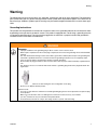
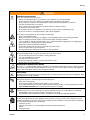
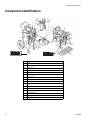
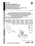
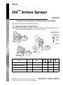
Repair
390
™
Airless Sprayer
310824D
- For portable spray applications of architectural paints and coatings 3300 psi (22.7MPa, 227bar) Maximum Working Pressure
IMPORTANT SAFETY INSTRUCTIONS!
Read all warnings and instructions. Save these instructions. Contact Graco Customer Service
or your local Graco distributor to obtain a manual in your language.
Related Manuals
310820
309639
309250
ti11608a
Stand
310876
ti11626a
Hi-Boy
ProStep
ti11583a
Model*
VAC
Country
262019, 253958
120
North America
240
Europe / Europe
multicord
254998, 262024, 256392
240
Asia / Australia
256481, 253961
110
UK
254968, 254969, 256391
*all models not available in all countries
Graco Inc., PO Box 1441, Minneapolis, MN 55440-1441
Copyright 2004, Graco Inc. is registered to I.S. EN ISO 9001
✔
✔
✔
✔
Manual Conventions
Contents
Manual Conventions . . . . . . . . . . . . . . . . . . . . . . . . 2
Warnings . . . . . . . . . . . . . . . . . . . . . . . . . . . . . . . . . 3
Component Identification . . . . . . . . . . . . . . . . . . . . 5
Installation . . . . . . . . . . . . . . . . . . . . . . . . . . . . . . . . 6
Pressure Relief Procedure . . . . . . . . . . . . . . . . . . . 7
General Repair Information . . . . . . . . . . . . . . . . . . 8
Troubleshooting . . . . . . . . . . . . . . . . . . . . . . . . . . . . 9
Displacement Pump Replacement . . . . . . . . . . . . 13
Drive Housing Replacement . . . . . . . . . . . . . . . . . 15
Spin Test . . . . . . . . . . . . . . . . . . . . . . . . . . . . . . . . . 16
Fan Replacement . . . . . . . . . . . . . . . . . . . . . . . . . . 17
Motor Brush Replacement . . . . . . . . . . . . . . . . . . 18
Control Board Replacement . . . . . . . . . . . . . . . . . 19
Fuse Replacement . . . . . . . . . . . . . . . . . . . . . . . . . 21
Pressure Control Assembly Replacement . . . . . . 22
Manifold Replacement . . . . . . . . . . . . . . . . . . . . . . 23
Power Cord Replacement . . . . . . . . . . . . . . . . . . . 24
Motor Replacement . . . . . . . . . . . . . . . . . . . . . . . . 25
Wiring Diagram . . . . . . . . . . . . . . . . . . . . . . . . . . . 26
Technical Data . . . . . . . . . . . . . . . . . . . . . . . . . . . . 27
Graco Standard Warranty . . . . . . . . . . . . . . . . . . . 29
Graco Information . . . . . . . . . . . . . . . . . . . . . . . . . 30
Manual Conventions
WARNING
Hazard Symbol
WARNING: a potentially hazardous situation which, if
not avoided, could result in death or serious injury.
Warnings in the instructions usually include a symbol
indicating the hazard. Read the general Warnings
section for additional safety information.
2
CAUTION
CAUTION: a potentially hazardous situation which, if
not avoided, may result in property damage or
destruction of equipment.
Note
Additional helpful information.
310824D
Warning
Warning
The following warnings are for the setup, use, grounding, maintenance and repair of this equipment. The exclamation
point symbol alerts you to a general warning and the hazard symbol refers to procedure-specific risks. Refer back to
these warnings. Additional, product-specific warnings may be found throughout the body of this manual where applicable.
Grounding Instructions
This product must be grounded. In the event of an electrical short circuit, grounding reduces the risk of electric shock
by providing an escape wire for the electric current. This product is equipped with a cord having a grounding wire with
an appropriate grounding plug. The plug must be plugged into an outlet that is properly installed and grounded in
accordance with all local codes and ordinances.
WARNING
GROUNDING
•
Improper installation of the grounding plug is able to result in a risk of electric shock.
•
When repair or replacement of the cord or plug is required, do not connect the grounding wire to either flat blade
terminal.
•
The wire with insulation having an outer surface that is green with or without yellow stripes is the grounding wire.
•
Check with a qualified electrician or serviceman when the grounding instructions are not completely understood, or when in doubt as to whether the product is properly grounded.
•
Do not modify the plug provided; if it does not fit the outlet, have the proper outlet installed by a qualified electrician.
•
This product is for use on a nominal 120V circuit and has a grounding plug similar to the plug illustrated in the
figure below.
•
•
Only connect the product to an outlet having the same configuration as the plug.
Do not use an adapter with this product.
Extension Cords:
•
Use only a 3-wire extension cord that has a 3-blade grounding plug and a 3-slot receptacle that accepts the plug
on the product.
•
Make sure your extension cord is not damaged. If an extension cord is necessary, use 12 AWG
(2.5 mm2) minimum to carry the current that the product draws.
•
An undersized cord results in a drop in line voltage and loss of power and overheating.
310824D
3
Warning
WARNING
FIRE AND EXPLOSION HAZARD
Flammable fumes, such as solvent and paint fumes, in work area can ignite or explode. To help prevent fire and
explosion:
•
Do not spray flammable or combustible materials near an open flame or sources of ignition such as cigarettes,
motors, and electrical equipment.
•
Paint or solvent flowing through the equipment is able to result in static electricity. Static electricity creates a risk
of fire or explosion in the presence of paint or solvent fumes. All parts of the spray system, including the pump,
hose assembly, spray gun, and objects in and around the spray area shall be properly grounded to protect
against static discharge and sparks. Use Graco conductive or grounded high-pressure airless paint sprayer
hoses.
•
Verify that all containers and collection systems are grounded to prevent static discharge.
•
Connect to a grounded outlet and use grounded extensions cords. Do not use a 3-to-2 adapter.
•
Do not use a paint or a solvent containing halogenated hydrocarbons.
•
Keep spray area well-ventilated. Keep a good supply of fresh air moving through the area. Keep pump assembly
in a well ventilated area. Do not spray pump assembly.
•
Do not smoke in the spray area.
•
Do not operate light switches, engines, or similar spark producing products in the spray area.
•
Keep area clean and free of paint or solvent containers, rags, and other flammable materials.
•
Know the contents of the paints and solvents being sprayed. Read all Material Safety Data Sheets (MSDS) and
container labels provided with the paints and solvents. Follow the paint and solvents manufacturer’s safety
instructions.
•
Fire extinguisher equipment shall be present and working.
•
Sprayer generates sparks. When flammable liquid is used in or near the sprayer or for flushing or cleaning, keep
sprayer at least 20 feet (6 m) away from explosive vapors.
SKIN INJECTION HAZARD
•
Do not aim the gun at, or spray any person or animal.
•
Keep hands and other body parts away from the discharge. For example, do not try to stop leaks with any part
of the body.
•
Always use the nozzle tip guard. Do not spray without nozzle tip guard in place.
•
Use Graco nozzle tips.
•
Use caution when cleaning and changing nozzle tips. in the case where the nozzle tip clogs while spraying, follow the Pressure Relief Procedure for turning off the unit and relieving the pressure before removing the nozzle tip to clean.
•
Do not leave the unit energized or under pressure while unattended. When the unit is not in use, turn off the unit
and follow the Pressure Relief Procedure for turning off the unit.
•
High-pressure spray is able to inject toxins into the body and cause serious bodily injury. In the event that injection occurs, get immediate surgical treatment.
•
Check hoses and parts for signs of damage. Replace any damaged hoses or parts.
•
This system is capable of producing 3300 psi. Use Graco replacement parts or accessories that are rated a
minimum of 3300 psi.
•
Always engage the trigger lock when not spraying. Verify the trigger lock is functioning properly.
•
Verify that all connections are secure before operating the unit.
•
Know how to stop the unit and bleed pressure quickly. Be thoroughly familiar with the controls.
4
310824D
Warning
WARNING
EQUIPMENT MISUSE HAZARD
Misuse can cause death or serious injury.
•
Always wear appropriate gloves, eye protection, and a respirator or mask when painting.
•
Do not operate or spray near children. Keep children away from equipment at all times.
•
Do not overreach or stand on an unstable support. Keep effective footing and balance at all times.
•
Stay alert and watch what you are doing.
•
Do not operate the unit when fatigued or under the influence of drugs or alcohol.
•
Do not kink or over-bend the hose.
•
Do not expose the hose to temperatures or to pressures in excess of those specified by Graco.
•
Do not use the hose as a strength member to pull or lift the equipment.
Misuse of the sprayer platform can cause death or serious injury.
•
Do not exceed platform rating.
•
Make sure sprayer is on firm, level, non-slippery, secure foundation before accessing sprayer platform.
•
Make sure platform has been properly secured to frame before standing on platform.
•
If you are unable to step up to sprayer platform, use a stable intermediate stepping device for stepping up to
sprayer platform or stepping down from sprayer platform.
•
Keep both feet squarely and firmly on platform.
•
Do not allow sprayer frame to come in contact with live electrical wires.
•
Do not over reach while on sprayer platform.
•
Do not position sprayer behind any doors when on sprayer platform.
ELECTRIC SHOCK HAZARD
Improper grounding, setup, or usage of the system can cause electric shock.
•
Turn off and disconnect power cord before servicing equipment.
•
Use only grounded electrical outlets.
•
Use only 3-wire extension cords.
•
Ensure ground prongs are intact on sprayer and extension cords.
•
Do not expose to rain. Store indoors.
PRESSURIZED ALUMINUM PARTS HAZARD
Do not use 1, 1, 1-trichloroethane, methylene chloride, other halogenated hydrocarbon solvents or fluids containing
such solvents in pressurized aluminum equipment. Such use can cause serious chemical reaction and equipment
rupture, and result in death, serious injury, and property damage.
BURN HAZARD
Equipment surfaces can become very hot during operation. To avoid severe burns, do not touch hot equipment. Wait
until equipment has cooled completely.
MOVING PARTS HAZARD
Moving parts can pinch or amputate fingers and other body parts.
•
Keep clear of moving parts.
•
Do not operate equipment with protective guards or covers removed.
•
Pressurized equipment can start without warning. Before checking, moving, or servicing equipment, follow the
Pressure Relief Procedure in this manual. Disconnect power or air supply.
TOXIC FLUID OR FUMES HAZARD
Toxic fluids or fumes can cause serious injury or death if splashed in the eyes or on skin, inhaled, or swallowed.
•
Read MSDS’s to know the specific hazards of the fluids you are using.
•
Store hazardous fluid in approved containers, and dispose of it according to applicable guidelines.
PERSONAL PROTECTIVE EQUIPMENT
You must wear appropriate protective equipment when operating, servicing, or when in the operating area of the
equipment to help protect you from serious injury, including eye injury, inhalation of toxic fumes, burns, and hearing
loss. This equipment includes but is not limited to:
•
Protective eye wear
•
Clothing and respirator as recommended by the fluid and solvent manufacturer
•
Gloves
•
Hearing protection
310824D
5
Component Identification
Component Identification
P
S
R
U
B
B
U
K
E
A
A
E
M
N
H
F
H
F
D
J
D
K
ti12008a
J
T
Item
6
T
V
English
A
Pressure Control
B
ON/OFF switch
D
Power Cord
E
Fluid Outlet
F
Prime Valve
H
Pump
J
Suction Hose
K
Drain Hose
M
Fluid Hose
N
Gun
P
Tip
R
Guard
S
Trigger Safety Lock
T
Model/Serial Tag
U
Filter
V
Platform
310824D
Installation
Installation
Grounding and Electric
Requirements
Do not use the sprayer if the electrical cord has a damaged ground contact. Only use an extension cord with
an undamaged ground contact.
WARNING
Your system must be grounded. Read warnings, page
3.
The sprayer cord includes: a grounding wire with an
appropriate grounding contact.
Recommended extension cords for use with this
sprayer:
• 110-120V: 3-wire, 12 AWG (2.5 mm2) minimum, 300
ft. (90 m) maximum length.
• 240V: 3-wire, 16 AWG (1.0 mm2) minimum, 300 ft
(90 m) maximum length.
Smaller gauge or longer extension cords may
reduce sprayer performance.
The sprayer requires:
110-120V Units: 100-130VAC, 50/60 Hz, 11A, 1 phase,
circuit with a grounding receptacle.
240V Units: 210-255 VAC, 50/60 Hz, 7.5A, 1 phase, circuit with a grounding receptacle.
Never use an outlet that is not grounded or an
adapter.
Spray gun: ground through connection to a properly
grounded fluid hose and pump.
Fluid supply container: follow local code.
Solvent and Oil-based fluids: follow local code. Use
only conductive metal pails placed on a grounded surface such as concrete. Do not place the pail on a nonconductive surface such as paper or cardboard, which
interrupts grounding continuity.
Grounding the metal pail: connect a ground wire to the
pail by clamping one end to pail and other end to ground
such as a water pipe.
To maintain grounding continuity when flushing or
relieving pressure: hold metal part of the spray gun
firmly to the side of a grounded metal pail, then trigger
the gun.
310824D
7
Pressure Relief Procedure
Pressure Relief Procedure
3. Turn prime valve down.
WARNING
Follow this Pressure Relief Procedure whenever you
are instructed to relieve pressure, stop spraying, check
or service equipment or install or clean spray tip. Read
Injection Hazard Warning, page 3.
ti5304a
1. Turn OFF power and turn pressure control to lowest
pressure setting.
2. Hold gun against side of grounded metal flushing
pail. Trigger gun to relieve pressure.
If you suspect the spray tip or hose is clogged or that
pressure has not been fully relieved after following the
steps above, VERY SLOWLY loosen tip guard retaining
nut or hose end coupling to relieve pressure gradually,
then loosen completely. Clear hose or tip obstruction.
4. Engage trigger safety lock on gun if unit is being
shut down or left unattended.
ti5310a
FLUSH
8
310824D
General Repair Information
General Repair Information
WARNING
Read Electric Shock Warning, page 3 and Burn
Hazard Warning, page 4.
WARNING
Flammable materials spilled on hot, bare, motor could
cause fire or explosion. To reduce risk of burns, fire or
explosion, do not operate sprayer with cover removed.
•
Keep all screws, nuts, washers, gaskets, and electrical fittings removed during repair procedures. These
parts usually are not provided with replacement kits.
•
Test repairs after problems are corrected.
•
If sprayer does not operate properly, review repair
procedure to verify you did it correctly. See Troubleshooting, page 10.
•
Overspray may build up in the air passages.
Remove any overspray and residue from air passages and openings in the enclosures whenever
you service sprayer.
•
Do not operate the sprayer without the motor shroud
in place. Replace if damaged. Motor shroud directs
cooling air around motor to prevent overheating and
insulate the control board from accidental electric
shock.
310824D
WARNING
To reduce risk of serious injury, including electric
shock:
• Do not touch moving or electric parts with fingers
or tools while testing repair.
• Unplug sprayer when power is not required for
testing.
• Install all covers, gaskets, screws and washers
before you operate sprayer.
•
CAUTION
Do not run sprayer dry for more than 30 seconds.
Doing so could damage pump packings.
•
Protect the internal drive parts of this sprayer from
water. Openings in the cover allow for air cooling of
the mechanical parts and electronics inside. If
water gets in these openings, the sprayer could
malfunction or be permanently damaged.
•
Prevent pump corrosion and damage from freezing.
Never leave water or water-base paint in sprayer
when its not in use in cold weather. Freezing fluids
can seriously damage sprayer. Store sprayer with
Pump Armor to protect sprayer during storage.
9
Troubleshooting
Troubleshooting
WARNING
Read Electric Shock Warning, page 3, Burn Hazard
Warning, page 4 and Pressure Relief Procedure,
page 8.
Problem
What To Check
What To Do
(If check is OK, go to next check)
(When check is not OK, refer to this column)
Motor Won’t Operate
Basic Fluid Pressure
Basic Mechanical
1. Pressure control knob setting.
Motor will not run if set at minimum (fully counter-clockwise).
Slowly increase pressure setting to see if motor
starts.
2. Spray tip or fluid filter may be
clogged.
Relieve pressure, page 8. Then clear clog or
clean gun filter. Refer to gun instruction manual,
309639.
1. Pump frozen or hardened paint
Thaw sprayer if water or water-based paint has
frozen in sprayer. Place sprayer in warm area to
thaw. Do not start sprayer until thawed completely. If paint hardened (dried) in sprayer,
replace pump packings. See page 14, Displacement Pump Replacement.
2. Displacement pump connecting Push pin into place and secure with spring
rod pin. Pin must be completely retainer. See page 14, Displacement Pump
pushed into connecting rod and Replacement.
retaining spring must be firmly in
groove or pump pin.
3. Motor. Remove drive housing
assembly. See page 16, Drive
Housing Replacement. Try to
rotate fan by hand.
10
Replace motor if fan won’t turn. See page 27,
Motor Replacement.
310824D
Troubleshooting
Problem
Basic Electrical
See wiring diagram, page
28
What To Check
What To Do
(If check is OK, go to next check)
(When check is not OK, refer to this column)
1. Electric supply. Meter must read Reset building circuit breaker, replace building
fuses. Try another outlet.
100-130 VAC for 110-120 VAC
models and 210-255 VAC for 240
VAC models.
2. Extension cord. Check extension Replace extension cord.
cord continuity with volt meter.
3. Sprayer power supply cord.
Replace power supply cord. See page 26,
Inspect for damage such as bro- Power Cord Replacement.
ken insulation or wires.
4. Fuse. Check replaceable fuse on Replace fuse after completing motor inspection.
control board (next to ON/OFF
See page 22, Fuse Replacement.
switch).
Replace loose terminals; crimp to leads. Be
5. Motor leads are securely fastened and properly connected to sure terminals are firmly connected.
control board.
Clean circuit board terminals. Securely reconnect leads.
Replace motor. See page 27, Motor Replace6. Motor thermal switch. Yellow
motor leads must have continuity ment.
through thermal switch.
7. Brush cap missing or loose brush Install brush cap or replace brushes if leads are
lead connections.
damaged. See page 19, Motor Brush
Replacement.
8. Brush length which must be 1/4
in. (6mm) minimum.
Replace brushes. See page 19, Motor Brush
Replacement.
NOTE: Brushes do not wear at
the same rate on both sides of
motor. Check both brushes.
9. Motor armature commutator for Remove motor and have motor shop resurface
burn spots, gouges and extreme commutator if possible. See page 27, Motor
roughness.
Replacement.
310824D
10. Motor armature for shorts using
armature tester (growler) or perform spin test, page 17.
Replace motor. See page 27, Motor Replacement.
11. Pressure control not plugged in
to control board.
Insert pressure control connector into control
board.
11
Troubleshooting
Problem
Low Output
What To Check
What To Do
(If check is OK, go to next check)
(When check is not OK, refer to this column)
1. Worn spray tip.
Relieve pressure, page 8. Replace tip. Refer to
gun instruction manual, 309639.
2. Verify pump does not continue to Service pump. See page 14, Displacement
stroke when gun trigger is
Pump Replacement.
released.
3. Prime valve leaking.
Relieve pressure, page 8. Then repair prime
valve. See page 24, Manifold Replacement.
4. Suction hose connections.
Tighten any loose connections. Check o-rings
on suction hose swivel.
Reset building circuit breaker; replace building
5. Electric supply with volt meter.
Meter must read 100-130 VAC for fuse. Repair electrical outlet or try another
outlet.
110-120 VAC models and
210-255 for 240 VAC models.
Low voltages reduce sprayer performance.
6. Extension cord size and length.
7. Replace with a correct, grounded extension
cord. See page 7, Grounding and Electric
Requirements.
8. Leads from motor to circuit board
for damaged or loose wire connectors. Inspect wiring insulation
and terminals for signs of overheating.
Be sure male terminal pins are centered and
firmly connected to female terminals. Replace
any loose terminals or damaged wiring.
Securely reconnect terminals.
9. Worn motor brushes which must Replace brushes. See page 19. Motor Brush
be 1/4 in. (6 mm) minimum.
Replacement.
10. Motor brushes binding in brush
holders.
11. Low stall pressure. Turn pressure
control knob fully clockwise.
12. Motor armature for shorts by
using an armature tester
(growler) or perform spin test,
page 17.
12
Clean brush holders. Remove carbon dust by
using compressed air to blow out brush dust.
Replace pressure control assembly. See page
23, Pressure Control Assembly Replacement.
Replace motor. See page 27, Motor
Replacement.
310824D
Troubleshooting
Problem
Motor runs and pump
strokes
Motor runs but pump does
not stroke
Motor is hot and runs
intermittently
What To Check
What To Do
(If check is OK, go to next check)
(When check is not OK, refer to this column)
1. Prime Valve Open.
Close prime valve.
2. Paint supply.
Refill and reprime pump.
3. Intake strainer clogged.
Remove and clean, then reinstall.
4. Suction hose leaking air.
Tighten nut. Check o-rings on swivel.
5. Intake valve ball and piston ball
are seating properly.
See Pump Manual 309250. Strain paint before
using to remove particles that could clog pump.
6. Leaking around throat packing
nut which may indicate worn or
damaged packings.
See Pump Manual 309250.
7. Pump rod damaged.
See Pump Manual 309250.
1. Displacement pump pin damaged or missing.
Replace pump pin if missing. Be sure retaining
spring is fully in groove all around connecting
rod. See page 14, Displacement Pump
Replacement.
2. Connecting rod assembly for
damage.
Replace connecting rod assembly. See page
14, Displacement Pump Replacement.
3. Gears or drive housing.
Inspect drive housing assembly and gears for
damage and replace if necessary. See page 16,
Drive Housing Replacement.
1. Be sure ambient temperature
where sprayer is located is not
more than 115°F (46°C) and
sprayer is not located in direct
sun.
Move sprayer to shaded, cooler area if possible.
2. Motor has burned windings indicated by removing positive (red)
brush and seeing burned adjacent commutator bars.
Replace motor. See page 27, Motor
Replacement.
3. Tightness of pump packing nut. Loosen packing nut. Check for leaking around
Overtightening tightens packings throat. Replace pump packings if necessary.
on rod, restricts pump action and See pump manual 309250.
damages packings.
310824D
13
Displacement Pump Replacement
Displacement Pump Replacement
See manual 309250 for pump repair instructions.
Removal
4. Cycle pump until pin (32) is in position to be
removed.
5. Disconnect power cord from outlet.
6. Using a flat screwdriver, push retaining spring (C)
up. Push out pump pin (32).
WARNING
Read Injection Hazard Warning, page 3, Moving
Parts Hazard Warning, page 4 and Pressure Relief
Procedure, page 8.
1. Relieve pressure, page 8.
C
2. Loosen two screws (30) and rotate cover (44).
32
ti6104a
44
30
3. Loosen nut (A) and remove hose set (35). Loosen
nut (B) and remove the high pressure hose (14).
ti6106a
7. Using a hammer, loosen pump jam nut (11).
Unscrew and remove pump (9).
ti6107a
11
9
14
11
B
A
35
14
ti6105a
310824D
Displacement Pump Replacement
Installation
5. Screw in pump until threads are flush with top of
drive housing opening.
WARNING
If pump pin works loose, parts could break off due to
force of pumping action. Parts could project through
air and result in serious injury or property damage.
CAUTION
If the pump jam nut loosens during operation, the
threads of the drive housing will be damaged.
6. Align pump outlet (E) to back.
1. Extend pump piston rod full. Apply grease to top of
pump rod at (D) or inside connecting rod (7). Install
jam nut (11) on pump threads.
%
$
7. Screw jam nut (11) up onto pump until nut stops.
Tighten jam nut by hand, then tap 1/8 to 1/4 turn
with a 20 oz (maximum) hammer to approximately
75 ft-lb (102 N•m).
TIA
2. Install pump rod (D) into connecting rod (7).
8. Install suction tube (35) and high pressure hose
(14). Tighten nuts (A) and (B).
.
3. Install pump pin (32). Verify retainer spring (C) is in
groove over pump pin.
14
#
B
A
35
ti6105a
9. Fill packing nut with Graco TSL until fluid flows onto
top of seal.
TIA
4. Push pump (9) up until pump threads engage.
30
44
ti5735a
10. Rotate cover (44). Tighten screws (30).
310824D
15
Drive Housing Replacement
Drive Housing Replacement
Installation
WARNING
1. Apply a liberal coat of grease to gears and needle
bearing surfaces. Install thrust bearing (4) and
gears (2) and (3) in front endbell housing.
Read Injection Hazard Warning, page 3 and page 8.
Needle
bearing
surfaces
Removal
1. Relieve pressure, page 8.
3
2. Remove pump (9). Displacement Pump Replacement, page 14. Disconnect power cord from outlet.
4
3
4
2
5
7
ti6121a
6
ti5641a
32
30
2
6
2. Push drive housing into front endbell housing. Insert
gear crank (3) through hole in connecting rod (7).
3
3. Remove two screws (30) and cover (32).
4. Remove four screws (6).
7
5. Pull drive housing (5) out of motor front endbell.
6. Remove gear cluster (2) and (3) and thrust bearing
(4) from drive housing.
ti6124a
CAUTION
Do not drop gear cluster (3) and (2) when removing
drive housing (5). Gear cluster may stay engaged in
motor front endbell or drive housing.
3. Install four screws (6).
4. Install cover (32) with two screws (30).
5. Install pump (9). Displacement Pump Replacement, page 14.
16
310824D
Spin Test
Spin Test
See Wiring Diagram, page 28.
WARNING
2. If uneven or no resistance, check for missing brush
caps, broken brush springs, brush leads, and worn
brushes. Repair as needed, page 19.
3. If still uneven or no resistance, replace motor, page
27.
Read Electric Shock Warning, page 3 and Pressure
Relief Procedure, page 8.
30
To check armature, motor winding and brush electrical
continuity:
1. Relieve pressure, page 8. Disconnect power cord
from outlet.
29
2. Remove two screws (30) and shroud (29).
3. Remove drive housing (5), page 16.
4. Disconnect motor connector (F).
Armature Short Circuit Test
ti5638a
F
Quickly turn motor fan by hand. If motor coasts two or
three revolutions before complete stop, there are no
electrical shorts. If motor does not spin freely, armature
is shorted. Replace motor, page 27.
4. Reattach motor connector (F).
Armature, Brushes, and Motor Wiring Open
Circuit Test (Continuity)
1. Connect red and black motor leads with test lead.
Turn motor fan by hand at about two revolutions per
second.
310824D
5. Replace drive housing, page 16.
6. Replace shroud (29) and two screws (30).
17
Fan Replacement
Fan Replacement
Removal
3. Remove spring clip (101) on back of motor.
WARNING
4. Pull off fan (100).
Read Electric Shock Warning, page 3 and Pressure
Relief Procedure, page 8.
1. Relieve pressure, page 8. Disconnect power cord
from outlet.
2. Remove two screws (30) and shroud (29).
Installation
1. Slide new fan (100) in place on back of motor. Be
sure blades of fan face motor as shown.
2. Install spring clip (101).
3. Replace shroud (29) and two screws (30).
100
30
101
29
ti5769a
18
310824D
Motor Brush Replacement
Motor Brush Replacement
See Wiring Diagram, page 28.
Removal
Replace brushes worn to less than 1/4 in. (6mm).
Brushes wear differently on each side of motor, check
both sides.
WARNING
2. Push each cap (A) into place over brush. Orient
each cap with the 2 projections on either side of the
brush lead. You will hear a “snap” when cap is
securely in place.
3. Using a wire stripper, strip off wire insulation approximately 1/4 inch (6 mm) from the end of each yellow
wire (C) to the motor.
4. Insert stripped end into end of a butt splice (E) on
new brush assembly.
Read Electric Shock Warning, page 3 and Pressure
Relief Procedure, page 8.
5. Use a crimping tool to squeeze the ends of the butt
splice (E) tightly around each wire. Pull gently on
each wire to be sure it will not pull out of the butt
splice.
1. Relieve pressure, page 8. Disconnect power cord
from outlet.
6. Using new tie wrap (F) from kit, wrap tie around
motor and wires only. Trim off excess. Be sure pressure hose and wire leads are not caught in tie wrap.
2. Remove two screws (30) and shroud (29).
3. Disconnect motor connector (D) from control board
(33).
7. Reconnect motor connector (D) to control board
(33).
4. Cut tie wrap (F).
30
5. Locate two yellow wires (C) (thermal leads). Cut
each yellow wire at the center.
D
6. Using a flat screwdriver, pry off (two) brush caps
(A). Remove brushes (B) from motor.
7. Discard old brush harness.
8. While rotating fan by hand, using compressed air,
blow air into positive (top) brush holder to remove
brush dust.
To contain the dust, turn on your shop vac. Place
the end of the hose over the negative (lower) brush
holder while blowing compressed air into the positive (top) brush holder.
Installation
29
A
E
ti5637a
33
A
+
Red
C
D
B
-
F
Black
ti5637a
\
Use all new parts included in your brush kit. Do not
reuse old parts if new replacement parts are provided.
1. With wires facing toward front of motor, install new
brushes (B) in motor. Be sure to install the positive
(red) brush lead in the top of the motor (as shown)
and the negative (black) brush lead in the side of the
motor.
310824D
8. Replace shroud (29) and two screws (30).
19
Control Board Replacement
Control Board Replacement
6. Pull control board out slightly and then slide it back
and off of frame.
See Wiring Diagram, page 28.
WARNING
Make sure power cord is free and NOT wrapped
around cord wrap.
Read Electric Shock Warning, page 3 and Pressure
Relief Procedure, page 8.
7. Remove grommet and wires from strain relief.
Removal
1. Relieve pressure, page 8. Disconnect power cord
from outlet.
A
B
B
2. Remove two screws (30) and shroud (29).
3. Disconnect pressure switch connector (A) from control board (33).
A
4. Disconnect motor connector (B) from control board
(33).
5. Remove 3 screws (30) securing control board to
housing (2 are located on the front and one on the
back next to the power cord).
33
33
240V
120V
.
Ground wire will remain attached to sprayer with
grounding screw.
8. Remove 2 power cord connectors from control
board.
33
30
30
ti6119a
20
310824D
Control Board Replacement
Installation
1. Position grommet and power cord wires through
strain relief in control board (33).
ti6122a
ti6125a
33
3. Carefully slide control board back into place on the
side of the motor frame.
2. Reconnect the power cord connectors to the correct
terminals indicated on the control board (120V,
black and white, 240V, blue and brown) on control
board (33).
Be sure power cord is routed between the blue high
pressure hose to the manifold and the sprayer
frame.
4. Replace 3 screws (30). Torque to 30-35 in-lbs
(3.4-3.9 N.m)
5. Reattach motor connector (B) and pressure control
assembly connector (A).
6. Install shroud (29) and two screws (30).
B
A
33
120V
B
A
33
30
J
D
E
30
F
G
ti5639a
H
310824D
21
Fuse Replacement
Fuse Replacement
Removal
Installation
1. Relieve pressure, page 8. Disconnect power cord
from outlet.
1. Replace fuse on control board with spare fuse.
2. Install shroud (29) and two screws (30).
2. Remove two screws (30) and shroud (29).
3. Remove fuse from control board.
4. Remove spare fuse from motor.
Replaceable Fuse
Spare Fuse
(included n
110V and 120
models only)
ti9134b
22
310824D
Pressure Control Assembly Replacement
Pressure Control Assembly Replacement
See Wiring Diagram, page 28.
30
WARNING
29
Read Electric Shock Warning, page 3 and Pressure
Relief Procedure, page 8.
Removal
1. Relieve pressure, page 8. Disconnect power cord
from outlet.
2. Remove two screws (30) and shroud (29).
ti5766a
3. Disconnect pressure switch connector (A) from control board (33).
4. Remove tape (22) holding wires to manifold.
5. Pull wires back through hole (K) in housing.
If you plan to reuse the pressure control assembly,
be very careful not to damage or tangle the wires
while unscrewing the assembly.
8. Remove pressure control assembly.
Installation
Inspect pressure control assembly before installation to verify the o-ring is installed and in place.
1. Align grommet collar (17) on fluid manifold so opening faces toward motor.
2. Apply loctite to pressure control assembly threads
(16)
3. Screw pressure control assembly (16) into manifold
and torque to 150 in-lbs (17.0 N.m)
A
22
21
K
TIC
6. Turn the pressure control knob (16) counter clockwise as far as you can to access the flats on either
side of the pressure control assembly.
7. Using a 1 in. (26 mm) wrench loosen and unscrew
pressure control assembly.
Be careful when tightening pressure control knob
that wires do not get pinched between the pressure
control assembly and fluid manifold.
4. Wrap wires around knob and feed through slot in
grommet (21).
5. Insert grommet (21) in hole (K) in housing. Secure
wires to manifold housing with tape (22).
6. Reconnect pressure switch connector (A) to control
board (33).
7. Install shroud (29) and two screws (30).
310824D
23
Manifold Replacement
Manifold Replacement
See Wiring Diagram, page 28.
WARNING
7. Reconnect fluid hose at pump outlet.
8. Replace barbed fitting (20) and drain line (40). See
Drain Line Replacement, page 25.
9. Install shroud (29) and two screws (30).
Read Electric Shock Warning, page 3 and Pressure
Relief Procedure, page 8.
Removal
A
1. Relieve pressure, page 8. Disconnect power cord
from outlet.
18
33
A
2. Remove drain line (40) and barbed fitting (20) from
manifold. See Drain Line Replacement, page 25.
3. Remove two screws (30) and shroud (29).
17
4. Disconnect fluid hose at pump outlet.
5. Disconnect pressure switch connector (A) from control board (33).
15
13
Ref 14
C
20
6. Remove tape (22) holding wires to manifold.
7. Pull wires back through hole (K) in housing.
23 6
24
25
26
8. If required, remove pressure switch from manifold.
See Pressure Control Assembly Replacement,
page 23.
B
40
ti5771a
A
9. Remove two screws (6) to disconnect Manifold from
housing.
33
Installation
A
18
1. Position manifold on sprayer frame.
17
2. Replace screws (6) and torque to 150 in-lbs (17
N.m).
3. If removed, install pressure control assembly. See
Pressure Control Assembly Replacement, page
23.
ProStep
13
Ref 14
6
4. Feed pressure switch wires through hole in housing
(K).
5. Insert grommet (21) in hole (K) in housing. Secure
wires to manifold housing with tape (22).
20
23
24
40
25
26
ti12077a
6. Reconnect pressure switch connector (A) to control
board (33).
24
310824D
Drain Line Replacement
Drain Line Replacement
This procedure should be used whenever you replace
the manifold and reinstall an existing drain line or install
a new drain line using the Drain Line Kit.
Removal
To remove the drain line (40) from the manifold:
1. Cut drain line (40) from barbed fitting (20).
2. Unscrew barbed fitting (20) from manifold.
If you are only replacing the manifold and will be
reusing the existing barbed fitting (20) and drain
line (40), you will need to use a sharp knife to cut
the remaining drain line material off the end of the
barbed fitting (20).
Installation
1. Screw barbed fitting (20) into manifold.
2. Push drain line (40) onto barbed fitting (20).
To make the drain line more pliable and easier to
install over barbed fitting, heat end of drain line (40)
with a hair dryer or by placing end in hot water a
few seconds.
310824D
25
Power Cord Replacement
Power Cord Replacement
Installation
See Wiring Diagram, page 28.
1. Follow Control Board Replacement installation
instructions, steps 1-4, page 20.
WARNING
Read Electric Shock Warning, page 3 and Pressure
Relief Procedure, page 8.
Removal
2. Reconnect, green ground wire (G) to green grounding screw (31) on frame. Be sure terminal on ground
faces UP or wires could get caught in shroud.
3. Reattach motor connector (B) and pressure control
switch connect (A).
4. Install shroud (29) and two screws (30).
1. Follow Control Board Replacement removal
instructions, steps 1-8, page 20.
2. Disconnect green ground wire (G) from sprayer by
loosening grounding screw (31).
33
33
240V
120V
G
31
26
310824D
Motor Replacement
Motor Replacement
5. Disconnect all leads from board (33) and remove
control board. Control Board Replacement, page
20.
See Wiring Diagram, page 28.
WARNING
6. Remove ground wire (G) from motor endbell.
Read Electric Shock Warning, page 3 and Pressure
Relief Procedure, page 8.
7. Remove four screws (6) and motor (1) from frame
(45).
Installation
CAUTION
Do not drop gear cluster (3) and (2) when removing
drive housing (5). Gear cluster may stay engaged in
motor frontend bell or drive housing.
1. Install new motor (1) on frame (45) with four screws
(6).
2. Install manifold (15) with two screws (6). Manifold
Replacement, page 24
Removal
1. Relieve pressure, page 8. Disconnect power cord
from outlet.
2. Remove pump (9). Displacement Pump Replacement, page 14.
3. Remove drive housing, Drive Housing Replacement, page 16.
4. Remove Pressure (Fluid) Manifold, Manifold
Replacement, page 24.
3. Install control board (33) with three screws (30).
Connect all leads to board. See Control Board
Replacement, page 20 and Wiring Diagram, page
28.
4. Connect ground wire (G) to motor with green ground
screw (31).
5. Install Drive Housing. Drive Housing Replacement, page 16.
6. Install pump (9). Displacement Pump Replacement, page 14.
7. Install shroud (29) with two screws (30).
31
34
1
33
30
3
1
30
2
15
1
6
6
45
ti5642a
1
310824D
Liberally apply grease
27
Wiring Diagram
Wiring Diagram
120V Model
from Motor
Red (+)
2 x Yellow
Black (-)
Replaceable Fuse
Pressure
Control
Assembly
ON/OFF
Switch
ti5643a
Black
Power
Plug
Capacitor
White
Green
240V Model
Capacitor
Pressure Control
Assembly
from Motor
Red (+)
2 x Yellow
Black (-)
Replaceable Fuse
ON/OFF
Switch
ti5857a
Blue
Brown
Power
Plug
Green
28
310824D
Technical Data
Technical Data
Power requirements . . . . . . . . . . . . . . . . . . . . . . . . . . . . . 100/120V AC, 50/60 hz, 11A, 1 phase
230V AC, 50/60 hz, 7.5A, 1 phase
Generator required . . . . . . . . . . . . . . . . . . . . . . . . . . . . . . 3000 w minimum
Maximum working pressure . . . . . . . . . . . . . . . . . . . . . . . 3300 psi (22.7 MPa, 227 bar)
Cycles per gallon (liter) . . . . . . . . . . . . . . . . . . . . . . . . . . . 680 (180)
Maximum delivery gpm (lpm) . . . . . . . . . . . . . . . . . . . . . . 0.43 (1.6)
Maximum tip size . . . . . . . . . . . . . . . . . . . . . . . . . . . . . . . 0.020
Fluid outlet npsm . . . . . . . . . . . . . . . . . . . . . . . . . . . . . . . 1/4 in.
Dimensions (Stand):
Length . . . . . . . . . . . . . . . . . . . . . . . . . . . . . . . . . . . . 15.75 in. (40.0 cm)
Width . . . . . . . . . . . . . . . . . . . . . . . . . . . . . . . . . . . . . 14.0 in. (36.0 cm)
Height . . . . . . . . . . . . . . . . . . . . . . . . . . . . . . . . . . . . . 17 in. (43.0 cm)
Weight. . . . . . . . . . . . . . . . . . . . . . . . . . . . . . . . . . . . . . . . 30 lb (13.6 kg)
Dimensions (Hi-Boy):
Length . . . . . . . . . . . . . . . . . . . . . . . . . . . . . . . . . . . . 22.0 in. (55.9 cm)
Width . . . . . . . . . . . . . . . . . . . . . . . . . . . . . . . . . . . . . 20.5 in. (52.1 cm)
Height . . . . . . . . . . . . . . . . . . . . . . . . . . . . . . . . . . . . . 38.8 in. (98.6 cm)
Weight. . . . . . . . . . . . . . . . . . . . . . . . . . . . . . . . . . . . . . . . 58.0 lb (25.9 kg)
Dimensions (ProStep):
Length . . . . . . . . . . . . . . . . . . . . . . . . . . . . . . . . . . . . 20.0 in. (50.8 cm)
Width . . . . . . . . . . . . . . . . . . . . . . . . . . . . . . . . . . . . . 15.5 in. (39.4 cm)
Height . . . . . . . . . . . . . . . . . . . . . . . . . . . . . . . . . . . . . 19.25 in. (48.9 cm)
Weight. . . . . . . . . . . . . . . . . . . . . . . . . . . . . . . . . . . . . . . . 40.0 lb (18.1 kg)
Wetted parts . . . . . . . . . . . . . . . . . . . . . . . . . . . . . . . . . . . zinc and nickel-plated carbon steel, nylon, stainless steel,
PTFE, Delrin®, leather, UHMWPE, aluminum, tungsten
carbide
Noise level*
Sound power (IS0 3744)
100dBa*
Sound pressure (ISO 3744)
90 dBa*
Delrin® is a registered trademark of the DuPont Company.
*Measured 3 feet (1 meter) from equipment.
310824D
29
Graco Standard Warranty
Graco warrants all equipment referenced in this document which is manufactured by Graco and bearing its name to be free from defects in material
and workmanship on the date of sale to the original purchaser for use. With the exception of any special, extended, or limited warranty published by
Graco, Graco will, for a period of twelve months from the date of sale, repair or replace any part of the equipment determined by Graco to be
defective. This warranty applies only when the equipment is installed, operated and maintained in accordance with Graco’s written
recommendations.
This warranty does not cover, and Graco shall not be liable for general wear and tear, or any malfunction, damage or wear caused by faulty
installation, misapplication, abrasion, corrosion, inadequate or improper maintenance, negligence, accident, tampering, or substitution of
non-Graco component parts. Nor shall Graco be liable for malfunction, damage or wear caused by the incompatibility of Graco equipment with
structures, accessories, equipment or materials not supplied by Graco, or the improper design, manufacture, installation, operation or maintenance
of structures, accessories, equipment or materials not supplied by Graco.
This warranty is conditioned upon the prepaid return of the equipment claimed to be defective to an authorized Graco distributor for verification of
the claimed defect. If the claimed defect is verified, Graco will repair or replace free of charge any defective parts. The equipment will be returned
to the original purchaser transportation prepaid. If inspection of the equipment does not disclose any defect in material or workmanship, repairs will
be made at a reasonable charge, which charges may include the costs of parts, labor, and transportation.
THIS WARRANTY IS EXCLUSIVE, AND IS IN LIEU OF ANY OTHER WARRANTIES, EXPRESS OR IMPLIED, INCLUDING BUT NOT LIMITED
TO WARRANTY OF MERCHANTABILITY OR WARRANTY OF FITNESS FOR A PARTICULAR PURPOSE.
Graco’s sole obligation and buyer’s sole remedy for any breach of warranty shall be as set forth above. The buyer agrees that no other remedy
(including, but not limited to, incidental or consequential damages for lost profits, lost sales, injury to person or property, or any other incidental or
consequential loss) shall be available. Any action for breach of warranty must be brought within two (2) years of the date of sale.
GRACO MAKES NO WARRANTY, AND DISCLAIMS ALL IMPLIED WARRANTIES OF MERCHANTABILITY AND FITNESS FOR A
PARTICULAR PURPOSE, IN CONNECTION WITH ACCESSORIES, EQUIPMENT, MATERIALS OR COMPONENTS SOLD BUT NOT
MANUFACTURED BY GRACO. These items sold, but not manufactured by Graco (such as electric motors, switches, hose, etc.), are subject to
the warranty, if any, of their manufacturer. Graco will provide purchaser with reasonable assistance in making any claim for breach of these
warranties.
In no event will Graco be liable for indirect, incidental, special or consequential damages resulting from Graco supplying equipment hereunder, or
the furnishing, performance, or use of any products or other goods sold hereto, whether due to a breach of contract, breach of warranty, the
negligence of Graco, or otherwise.
FOR GRACO CANADA CUSTOMERS
The Parties acknowledge that they have required that the present document, as well as all documents, notices and legal proceedings entered into,
given or instituted pursuant hereto or relating directly or indirectly hereto, be drawn up in English. Les parties reconnaissent avoir convenu que la
rédaction du présente document sera en Anglais, ainsi que tous documents, avis et procédures judiciaires exécutés, donnés ou intentés, à la suite
de ou en rapport, directement ou indirectement, avec les procédures concernées.
All written and visual data contained in this document reflects the latest product information available at the time of publication.
Graco reserves the right to make changes at any time without notice.
Graco Headquarters: Minneapolis
International Offices: Belgium, China, Japan, Korea
GRACO INC. P.O. BOX 1441 MINNEAPOLIS, MN 55440-1441
www.graco.com
Printed in USA 310824D
4/2008