1
INSTRUCTIONS-PARTS LIST
‘3
0
ORAICO
This manual contains IMPORTANT
WARNINGS and INSTRUCTIONS
READ AND RETAIN FOR REFERENCE
308-518
Rev
A
Supersedes 801-888
HYDRA-CLEAN @826,1235
Pressure Washers
HYDRA-CLEAN 826
Model 800-093, Series B
800 psi (55 bar) OPERATING PRESSURE
1100 psi (76 bar) MAXIMUM WORKING PRESSURE
HYDRA-CLEAN 1235
Model 800-268, Series A
7200 psi (83 bar) OPERATING PRESSURE
1500 psi (103 bar) MAX/MUM WORKING PRESSURE
GRACO INC. P.O. Box 1441 MINNEAPOLIS,
@COPYRIGHT 1990, GRACO INC.
MN 55440-1441
WARNING
HIGH PRESSURE SPRAY CAN CAUSE SERIOUS INJURY.
FOR PROFESSIONAL
USE ONLY OBSERVE ALL WARNINGS.
Read and understand
FLUID INJECTION
all instruction
manuals
before operating
equipment.
HAZARD
General Safety
Pressure Relief Procedure
This pressure washer generates very high fluid
pressure. Spray from the gun, leaks or ruptured
components can inject fluid through your skin and into
your body and cause extremely serious bodily injury
including the need for amputation. Also, fluid injected or
splashed into the eyes or on the skin can cause serious
damage.
To reduce the risk of serious bodily injury, including fluid
injection and splashing in the eyes, or on the skin,
always follow this procedure whenever you stop
spraying for more than 10 minutes, when shutting down,
and before checking or repairing any part of the system.
1.
Engage the trigger safety latch.
NEVER point the spray gun or wand at anyone or at any
part of the body. NEVER put hand or fingers over the
spray tip.
2.
Turn the sprayer off.
3.
Disconnect the electrical supply.
ALWAYS follow the Pressure Relief Procedure, before
cleaning or servicing any part of the sprayer.
4.
Shut off the water supply.
5.
Disengage the trigger safety latch and trigger the
gun to relieve pressure, and then engage the trigger
safety latch again.
6.
Before long-term (overnight) storage, disconnect
the water supply and disconnect the electricity.
NEVER try to stop or deflect leaks with your hand or
body.
Be sure equipment safety
properly before each use.
devices
are operating
Spray Gun Safety Devices
Medical Treatment
If any fluid
appears
to penetrate
your skin,
get
EMERGENCY MEDICALTREATMENTATONCE. DO
NOT TREAT AS A SIMPLE CUT. Tell the doctor exactly
what fluid was injected.
NOTE TO PHYSICIAN: Injection in the skin is a
traumatic injury It is important to treat the injury
surgically as soon as possible. Do not delay
treatment to research toxicity. Toxicity is a
concern with some exotic coatings injected
directly into the bloodstream. Consultation with a
surgeon or reconstructive hand surgeon
may be advisable.
plastic
GROUNDING
308-518
SAFETY
moment,
or “safe”
properly
triggering
LATCH: Whenever you stop spraying for a
always set the gun safety latch in the engaged
position, making the gun inoperative. Failure to
set the safety latch can result in accidental
of the gun.
SPRAY TIP SAFETY: Use extreme caution when
cleaning or changing spray tips. If a spray tip clogs
while spraying,
engage
the gun safety latch
immediately. ALWAYS follow the Pressure Relief
Procedure and then remove the spray tip to clean it.
INSTRUCTIONS
This product must be grounded. If it should malfunction
or break down, grounding provides a path of least
resistance for electric current to reduce the risk of
electric shock. This equipment is equipped with a cord
having an equipment-grounding
conductor and a
grounding plug. The plug must be plugged into an
appropriate
outlet that is properly installed and
grounded in accordance with all local codes and
ordinances.
2
Be sure all gun safety devices are operating properly
before each use. Do not remove or modify any part of
the gun; this can cause a malfunction and result in
serious bodily injury.
DANGER
Improper connection of the equipment- grounding
conductor can result in the risk of electrocution.
Check with a qualified electrician or service
person if you are in doubt as to whether the outlet
is properly grounded. Do not modify the plug
provided with the product - if it will not fit the outlet,
have a proper outlet installed by a qualified
electrician.
GROUND
FAULT CIRCUIT
INTERRUPTER
The 826 pressure washer is provided
with a
ground-fault
circuit-interrupter
(GFCI) built into the
power supply cord. This device provides additional
protection from the risk of electric shock. Should
replacement of the cord become necessary, use only
identical
replacement
parts that include
GFCI
protection.
GROUND
FAULT CIRCUIT
INTERRUPTER
To comply with the National Electrical Code (NFPA 70)
and to provide additional protection from the risk of
electric shock, connect the 1235 pressure washer to a
EXTENSION
PROTECTION
(826)
CAUTION
DO NOT use the switch on the GFCI cord to start
the unit. This may cause premature failure of the
GFCI. ALWAYS turn the machine off at the switch
before resetting the GFCI.
PROTECTION
(1235)
receptacle
that is protected
circuit-interrupter (GFCI).
by
a
ground-fault
CORDS
Use only 3-wire extension cords that have 3-prong
grounding-type plugs and 3-pole cord connectors that
accept the plug from the product. Use only extension
cords that are intended for outdoor use. These
extension cords are identified by a marking “Acceptable
for use with outdoor appliances; store indoors while not
in use.” Use only extension cords having an electrical
rating not less than the rating of the product. Do not use
damaged extension cords. Examine extension cord
before using and replace if damaged. Do not abuse
extension cord and do not yank or pull on any cord to
EQUIPMENT
disconnect. Keep cord away from heat and sharp
edges. Always disconnect the extension cord from the
receptacle before disconnecting the product from the
extension cord.
To reduce the risk of electrocution,
keep all
connections dry and off the ground. Do not touch
/,,,,,,,,,.,^‘“lNG
_?
MISUSE HAZARD
General Safety
System Pressure
Any misuse of the pressure washer or accessories,
such as overpressurizing,
modifying parts, using
incompatible chemicals and fluids, or using worn or
damaged parts, can cause them to rupture and result in
fluid injection, splashing in the eyes or on the skin, or
other serious bodily injury, fire, explosion or property
damage.
This sprayer can develop high operating pressure. Be
sure that all spray equipment and accessories are rated
to withstand the maximum working pressure of this
sprayer. DO NOT exceed the maximum working
pressure of any component or accessory used in the
system.
NEVER alter or modify any part of this equipment; doing
so could cause it to malfunction.
chemicals used in the chemical
BE SURE that
injector are compatible with the wetted parts of the
hose, gun, wand and tip, as given in the Technical Data
(page 22). Always read the chemical manufacturer’s
literature before using any chemical in this pressure
washer.
CHECK all spray equipment regularly and repair or
replace worn or damaged pans immediately.
ALWAYS wear protective eyewear and appropriate
clothing. If using a chemical injector, read and follow
manufacturer’s
literature
for
the
chemical
recommendations on additional protective equipment,
such as a respirator.
Chemical Compatibility
ail
308-518
3
High pressure fluid in the hoses can be very dangerous.
If the hose develops a leak, split or rupture due to any
kind of wear, damage or misuse, the high pressure
spray emitted from it can cause a fluid injection injury or
other serious bodily injury or property damage.
ALL FLU/D HOSES MUST HAVE STRAIN RELEFS ON
BOTH ENDS. The strain reliefs help protect the hose
from kinks or bends at or close to the coupling, which
can result in hose rupture.
TlGHTEN all fluid connections securely before each
use. High pressure fluid can dislodge a loose coupling
or allow high pressure spray to be emitted from the
coupling.
Moving parts can pinch or amputate fingers or other
body parts. KEEP CLEAR of moving parts when starting
or operating the pressure washer.
NEVER use a damaged hose. Before each use, check
entire hose for cuts, leaks, abrasion, bulging cover, or
damage or movement of the hose couplings. If any of
these conditions exist, replace the hose immediately.
DO NO7 try to recouple high pressure hose or mend it
with tape or any other device. A repaired hose cannot
contain the high pressure fluid.
HANDLE AND ROUTEHOSES CAREFULLY Do not pull
on hoses to move the pressure washer. Do not use
chemicals which are not compatible with the inner tube
and cover of the hose. DO NOT expose Grace hose to
temperatures above 200” F (93” C) or below -4W F
(-40” C).
Pressure Relief Procedure before checking or
servicing the pressure washer to prevent discharging
high pressure fluid from the gun.
NEVER operate the pressure washer without all guards
and interlocks installed and functioning. Follow the
WARNING or DANGER: Alerts user to avoid or correct
NOTE:
Identifies helpful procedures and information.
conditions that could cause bodily injury.
CAUTION: Alerts user to avoid or correct conditions
that could
equipment.
cause
damage
to
or destruction
of
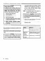
IMPORTANT
United States Government safety standards have been adopted under the Occupational Safety and Health Act. These
standards -particularly
the General Standards, Part 1910, and the Construction Standards, Pat-l 1926 -should be
consulted.
4
308-518
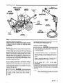
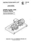
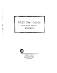
PUMP OIL LEVEL
INDICATOR
WINDOW
WATER
CONNECTION
-,-.. a-----.
S/4” UAHDEN
MOTOR
SWITCH
/
I
ELECTRIC
PLUG
\
ADJUSTABLE
NOZZLE (826)
\
HOSE (f)
SPRAY GUN
HIGH
QUICK
CONNECTION
INLET
FILTER
HIGH
PRESSURE \
SPRAY HOSE
PUMP
DIPSTICK
Figure 1
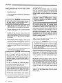
Check for Shipping Damage
Check the unit for any damage that may have occurred
in shipping. Note any damage and notify the carrier
immediately.
Set Up
Before plugging in the unit, be sure the electrical service
matches the specification in Technical Data (page 22 )
and the voltage label on the unit. With the unit off, plug
the power supply cord into a grounded, GFCI-protected
outlet. Do not remove the electrical plug which comes
with the unit or bend connecting prongs to fit an
improper outlet! Use an extension cord that meets the
requirements of the EXTENSlON CORD section and is
no more than 100 ft (30 m) long. Added length of cord
will affect current draw of unit.
If you are using a 1235 with a downstream chemical
injector, install it between the pump unloader and the
high pressure hose, using the quick couplers provided.
Connect the high pressure hose between the pump
outlet and the gun inlet.
Up to 100 ft (30 m) of high pressure hose may
performance, and chemical injector performance,
Install the appropriate spray tip on the wand of the 1235.
See Installing and Changing Spray Tips.
Connect to Water Supply
CAUTION
Before attaching to the water supply, check your
local plumbing code regarding cross- connection
to the water supply.
A backflow preventer P/N 801-l 33 is available to
prevent backflow of contaminated water into the
fresh water supply. Install it upstream from the
pump.
Install a regulating water valve, P/N 800-258,
inlet water pressure is over 60 psi (4.1 bar).
Do not exceed
temperature.
160”
F (70”
if
C) inlet water
Connect a hose with at least a 314 inch (19 mm) ID and
not longer than 50 ft (15 m) to the unit’s 3/4 inch garden
hose inlet.
NOTE:
The water source at the unit musl have a
minimum flow rate equal to that of the unit (see
Technical Data, page 22).
308-518
5
Use this procedure whenever starting the pressure
washer to help insure that the unit is ready to operate
and starting is done safely.
1.
Check the oil level.
Pump: Add SAE 20 or 30 weight non-detergent
as necessary.
2.
c
oil
Turn on the water supply.
Never run the unit dry. Costly damage to the pump
will result. Always be sure the water supply IS
completely turned on before operating.
3.
Trigger the gun until water sprays from the tip
indicating that the air is purged from the system.
4.
Plug the electrical cord into a proper, grounded,
GFCI-protected outlet.
5.
ALWAYS engage the gun’s trigger safety latch
whenever you stop spraying, even for a moment to
reduce the risk of fluid injection or splashing in the
eyes or on the skin if the gun is bumped or triggered
accidentally.
6.
Most pressure washer spraying is done at full
pressure. On this pressure washer there is an
adjustable unloader valve that permits operation at
less than maximum pressure. To reduce pressure,
for special cleaning applications, turn the pressure
control knob on the unloader counterclockwise, as
needed.
7.
ALWAYS observe the followinq CAUTIONS to avoid
costly damage to the pressu‘;e washer.
CAUTION
DO NOTallow the pressure washer to idle for more
than 10 minutes. Doing so may cause the
recirculating water to overheat and seriously
damage the pump. Turn off the pressure washer if it
will not be spraying or cleaning at least every 10
minutes. If heated inlet water is used, reduce this
time further,
DO NOT run the pump dry, which will quickly
damage the pump. Be sure the water supply is
fully turned on before starting the pump.
DO NOToperate the pressure washer with the inlet
water screen removed. This screen helps keep
abrasive sediment out of the pump, which could
clog or scratch the pump. Keep this screen clean.
DO NOT pump caustic materials; such materials
may corrode the pump components.
8.
6
See the chemical injector or kit manual for detailed
cleaning information if this accessory is used.
308-518
Chemical Injector
BE SURE that all chemicals used in the chemical
injector are compatible with the wetted pans of the
hose, gun, wand and tip, as given in the Technical Data
(page 22). Always read the chemical manufacturer’s
literature before using any chemical in this pressure
washer.
~ri~RK!rZa”““‘.l
precautrons regarding use of goggles, protectrve
826: A downstream chemical injector is provided with
the pressure washer. Insert the chemical strainer
(attached with clear tubing to the chemical injector) into
the container of chemical. Turn the control ring on the
adjustable nozzle clockwise. This causes a drop in
pressure that actuates the chemical injector. Close the
adjustable nozzle to deactivate the chemical injector
and produce high pressure for rinsing. The flowrate of
the chemical is regulated by turning the chemical
adjustment knob on the injector. Maximum chemical
flow is at a full two turns counterclockwise
from the
closed (clockwise) position.
1235: The chemical injector is an accessory. See the
chemical injector instruction manual.
WARNING
DO NOT attempt to open or close the adjustable
nozzle when the spray gun is in use. Be sure that
the trigger safety latch on the gun is in the “ON”
position before adjusting to avoid serious bodily
injury or fluid injection.
r
Check the distance that you will need to hold the spray
nozzle from the surface by test spraying on a scrap of
similar material. For soft surfaces, such as wood, hold
nozzle 3 ft (1 m) from the surface and gradually bring it
closer, checking to see if the high pressure spray is
damaging the surface.
Mist the wet surface with cleaning solution. Let it soak
briefly, then use the high pressure rinse to “chisel” off
the soil. Keep the nozzle at an angle to the surface and
at a distance determined to be best for the surface. If
some soil remains, repeat the procedure, letting the
chemical soak a little longer. Stubborn soil can be
cleaned off better with a stronger, heated cleaning
solution.
Protect surfaces that might be damaged by the cleaning
solution or the high pressure spray. Rinse the solution
before it dries.
Installing and Changing Spray Tips (1235)
Trigger Safety Latch
WARNING
WARNING
To reduce the risk of serious bodily injury,
including fluid injection, splashing in the eyes or
on the skin, ALWAYS engage the trigger safety
latch whenever spraying stops, even for a
moment.
To reduce the risk of serious bodily injury,
including fluid injection or splashing in the eyes or
onto the skin, use extreme caution when changing
spray tips. ALWAYS follow the procedure below.
In the engaged position, the trigger safety latch
prevents the gun from being triggered accidentally
by hand or if it is dropped or bumped. Be sure the
latch is pushed fully down when engaging it or it
cannot prevent the gun from being triggered. See
Figure 2.
TRIGGER SAFETY
LATCH SHOWN
ENGAGED
1.
Follow the Pressure Relief Procedure.
2.
Point the gun and wand away from yourself and
anyone else.
3.
Without holding your hand over the spray tip (A),
pull back the quick coupler ring (B), remove the tip
and then release the ring. See Figure 3.
4.
Be sure the tip is secure before starting to spray
again.
5.
Tip holding holes are provided on the chassis.
’
\
\:
TRIGGER SAFETY
LATCH SHOWN
DISENGAGED
Figure 2
Figure 3
308-518
7
SHUTDOWN,
FLUSHING
AND STORAGE
WARNING
1.
Pressure Relief Procedure
To reduce the risk of serious bodily injury,
including fluid injection and splashing in the eyes,
or on the skin, always follow this procedure
whenever you stop spraying for more than 10
minutes, when shutting down, and before
checking or repairing any part of the system.
1.
Engage the trigger safety latch.
2.
Turn the sprayer off.
3.
Disconnect the electrical supply.
4.
Shut off the water supply.
5.
Disengage the trigger safety latch and trigger
the gun to relieve pressure, and then engage
the trigger safety latch again.
6.
Before
long-term
(overnight)
storage,
disconnect the water supply and disconnect
the electricity.
MAINTENANCE
There is a break-in period for the pump. After changing
the oil initially, the interval between required changes is
longer.
WARNING
To reduce the risk of serious bodily injury,
including fluid injection, splashing in the eyes or
on the skin or injury from moving pans, always
follow the Pressure Relief Procedure Warning
before proceeding.
308-518
NOTE:
An anti-freeze flush kit P/N 802-327
available to make flushing easier.
is
CAUTION
If water does freeze in the pressure washer, thaw it
in a warm room before trying to start it. DO NOT
pour hot water on or into the pump; it may crack the
ceramic plungers!
2.
After each use, wipe all surfaces of the pressure
washer with a clean, damp cloth.
3.
Perform the appropriate
maintenance chart.
maintenance.
See the
I___
Observing regular maintenance intervals helps ensure
that you get maximum performance and life from the
pressure washer.
8
If the pressure washer will be exposed to freezing
temperatures, drain all water out of the pump. If it
must be stored in freezing temperatures, flush the
unit with a 50% anti-freeze
solution. Relieve
pressure. Flush the pressure washer before using it
again to remove the anti-freeze.
Interval
What to do
Daily
Clean water inlet screen and
filter. Check pump oil level. Fill
as necessary.
After first 50
hours of
operation
Change pump break-in oil. Use
SAE 20 or 30 non-detergent oil.
Each 500 hours
of operation or
6 months
Change pump oil. Use SAE 20 or
30 non-detergent oil.
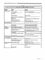
TROUBLESHOOTING
CHART
WARNING
To reduce the risk of serious bodily injury, including fluid injection, splashing in the eyes or on the skin, or injury from
moving parts, always follow the Pressure Relief Procedure Warning before proceeding.
8
I
Problem
Cause
-0w pressure and/or
,ump runs rough
Worn or wrong size tip,
Replace with tip of proper size.
Inlet filter clogged.
Clean. Check more frequently.
Check filter. Replace packings. See PUMP SERVICE.
Solution
Worn packings, abrasives in water or
natural wear.
Inadequate water supply.
Coupling slippage.
Fouled or dirty inlet or discharge valves.
Even a small particle can cause the valve
to stick.
Restricted inlet.
Check water flow rate to pump.
Tighten or replace.
Clean inlet and discharge valve assemblies.
filter.
Check
Worn inlet or discharge valves.
Leaking high pressure hose.
Check garden hose, may be collapsed
Replace worn valves.
Replace high pressure hose.
Nater leakage from
under pump manifold
Worn packings.
Install new packings. See PUMP SERVICE.
Nater in pump
Humid air condensing
Worn packings.
Oil seals leaking.
?equent or
Iremature failure of
he packings
Scored, damaged or worn plungers.
Abrasive material in the fluid being pumped.
Install new plungers. See PUMP SERVICE.
Install proper filtration on pump inlet plumbing.
Inlet water temperature too high.
Overpressurizing pump.
Excessive pressure due to partially plugged
or damaged tip.
Check water temperature; may not exceed 160°F
Do not modify any factory-set adjustments. See
EQUIPMENT MISUSE HAZARD.
Clean or replace tip. See Installing and Changing Spray
Tips.
Pump funning too long without spraying.
Never run pump more than 10 minutes without spraying
inside crankcase.
or kinked.
Change oil as specified in MAINTENANCE.
Install new packings. See PUMP SERVICE.
Install new oil seals. See PUMP SERVICE.
Do not run pump without water.
Running pump dry.
Strong surging at the
nlet and low pressure
on the discharge side
Foreign particles in the inlet or discharge
valve or worn inlet and/or discharge valves.
Clean or replace valves. See PUMP SERVICE.
Jnit will not start
Unit not plugged in.
Electrical service off/GFCI activated.
Check power cord.
Thermal overload has tripped.
Chemical injector will
lot siphon
Chemical
injector clogged.
Adjustable nozzle completely
Low chemical level.
Wrong tip (1235).
closed (826).
Check fuse/circuit breaker. Check for proper
grounding.
Press reset button on motor.
Disassemble chemical valve and clean. Check and
clean chemical hose and filter.
Turn control ring on nozzle clockwise to cause drop in
pressure.
Check level of chemical
Install chemical tip.
308-518
9
1. Loosen the plunger retaining screw five to six turns,
To reduce the risk of serious
including fluid injection, splashing
NOTE:
The following metric wrenches are needed:
MlO, Ml3 and M30. Repair kits are available.
Refer to the individual repair sections and the
pump parts page for more details. For the best
results, use all parts in the kits.
NOTE:
Valves
NOTE:
There are two different tool kits to aid in
servicing the pump. P/N 800-298 is used to
ease installation of packings. P/N 800-271
includes the items in 800-298 and tools to aid
in the removal of packing retainers.
Remove the hex plug from the manifold using an
M30 wrench.
2.
Examine the o-ring under the hex plug and replace
it if it is cut or distorted.
3.
Remove the valve assembly
assembly may come apart.
4.
Install the new valve. Install the o-ring and hex plug;
torque to 75 fl-lb (103 Nm).
Remove the screw from the plunger and examine
the o-ring, backup ring and copper bearing/gasket
washer. Replace these parts if necessary using kit
801-474.
3.
Remove the plunger and flinger from the plunger
shaft. Clean, examine and replace parts as
necessary.
4.
Inspect the plunger shaft for oil leakage from the
crankcase. If leaking is obvious, replace the oil
seals. Otherwise, DO NOT remove these seals as
they cannot be reused. An oil seal kit is available to
replace the seals.
5.
Lightly grease the oil seal, if it is being replaced,
and the flinger and replace them on the plunger
shaft. Then install the plunger.
6.
Lightly grease the retaining screw and the outer end
of the plunger. Place the washer, o-ring and backup
ring around the screw and install the screw through
the plunger. Torque to 14.4 ft-lb (19.5 Nm).
NOTE:
from the cavity; the
Retorque the plug after 5 hours of operation.
Pumping Section
1.
Remove the eight capscrews and Iockwashersfrom
the manifold using an Ml 3 wrench.
2.
Carefully separate the manifold from the crankcase.
NOTE:
2.
For a set of six valves, order P/N 801-472.
1.
NOTE:
using an Ml 0 wrench. Push the plunger towards the
crankcase to separate the plunger and retaining
screw.
bodily injury,
in the eyes or
Lubricate the outside of each plunger. Slide the
manifold onto the crankcase, being careful not to
damage the seals.
8.
Install the capscrews and washers finger-tight.
Torque the screws to 21.7ft-lb (29 Nm) following the
tightening pattern (Figure 4). Uneven tightening
may cause the manifold to bind or jam.
It may be necessary to tap the manifold lightly
with a soft mallet to loosen.
1
CAUT’oN
I
Carefully examine each plunger for any scoring or
cracking and replace as necessary,
Servicing
NOTE:
the Plungers
Plunger repair kit, P/N 801-474 is available to
replace retainers, o-rings,
washers and
backup rings for three cylinders.
1-O 308-518
refer to
7.
Keep the manifold properly aligned with the
ceramic plungers when removing to avoid
damage to the plunger or seals.
3.
If you plan to replace the packings,
Servicing the V-Packings.
Figure 4
Servicing the V-Packings
NOTE:
There are two types of packing kits: one is just
packings, the other includes the packings,
rings and retainers.
1.
Remove the manifold as outlined in the Pumping
Section.
2.
Carefully pull the packing retainer from the
manifold. Examine the o-ring and replace it if it is
cut or damaged.
3.
Remove the v-packing and head ring. Pull out the
intermediate retainer ring. Remove the second
v-packing and second head ring.
4.
5.
Thoroughly
examine.
clean
the
packing
cavities
and
6.
Lightly grease the packing cavities and then
replace the packings in the following order: head
ring, v-packing,
intermediate ring, head ring,
v-packing and packing retainer with the o-ring
installed in the retainer groove.
7.
Reassemble the manifold as instructed in Servicing
the Plungers.
Inspect all parts and replace as necessary.
308-518
11
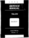
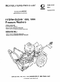
800-093 Hydra-Clean@ 826 Pressure Washer
115 VOLT, 1 PHASE
-
-27
,.-
/
26
WHT
-I--BLK
GRN
--
*
\yL-EL
32
MOTOR /
WIRING
BOX
69
~~
T8
12
308-518
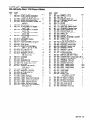
800-093 Hydra-Clean@ 826 Pressure Washer
REF
NO.
PART
NO.
1
801-683
803-059
801-881
801-901
801-023
801-025
801-940
5
z
6
7
i;
18
19
20
21
27
28
3’:
31
32
33
DESCRIPTION
STRAINER, Chemical
TUBING, Vinyl
SWIVEL,1/4 NPSM x 3/8 NPT
BRACKET, Support
WASHER, Flat 5/l 6
WASHER, Lock 5/l 6
SCREW, Cap, hex hd
5/16-18 x 3/4
801-900 GROMMET Rubber
803-486 INJECTOR, Chemical
801-905 ADAPTER, 3/8 6 x 318 NPT
801-907 WASHER, Flat
801-865 UNLOADER, 800 PSI
801-880 PIN, Cotter l/8 x 1-l/2
801-890 SWIVEL, 3/8 NPSM x 3/8 NPT
801-891 NIPPLE, Hex,
3/8 NPSM x 3/8 NPT
801-178 ELBOW, Street 3/8
801-709 PLUG, Square Head l/4
801-866 HOSE BYPASS (incl28)
801-024 NUT Hex 5/16-18
801-539 BUMPER
801-941 SCREW, Cap, hex hd
5/16-18x 1
108-179 WHEEL & TIRE ASSEMBLY
801-235 WASHER, Flat
80 l-857 AXLE
800-426 CHASSIS
801-546 SCREW, Cap, hex hd
3/8-16x l-1/4
801-015 WASHER, Flat 3/8
802-627 NIPPLE, Hex
3/8 NPSM x l/4 NPT
800-l 18 NOZZLE, Adjustable
801-363 WASHER, Lock 3/8
801-878 NUT, Hex 3/8-l 6
800- 175 FRONT LEG ASSEMBLY
HirKly~es
26, 27, 48, 49,50)
801-541
QTY
REF
NO.
PART
NO.
8’ ft
iz
1
36
1:
8
4
1
ii
39
40
41
42
801-967
402-278
801-112
801-110
801-111
801-090
801-935
801-957
800- 154
:
43
800-396
z
46
47
801-666
803-350
801-103
801-009
:
2
1
;
48
:
4
1
3:
53
4
4
1
1
z
56
57
58
59
:i
150
1
1
4
4
1
1
E
66
67
:9”
70
101-566
80 l-504
801-858
803-l 85
803-l 55
803-309
801-937
802-765
161-162
801-612
105-659
803-l 65
803-396
801-008
803-083
803-308
801-226
802-l 36
801-202
800-376
DESCRIPTION
QTY
1
HOSE, High Pressure 30’
1
PLUG, Plastic
STRAINER, Garden Hose
:
ADAPTER, Garden Hose
1
NUT, Garden Hose
QUICK COUPLER, Male l/4
:
WAND. 20”
1
SLEEVE, i 8”
PUMP & MOTOR ASSEMBLY
1
(see page 16)
GUN & WAND ASSEMBLY
(incl 29, 40, 41, 45, 46, 47)
:
TIP, Spray, 15 degree
1
GUN, Spray
1
NIPPLE, Hex l/4 x 3/8
QUICK COUPLER, Female l/4
1
(incl 70)
NUT Hex Lock 3/8-l 6
:
BUMPER, Rubber
1
BRACKET, Front Leg
1
LABEL, Warning, cordset
1
CORD SET, GFCI
1
SWITCH, Toggle
NUT, Lock, electrical
:
CORD GRIP
1
WASHER, Rubber
1
WASHER, Flat
1
COVER, Toggle Switch
1
LABEL, Caution, 115V
LABEL, Caution/Warning
:
LABEL, Grace G
LABEL, Keep from Freezing
;
TERMINAL, Slide
CONNECTOR, Wire
TERMINAL, Slide
i
O-RING, Female coupler, l/4
1
HOSE ASSEMBLY, w/Quick Couplers
(incl 34, 39, and l/4 female QC)
308-518
13
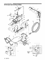
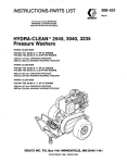
PARTS DRAWING
800-268 Hydra-Clean@ 1235 Pressure Washer
62
MOTOR
.
56
57
58
59
230 VOLT, 1 PHASE
5
37
39
,/----7
1
\
/
\
/
/
,’
I
'
b'
i
I
50I
L\
I
I
14
16
I
308-518
*-79
i
17 I %-
i
17
1
L-----lb----+ _I
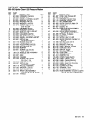
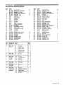
800-268 Hydra-Clean@ 1235 Pressure Washer
REF
NO.
1
PART
NO.
DESCRIPTION
800-394 GUN & WAND ASSEMBLY
2
3
4
801-090
801-007
801-009
5
6
7
8
9
10
11
12
13
14
2
17
18
(incl
QUICK
HOSE,
QUICK
4,13, 49, 50, 54)
COUPLER, Male l/4
High Pressure 50’
COUPLER, Female l/4
402-278 PLfZt Xstic
800- 135 TIP AiSEMBLY,
(incl2, 74)
800- 134 TIP ASSEMBLY,
(incl 2, 75)
800-060 TIP ASSEMBLY,
(incl 2, 76)
800-061 TIP ASSEMBLY,
801-012
801-541
800-374
REF
PART
NO.
3”70-
801-523
801-106
801-l 78
800-l 15
802-666
800- 113
801-l 11
801-l 10
801-l 12
801-866
801-620
802-842
801-935
801-957
801-890
801-891
QlY
{
3
1
0 Degree
1
15 Degree
1
25 Degree
41
42
43
44
45
46
47
48
1
9:
40 Degree
G#%t?E??Rubber
HANDLE ’
HOSE ASSEMBLY w/Quick
Couplers (incl2, 3, 4)
803-350 GUN, Spray
800- 175 FRONT LEG ASSEMBLY
(incl 17, 18, 78, 79, 80)
801-878 NUT Hex 3/8-l 6
801-363 WASHER, Lock 3/8
801-015 WASHER, Flat 3/8
801-546 SCREW, Cap, hex hd
3/8-16x l-1/4
800-274 CHASSIS
802-l 39 AXLE
801-235 WASHER, Flat
106-062 WHEEL & TIRE ASSEMBLY
801-880 PIN, Cotter 1/8x l-1/2
104-811 HUB CAP
801-941 SCREW, Cap, hex hd
5/16-18x 1
801-023 WASHER, Flat 5/l 6
801-025 WASHER, Lock 5/l 6
801-024 NUT, Hex 5/l 6-l 8
801-539 BUMPER
801-008 LABEL, Grace G
176-250 LABEL, Warning
803-083 LABEL, Keep From Freezing
803-396 LABEL, Caution & Warning
80 l-445 LABEL, Caution 230 Volt
803-l 86 LABEL, Warning Cordset
800-248 PUMP & MOTOR ASSEMBLY
(see page 17)
1
4
1
:;
801-709
801-103
803-262
803-263
802-732
802-731
801-633
801-227
1
1
1
4
1:
803-021
801-929
801-930
801-221
801-304
801-226
801-303
801-228
801-229
801-937
801-931
803-149
802-627
8
12
8
4
:
1
1
1
1
1
1
74
75
76
77
si
80
801-665
801-666
801552
801-553
101-556
801-504
801-858
QTY
DESCRIPTION
NIPPLE, l/2 x 2
1
TEE, l/2
1
ELBOW, Street l/2
THERMAL RELIEF VALVE
:
TEE, Street
FILTER
i
NUT, Garden Hose
1
ADAPTER, Garden Hose
1
STRAINER, Garden Hose
HOSE, Bypass (incl73)
:
ELBOW, Street l/4
1
UNLOADER, 1200 PSI
1
WAND, 20”
1
SLEEVE, 18”
1
SWIVEL, 3/8 NPSM x 3/8 NPT
1
NIPPLE, Hex
3/8 NPSM x 3/8 NPT
PLUG, Square Head l/4
i
NIPPLE, Hex 3/8 x l/4
2
BRACKET, Switch Right
1
BRACKET, Switch Left
1
WASHER, Flat #6
4
WASHER, Lock #6
4
NUT, Hex #6-32
4
SCREW, Machine,
round hd #6-32 x 3/4
4
1
SWITCH, 230 Volt 1 Phase
CONNECTOR, Conduit 3/8 x 90” 2
CONDUIT, Sealtight 3/8
7 in
TERMINAL, Ring #lO
1
TERMINAL, Ring #8
1
CONNECTOR, Wire
4
WIRE, 14AWG Green
18 in
WIRE, 14AWG Black
18 in
WIRE, 14AWG White
18 in
NUT, Lock Electrical
1
CORD GRIP
1
CORD SET
1
NIPPLE, Hex
3/8 NPSM x l/4 NPT
1
TIP, Spray 0 Degree
1
TIP, Spray 15 Degree
TIP, Spray 25 Degree
:
TIP, Spray 40 Degree
1
NUT, Lock 3/8-l 6
1
BUMPER, Rubber
1
BRACKET, Front Leg
1
308-518
15
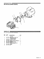
PARTS DRAWING
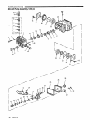
800-154 Pump and Motor Assembly
PARTS LIST
800-154 Pump and Motor Assembly
REF
NO.
1
2
3
4
2
i
9
10
11
12
16
PART
NO.
DESCRIPTION
QTY
MOTOR, 1.5 hp TEFC, 1 phase
(incl 12)
1
801-864 PUMP, 800 psi (see parts
drawing, page 18)
1
801-870 HOUSING, Coupler
801-871 COUPLER (incl 11)
SCREW, Cap, hex hd M6 x 20
801-023 WASHER, Flat ,1/4
801-872
WASHER, Lock, l/4
801-015 WASHER, Flat, 5/16
801-139
801-363 WASHER. Lock. 318
802-818 BOLT, Hex Hd, $8-16 x 1
801-887 SPIDER
801-l 37 KEY
801-862
308-518
PARTS DRAWING
800-248 Pump and Motor Assembly
PARTS LIST
800-248 Pump and Motor Assembly
REF
NO.
PART
NO.
1
802-625
2
802-629
3
2
6
7
8
802-633
802-698
802-786
801-139
802-784
802-785
9
10
801-887
801-137_
DESCRIPTION
MOTOR, 3.0 hp TEFC, 1 phase
(incl 10)
PUMP, 1200 psi (see parts
drawing, page 20)
HOUSING, Coupler
COUPLER (incl 9)
SCREW, Cap, hex hd M6 x 16
WASHER, Lock l/4
WASHER, Lock l/2
SCREW, Cap, socket hd
1/2-13x l-1/4
SPIDER
KEY
QTY
1
1
1
:
4
4
4
1
1
308-518
17
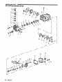
PARTS DRAWING
802-285 Pump Assembly, 800 psi
11-i
18
I
I
I 7
6
I
d
14
-
1
I
I
18
308-518
PARTS LIST
802-265 Pump Assembly, 800 psi
REF
NO.
1
2
3
4
5
6
7
8
9
10
11
12
13
14
15
16
17
18
19
20
21
22
23
24
Kit
No.
PART
NO.
DESCRIPTION
801-899
802-795
801-651
801-652
KIT 1
KIT 1
KIT 1
KIT 1
KIT 1
KIT 4
KIT 4
KIT 1
KIT 19, 27
KIT 27
KIT 27
KIT 27
KIT 27
KIT 23
803-265
803-266
803-267
803-268
803-269
803-270
801-659
Repair Kit
Part No.
801-472
Valve
MANIFOLD, Aluminum
MANIFOLD, Brass
SCREW, Cap, socket hd.
WASHER, Lock
O-RING
SEAT, Valve
PLATE, Valve
SPRING
GUIDE, Valve
O-RING
CAP
VALVE ASSEMBLY
PACKING
RETAINER, Packing
RING, Head
RETAINER, Packing
O-RING
SEAL, Oil
SCREW, Cap, hex hd
COVER, Crankcase
SPACER
O-RING
BEARING, Ball
CRANKCASE
DIPSTICK
801-474
Plunger
Repair
1
1
6
6
Ref
No.
Description
4
5
6
7
8
11
O-ring
Seat, valve
Plate, valve
Spring
Guide, valve
Valve Assy.
6
6
6
6
6
6
6
6
28
41
42
43
O-ring
Cap
O-ring
Ring, backup
Washer
Screw, piston
3
3
3
3
Packing
6
Seal, oil
6
Packing
Retainer, packing
Ring, head
Retainer, packing
O-ring
1
1
1
1
1
802-306
Valve Cap
6
QTY
801-662
REF
2.
26
27
28
29
30
31
32
33
34
35
36
37
38
39
40
41
42
43
44
45
49
50
51
52
PART
NO.
803-271
803-272
803-273
KIT 6
802-345
802-793
803-274
803-275
802-794
803-276
803-277
803-278
803-279
803-280
801-489
801-661
KIT 6
KIT 6
KIT 6
803-281
803-282
801-484
801-482
801-483
801-485
QTY
DESCRIPTION
GASKET, Cover
COVER, Crankcase
SCREW, Cap, socket hd.
O-RING
GAUGE, Sight
PLUG, Oil Drain
CRANKSHAFT
PIN, Wrist
KEY
ROD, Connecting
WASHER, Flat
WASHER, Lock
SCREW, Cap, socket hd.
GUIDE, Piston
WASHER, Flinger
PLUNGER, Ceramic
RING, Backup
WASHER
SCREW, Piston
SPACER
SEAL, Crankshaft
PLUG, Hex
PLUG, Hex
WASHER, Flat
WASHER, Flat
1
1
4
1
1
1
2
1
2
4
4
4
2
2
2
QtyIncl.
Packing
23
801-658
Oil Seal
27
801-664
Packing &
Retainer
12
13
14
15
16
308-518
19
PARTS DRAWING
802-629 Pump Assembly, 1200 psi
I
I
20
308-518
802-629 Pump Assembly, 1200 psi
REF
NO.
1
2
3
4
5
6
;
9
10
11
12
13
14
15
16
17
18
19
20
21
22
23
24
25
Kit
No.
PART
NO.
DESCRIPTION
802-319
801-651
801-652
KIT 1
KIT 1
KIT 1
KIT 1
KIT 1
KIT 4
KIT 4
KIT 1
KIT 19, 27
KIT 27
KIT 27
KIT 27
KIT 27
KIT 23
803-265
803-266
803-267
803-268
803-269
803-326
801-659
803-327
1
8
8
MANIFOLD, 1200 psi
SCREW, Cap, socket hd.
WASHER, Lock
O-RING
SEAT, Valve
PLATE, Valve
SPRING
GUIDE, Valve
O-RING
CAP
VALVE ASSEMBLY
PACKING
RETAINER, Packing
RING, Head
RETAINER, Packing
O-RING
SEAL, Oil
SCREW, Cap, hex hd
COVER, Crankcase
SPACER
O-RING
BEARING, Ball
CRANKCASE
DIPSTICK
GASKET, Cover
Repair Kit
Part No.
801-472
Ref
No.
4
Valve
5
6
7
8
11
802-306
Valve Cap
9
10
Description
REF
PART
NO.
DESCRIPTION
!I?
27
28
29
30
31
32
33
34
35
36
37
38
39
40
41
42
43
44
45
49
50
51
52
802-526
803-273
KIT 6
802-345
802-793
803-329
803-275
802-794
803-276
803-277
803-278
603-279
803-330
801-660
801-661
KIT 6
KIT 6
KIT 6
803-281
803-282
801-484
801-482
801-483
801-485
COVER, Crankcase
SCREW, Cap, socket hd.
O-RING
GAUGE, Sight
PLUG, Oil Drain
CRANKSHAFT
PIN, Wrist
KEY
ROD, Connecting
WASHER, Flat
WASHER, Lock
SCREW, Cap, socket hd.
GUIDE, Piston
WASHER, Flinger
PLUNGER, Ceramic
RING, Backup
WASHER
SCREW, Piston
SPACER
SEAL, Crankshaft
PLUG, Hex
PLUG, Hex
WASHER, Flat
WASHER, Flat
QTY
QPY
5
1
1
i
1
3
6
6
6
3
3
3
QW
Incl.
O-ring
Seat, valve
Plate, valve
Spring
Guide, valve
Valve Assy.
O-ring
Cap
O-ring
Ring, backup
Washer
Screw, piston
801-474
28
Plunger
Repair
41
42
43
1
1
19
801-662
Packing
I12
1Packing
23
801-658
6
6
17
Seal, oil
6
801-664
12
Packing &
Retainer
13
14
15
16
Packing
Retainer, packing
Ring, head
Retainer, packing
O-ring
1
1
1
1
1
Oil Seal
27
308-518
21
ACCESSORIES
(Must be purchased separately)
ANTI-FREEZE FLUSH KIT 802-327
DOWNSTREAM CHEMICAL INJECTOR KIT
(1235) 800-l 11
For injecting harsh cleaning
from the pump.
chemicals
downstream
For flushing system with 50% anti-freeze solution prior
to transporting or storing pressure washer in below
freezing temperatures.
INLET PRESSURE REGULATOR 800-258
UPSTREAM CHEMICAL INJECTOR KIT
600-257
For injecting mild cleaning chemicals upstream into the
pump.
Regulates
maximum.
inlet water
pressure
to 60 psi (4 bar)
BACKFLOW PREVENTOR 801-133
Prevent back-up of contaminated
supply. Install upstream of pump.
TECHNICAL
water into fresh
DATA
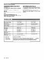
Model 800-093
Model 800-268
inotor (Totally Enclosed
-an Cooled)
1.5 hp, 1 phase
3.0 hp, 1 phase
:lectrical Service
115 volt/l5
230 volt/20 amps/60 Hz
Vater Pump Maximum
Vorking Pressure
800 psi (55 bar)
1200 psi (82 bar)
amps/60 Hz
2.6 gpm (10 Ipm)
3.5 gpm (13 Ipm)
Jnit Weight
90 Ibs (41 kg)
140 Ibs (64 kg)
Iimensions
Length
Width
Height
36 in (991 mm)
19 in (482 mm)
20 in (508 mm)
39 in (991 mm)
21 in (533 mm)
21 in (533 mm)
vlaximum Inlet Water
remperature
160” F (70” C)
160” F (70” C)
nlet Hose Connection
3/4 in garden hose (f)
3/4 in garden hose
nlater Pump Maximum
Netted Pans
High Pressure Hose
Flow
Acrylonitrile
and Buna-N cover and tube
Bypass Hose
Synthetic yarn and EPDM
Pressure Washer
(including fittings)
Anodized aluminum, Aluminum or Bronze alloys, Brass, Copper, Nylon-T composite,
Ceramic, Buna-N, Cotton Phenolic, 303, 304, and 316 Stainless Steel, Polymide-12
Thermoplastic, @, Carbon Steel, Zinc with or without Yellow Chromate Plate P
egistered
22
(9
308-518
trademark of the DuPont Company
THE GRACO WARRANTY
WARRANTY AND DISCLAIMERS
Grace warrants all equipment manufactured by it and bearing its name to be free from defects in material
and workmanship on the date of sale by an authorized Grace distributor to the original purchaser for use.
As purchaser’s sole remedy for breach of this warranty, Grace will, for a period of twenty four months from
date of sale, repair or replace any part of the equipment proven defective. This warranty applies only when
the equipment
is installed, operated and maintarned in accordance
with Grace’s written
recommendations.
This warranty does not cover, and Grace shall not be liable for, any malfunction, damage or wear caused
by faulty installation, misapplication, abrasion, corrosion, inadequate or improper maintenance,
negligence, accident, tampering, or substitution of non-Grace component parts. Nor shall Grace be
liable for malfunction, damage or wear caused by the incompatibility with Grace equipment of structures,
accessories, equipment or materials not supplied by Grace. or the improper design, manufacture,
installation, operation or maintenance of structures, accessories, equipment or materials not supplied by
Grace.
This warranty is conditioned upon the prepaid return of the equipment claimed to be defective for
examination by Grace to verify the claimed defect. If the claimed defect is verified, Grace WIII repair or
replace free of charge any defective parts. The equipment will be returned to the original purchaser
transportation prepaid. If inspection of the equipment does not disclose any defect in material or
workmanship, repairs will be made at a reasonable charge, which charges may include the costs of parts,
labor and transportation.
DISCLAIMERS AND LIMITATIONS
THE TERMS OFTHIS WARRANlY CONSTITUTE THE PURCHASER’S SOLE AND EXCLUSIVE REMEDY
AND ARE IN LIEU OF ANY OTHER WARRANTIES (EXPRESS OR IMPLIED). INCLUDING WARRANlY OF
MERCHANTABILITY OR WARRANTY OF FITNE‘SS FOR A PARTlCUtiR
PURPOSE, AND OF ANY
NON-CONTRACTUALLIABILITIES.
INCLUDING PRODUCT LIABILITIES. BASEDON NEGLIGENCEOR
STRICT LlABlLllY EVERY FORti OF LIABILITY FOR DIRECT. SPiClAL OR CONSEQUENTIAL
DAMAGES OR LOSS IS EXPRESSLY EXCLUDED AND DENIED. IN NO CASE SHALL GRACO’S
LIABILITY EXCEED THE AMOUNT OF THE PURCHASE PRICE. ANY ACTION FOR BREACH OF
WARRANTY MUST BE BROUGHT WITHIN THREE (3) YEARS OF THE DATE OF SALE.
EOUIPMENT NOT COVERED BY GRACO WARRANTY
GRACO MAKES NO WARRANP/ AND DISCLAIMS ALL IMPLIED WARRANTIES OF MERCHANTABILITY
AND FITNESS FOR A PARTICULAR PURPOSE, WITH RESPECT TO ACCESSORIES, EQUIPMENT.
MATERIALS OR COMPONENTS SOLD BUT NOT MANUFACTURED BY GRACO. These items sold, but
not manufactured by Grace (such as electric motor, switches, hose, etc.) are subject to the warranty, if
any, of their manufacturer. Grace WIII provide purchaser with reasonable assistance in making any claim
for breach of these warranties.
IMPORTANT
PHONE NUMBERS
TO PLACE AN ORDER, contact your Grace distributor,
distributor closest to you: l-800-328-0211
Toll Free
FOR TECHNlCAL
application
Subsidiary
ASS/STANCE,
of Grace equipment:
service repair
l-800-543-0339
or call this number
information
Toll Free
or assistance
to identify
the
regarding
the
Factory Branches: Atlanta, Chicago, Dallas, Detroit, Los Angeles, West Caldwell (N.J.)
and Affiliate Companies: Canada; England; Switzerland; France; Germany; Hong Kong; Japan
GRACO INC. P.O. BOX 1441 MINNEAPOLIS,
PRINTED IN U.S.A. 308-518
2/90
MN 55440-1441