1
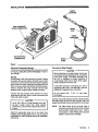
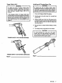
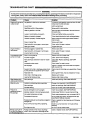
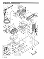
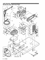
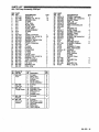
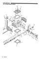
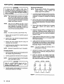
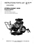
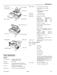
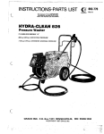
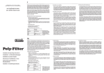
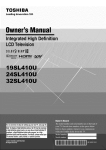
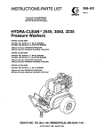
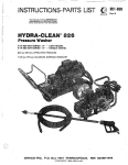
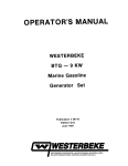
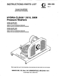
INSTRUCTIONS-PARTS LIST
This manual contains IMPORTANT
WARNINGS and INSTRUCTIONS
READ AND RETAIN FOR REFERENCE
HYDRA-CLEAN 2510.3009
Pressure Washer
@
I
HYDRA-CLEAN@2510
PIN 800-666, Series A
2500psi (172bar) OPERATING PRESSURE
2900psi (200 bar) MAXIMUM WORKING PRESSURE
HYDRA-CLEAN@' 3009
P/N 800-668, Series A
3000 psi (207 bar) OPERATING PRESSURE
3400 psi (234 bar)MAXIMUM WORKING PRESSURE
GRACO INC. RO. BOX1441 MINNEAPOLIS, MN 55440-1441
@COPYRIGHT1991, GRACO INC.
WARNING
HIGH PRESSURE SPRAY CAN CAUSE
SERIOUSINJURY.
FOR PROFESSIONALUSE ONLY. OBSERVE ALL WARNINGS.
Read and understand all instruction manuals before operating equipment.
FLUID INJECTION HAZARD
General Safety
Pressure Relief Procedure
This
pressure
washer
generates
very
high fluid
pressure.Sprayfrom
the gun, leaks orruptured
components can injectfluid through your skin and into
your body and cause extremely serious bodily injury
including theneed for amputation.Also, fluid injectedor
splashed into the eyesor on the skin can cause serious
damage.
To reduce the risk of serious bodily injury, including fluid
injection and splashing in theeyesor on theskin,
alwaysfollowthisprocedure
whenever you stop
sprayingfor more than10 minutes, when shuttingdown,
and before checking
or repairingany part of the system.
N N E R point the spray gun or wand at anyone
at any
or
part of the body. NNER put hand or fingers over the
spray tip.
2. Tum the sprayer off.
ALWAYS follow the Pressure Rellef Procedure, before
cleaning or servicing any part ofthe sprayer.
4. Shut off the water supply.
N N E R try to stop or deflect leaks with your hand or
body.
Be sureequipmentsafetydevicesareoperating
properly before each use.
Medical Treatment
If any fluid appearstopenetrateyourskin,get
EMERGENCYMEDlCALTREATMENTATONCE.DO
CUT. Tell the doctor exactly
NOT TREAT AS A SIMPLE
what fluid was injected.
NOTE TO PHYSICIAN: Injection in the skin is a
traumatic injuv. It is Important to treat the Injury
surgically a s soon as posslble. Do not delay
treatmentto
research toxicity Toxicity is a
concern with someexotic coatings injected
directly into the bloodstream. Consultation with a
plastic surgeon or reconstructive hand surgeon
may be advisable.
2
308-528
1. Engage the trigger safety latch.
3.
Remove the ignition cable from the spark plug.
5. Disengage the trigger safety latch and trigger the
gun to relieve pressure, and then engage the trigger
safety latch again.
6. Before
long-term
(overnight) storage or
transporting of the unit, disconnect the water supply
and disconnectthe fuel supply.
Spray Gun Safety Devices
Be sure all gun safety devices are operating properly
before eachuse. Do not remove ormodify any part of
thegun; this can cause a malfunction and result
in
sefious bodily injury.
SAFETY LATCH: Whenever you stop spraying fora
moment, always set the gun safety
latch in the engaged
or "safe" position, makingthe gun inoperative. Failure
to
properly set the safety latch can result in accidental
triggering of thegun.
SPRAY TIP SAFEPI: Use
extreme
caution when
cleaning or changing spray tips. If a spray tip clogs
while
spraying,
engage
the
gun
safety
latch
immediately. ALWAYS follow the Pressure Relief
Procedure and then remove the spray
tip to clean it,
FUEL AND EMISSION HAZARDS
NNER fill the fueltank while the unitis running or hot.
me fuel used in thisunit is combustible and when
spilled on a hot surface can ignite and cause a fire.
ALWAYS fill tank slowly to avoid spilling.
N N E R operatetheunit
in a closed building. The
exhaust containscarbonmonoxide,apoisonous,
odorless, invisible gas whichcan cause serious injury
or death if inhaled.
N N E R alterthemaximumthrottlesetting,
which is
factory set. Tampering with this adjustment can damage
the pressure washer andwill void the warranty.
EQUIPMENT MISUSEHAZARD
General Safety
Any misuse of the pressure washer or accessories,
such
as
overpressurizing,
modifying
parts,
using
incompatible chemicals and fluids, or using wom or
in
damaged parts, can cause
them to rupture and result
fluid injection, splashing inthe eyes or on the skin, or
other serious bodily injury, fire, explosion or property
damage.
NNER alter or modify any part of this equipment; doing
so could cause it to malfunction.
CHECK all sprayequipmentregularlyandrepair
replace wom or damaged parts immediately.
recommendations on additional protective equipment,
such as a respirator.
System Pressure
n i s sprayer can develop high operating pressures.Be
sure thatall spray equipment and accessories rated
are
to withstand the maximum working pressure of this
sprayer. DO NOT exceedthemaximumworking
pressure of any component or accessory used in the
system.
Chemical Compatibility
or
BE SURE that ail chemicalsused in thechemical
injector are compatible with the wetted parts of the
hose, gun, wand andtip, as given in the Technical Data
ALWAYS wear protective eyewearandappropriate
(inside back cover).
Always
read
the
chemical
any chemical in
clothing. If usingachemical injector, readandfollowmanufacturer'sliteraturebeforeusing
the
chemical
manufacturer's
literature
for
this pressure washer.
HOSE SAFETY
~..
High pressurefluid in the hoses can be verydangerous.
If the hose develops a leak, splitor rupture due to any
kind of wear, damage or misuse, the high pressure
spray emitted from
it can causea fluid injection injuryor
other serious bodily injury or property damage.
ALL FLUID HOSES MUSTHAVE STRAIN RELIEFS ON
BOTH ENDS. The strain reliefs help protect the hose
from kinks or bends ai or close to the coupling, which
can resultin hose rupture.
TIGHTEN all fluid connections securely before each
use. High pressure fluid can dislodge a loose coupling
or allow high pressure spray to be emitted from the
coupling.
N N E f l use a damaged hose. Before each
use, check
entire hose for cuts, leaks, abrasion,bulging cover, or
damage or movement of the hose couplings. If any of
these conditions exist, replace the hose immediately.
DO NOT try to recouple high pressure hose or mend it
with tape or any other device. A repaired hose cannot
contain the high pressure fluid.
HANDLEAND ROVTEHOSESCAREFULLY Do not pull
on hoses to move the pressure washer. Do not use
chemicals whichare not compatiblewith the inner tube
and cover of the hose.
DO NOT expose Graco hoseto
temperatures above 200" F (93' C) or below -40" F
(-400
C).
308-528
3
MOVING PARTS HAZARD
Movingpartscanpinch
or
amputate
fingers
or
other
body parts. KEEP CLEAR of moving partswhen starting
or operating
pressure
thewasher.
Pressure
Relief
Procedure
beforechecking
or
servicing the pressure washer to preventdischarging
high pressure fluid from the gun.
NEVER operate Ihe pressure washer withoutall guards
andinterlocksinstalledandfunctioning.Followthe
TERMS
WARNING: Alerts user to avoid or correct conditions
that could cause bodily injury.
that
NOTE
CAUTION Alefts user to avoid or correct conditions
could cause
damage
toequipment.
the
Identifies helpful procedures and information.
IMPORTANT
United States Government safety standards have
been adopted under theOccupational Safety and Health
Act. These
standards-particularly the General Standards, Part 1910, and the Construction Standards, Part
1926-should be
consulted.
4
308-528
INSTALLATION
QUICK
COUPLER
HIGH PRESSURE
HOSE CONNECflON
Figure 1
Check for Shipping Damage
Check the unit for
any damage that may have occurred
in shipping. Notify the carrier immediately ifthere is
any damage.
Set Up
Fill the batterycells with electrolyte andwater. Charge
the battery. Be sure thebattery connections are correct
and secure. Connect the fuel to
line
the engineusing the
quick coupler provided.Squeeze the priming
bulb 3 to 5
times. If you are using a downstream chemical injector,
install itbetweenthepumpunloaderandthe
high
pressure hose, usingthe quick couplers provided.
Connect the high pressure hose between the pump
outlet and the gun inlet. Both of these connections are
made with quick couplers.
CAUTION
Up lo 100 fl (30 m) of high pressure hose may
beused. Longer
hoses
may
affect
sprayer
performance, and chemical injector performance,
if used.
InStalltheappropriatespray
tip onthewand.See
Installing and Changing Spray Tips. Ifyou are using a
sandblaster kit, see its separate manual forinstallation
instructions.
Connect to Water Supply
CAUTION
Before attachingto the water supply, check your
local plumbing code regarding cross-connection
to the water supply. A backflow preventer, P/N
801-133, is availabletoprevent
backflow of
contaminated water into the fresh water supply.
Install itupstream from the pump.
If inlet water pressure is over 60 psi (4.1 bar) a
regulating watervalve, P/N 800-258, must be
installed at the gardenhose connection.
Do notexceed160°F
temperature.
(70" C) inletwater
Connect a hose with leasl
at a 3/4 inch
(19 mm) ID from
the water supply to the unit's 3/4 inch NPT inlet. The
supply hose should not
be more than50 fl(l5 m) long.
NOTE:Thewater
source at theunit must havea
minimum flow rate equal
to that of the unit (see
Technical Data, inside back cover). If this is
not possible, a water holding tank must be
added to prevent pump damage.
308-528
5
Always use this startup procedure
to ensure that the Unit
is started safelyand properly.
If the engine is cold, completely close the engine
choke. Press the start button. in cool weather, the
choke may have to be kept closed for 10 to 30
1 . Check oil levels.
secondsbeforeopeningit
to keep theengine
running. Otherwise, open the
choke as soon as the
engine starts.
Engine: Add SA€
30 or 1OW-3OweigM detergent oil
as necessary.
Pump: Add SAE20 or 30 weight non-detergent oil
as necessary.
NOTE:
Thispressurewasher
is equippedwitha
off if the
low-oil sensor that shuts the engine
oil level falls below a certain level. If the unit
stops unexpectedly, check both the oil and
the fuel levels. Check theoil level each time
the unitis refueled.
2. Check fuel level.
WARNING
DO NOT refuelahotengine.Refuelingahot
engine could cause a fire. Use only fresh, clean
regular or unleadedgasoline.Closethefuel
shutoff valve during refueling.
3. Turn on the water supply.
Iftheengine is warm, leave the choke open or
partiallyclosed. Start the engine described
as
in the
preceding paragraph. When the engine starts. be
sure to open thechoke completely.
7. ALWAYS engagethegun'striggersafety
latch
whenever you stop spraying, even for a moment,
to
reduce the risk of
fluid injection or splashing in the
eyes or onthe skin if the isgun
bumped or triggered
accidentally.
8. ALWAYS observe thefollowing CAUTIONS to avoid
costly damageto the pressure washer
7
CAUTION
DONOTaliowthe pressure washerto idle for more
than 10 minutes. Doing so maycausethe
recirculating water to overheatandseriously
damage the pump.
Tum off the pressure washer
if it
will not be spraying or cleaning at least every 10
minutes. If heated inletwater is used, reduce this
time further.
I
1
Never run the unit dry, Costly damage to the pump
completely
on
will
result. tumed Always
be before
sure operating.
water
the supply is
4. Triggerthegununtilwaterspraysfromthe
tip
indicating that the airis purged from the system.
5. Be sure the spark plug ignition cables are pushed
firmly onto thespark plugs. The ignition shutoff
switch should be in the "on" position. The throttle
should be inthe "run" position.
6. Start theengine.
NOTE
6
For easier starting, have one person start the
pressure
washer
while
another
person
triggers the spraygun.
308-528
DO NOT runthepumpdry,
which will quickly
damage the pump. Be sure the water supply is
fully tumed on before starting the pump.
DO NOT operate the pressure washer without an
inlet
water
screen.
This
screen
helps
keep
abrasive sediment out of the pump, which could
clog or scratch the pump.
Keep this screen clean.
DO NOT pump caustic materials; such materials
may corrode the pump components.
9. See the chemical injectoror sandblaster kit manual
for detailed cleaning information if these
accessories are used.
-
Trigger Safety Latch
WARNING
Installing and Changing SprayTips
WARNING
To reducetheriskofserious
bodily injury,
including fluid injection, splashing in the eyes or
on the skin, ALWAYS engage the trigger safety
latch whenever
spraying
stops,
even
for
a
moment.
In the engaged position, the trigger safety latch
prevents the gun Nom
being triggered accidentally
by hand or if it is dropped or bumped. Be sure the
latch is pushed fully down when engagingit or it
from being triggered. See
cannot prevent the gun
Figure 2.
1. Follow the Pressure Relief Procedure.
2. Pointthegunandwandawayfromyourselfand
anyone else.
3. Without holding your hand over the spray tip (A),
pull back the quick coupler ring (e). Remove
oldthe
tip and/or install a new one, and then release the
ring. See Figure 3.
4. Be sure the tip is secure before starting to spray
again.
5. Tip holding holes are provided on the chassis.
TO avoid blowing theO-ringout
of the quick
coupler, due to the high pressure in the system,
never operate the pressure washer without a tip
securely mounted in the quick coupler.
TRIGGER SAFETY LATCH SHOWN ENGAGED
TRIGGER SAFETY LATCH SHOWN DISENGAGED
Figure 2
Figure 3
308-528
7
MAINTENANCE
SHUTDOWN, FLUSHING
'AND STORAGE
Observing regular maintenance intervals
helps ensure
that you get maximum performance and life from the
pressure washer.
WARNING
Pressure Rellef Procedure
To reducetherisk
ofserious
bodily injury,
in the eyes,
includingfluid injection and splashing
or on theskin,alwaysfollowthisprocedure
whenever you stop spraying formorethan 10
minutes,
when
shutting
down,
and
before
checking or repairing any part of the system.
There is a break-in period for tne engine and pump.
After changing the oil in these components following
their respective break-in periods, the interval between
required changesis longer.
If theunit
is operating in dustyconditions,these
maintenance checks shouldbe made more often.
1. Engage the trigger safety latch.
WARNING
2. Turn thesprayer off.
3. Removethe
plugs.
ignition cable fromthespark
4. Shut off the water supply.
5. Disengage the trigger safety latch and trigger
the gunto relieve pressure, and then engage
the trigger safety latch again.
Daily
6. Before
long-term
(overnight)
storage
or
transporting of the unit, disconnect thewater
supply, and disconnect the fuel supply.
Ifthe pressure washerwill be exposed to freezing
temperatures, drain all water out of the pump. If it
must be stored in freezing temperatures, flush the
unit with a 50% anti-freezesolution.Relieve
pressure. Flush the pressure washer before using it
again to removethe anti-freeze.
NOTE:
An anti-freezeflushkit,P/N802-327,
available to make flushingeasier.
is
Ifwater does freeze in the pressurewasher, thaw it
in a warm room before tryingto start it. DO NOT
pour hot water on or
into the pump;it may crack the
ceramic plungers!
2. After each use, wipe all surfaces of the pressure
washer with a clean, damp cloth.
3. Perform
the
appropriate
maintenance.
See
maintenance chart.
6
308-528
1
To reducetheriskofserious
bodily iniury,
including fluid injection, splashing in the eyes or
on the skin or injury from moving parts, always
follow the Pressure Relief Procedure Warnlng
proceeding.
before
After first 5
hours of
Each 25 hours
of operation
After first 50
hours of
What to do
Clean water inlet screenand
filter. Check engine and pump oil
levels. Fill as necessary. Check
oasoline level. Fill as necessarv.
Change engine break-inoil.
Drain oil when warm. Use SAE
30 or 1OW-30 detergent oil.
Clean and remove air cleaner
foam. Wash with water and
detergent. Dry thoroughly. Rub
with oil and squeezeto distribute
oil.
Change pump break-in oil. Use
SAE 20 or 30 non-detergent oil.
Each 100 hours Clean or replace paperair
cleaner cartridae. TaD aentlv to
of operation
or 3 months
remove dirt. Cfiange'.eEgine'oil.
Use SAEor
30 1OW-30
Each 500 hours
of operation
I
I
TROUBLESHOOTING CHART
WARNING
To reducethe riskofserious bodily injury, includingfluid injection, splashinginthe eyes or on the skinor injury from
moving parts, always follow the Pressure Relief Procedure Warnlngbefore proceeding.
Problem
Cause
Engine willnot start M No gasoline in f u e l tank or carburetor.
IS hard to start
Low oil level.
StarVStop switchin Stop position.
Engine misses or
lacks power
COW pessure andlor
pump runs rough
Water in pump
Frequent or
premature failure of
the packings
Strong surging at the
Fill the tank with gasoline, openfuel shut offvalve.
Check fuelline and carburetor.
Add to proper level.
Move switch to start position.
Water in gasoline or old fuel.
Drain fuel tankand carburetor. Use new fuel
and
dry spark plug.
Lwse or wrong battery connection.
Check and tighten battery connections.
Battery not properly charged.
Choked improperly. Flooded engine.
Check electrolyte levelof cells, recharge battery.
Open choke and crank engine several times to
clear out gas.
Dirty air cleaner filter.
Remove and ciean.
Spark plug dirty, wronggap or wrong type.
Clean, adjust thegap or replace.
Spray gun closed.
Trigger spray gun.
Partially plugged air cleaner filter.
Remove and ciean.
Spark plug dirty, wrong gap or wrong type.
lnconecl ignition timing.
Clean. adjust thegap or replace.
Time engine.
Worn or wrong size tip.
Replace with tip ofproper size.
Inlet filter Clogged.
Clean. Check'more frequently.
Worn packings, abrasivesin water or natural
wear.
Inadequate water suppiy.
Check filter. Replace packings.See PUMP
SERVICE.
to pump.
Check water flow rate
Tighten or replace; USB wrrect belts and replace
both at same time.
Belt slippage.
Water leakagefrom
under pump manifold
Solution
Fouled or dirty inletor discharge valves. Even
a smaii particle cancause the valveto stick.
Clean inlet and discharge valve assemblies. Check
filter.
Restricted inlet.
Check gardenhose. may be collapsed or kinked.
Worn inlet or discharge vaives.
Replace wom valves.
Leaking high pressure hose.
Replace'high pressure hose.
Wom packings.
Install new packings. See PUMP SERVICE.
Humid air condensing inside crankcase.
3hange oil as specified in MAINTENANCE.
Worn packings.
nStali new packings. See PUMP SERVICE.
Oil seals leaking.
nstail new oil seals. See PUMP SERVICE.
Scored, damagedor wom plungers.
Install new plungers. See PUMP SERVICE.
Abrasive materialin the fluid beingpumped.
Install properfiltration on pumpInlet plumbing.
Inlet water temperaturetoo high.
Check watertemperature; may not exceed16OOF.
Overpressurizing pump.
Do not modify anyfactory-set adjustments. See
EQUIPMENT MISUSE HAZARD.
Excessive pressuredue to partially plugged or
damaged tip.
Clean or replacetip. See Installing and Changing
Spray Tips.
Pump running too long without spraying.
Never run pump more than 10 minutes without
spraying.
Running pump dry.
Do not run pump without water.
Foreign particles in the inlet or discharge
inlet and low pressure valve or wominlet and/ordischarge valves.
3n the discharge side
Clean or replace valves.See PUMP SERVICE.
308-528
9
PARTS DRAWING
800-666 Hydra-Clean@2510 Pressure Washer
10
308-528
PARTS LIST
800-666 Hydra-Clean@2510 Pressure Washer
REF
NO.
1
2
3
PART
NO.
800-643
803-788
801-940
4
100-214
100-023
803-872
102-547
5
6
7
1
1
61
6
6
1
43
802-784
803-591
802-026
804-049
801 -823 HUB, Engine
803-812 BELT. Drive
803-806
1
HUB,' Pump
803-797
Pump SHEAVE,
801 -790 PUMP, 2500 psi (see page 14)1
803-517 LABEL,
Keep
From
Freezing
NIPPLE.
1 -3~4
2 314 x
802-084 TEE.,
801 -787
802-096 BUSHING, 314 x 112
803-141 HOSE, Bypass
803-1 42 NIPPLE, Hex,
NPT
318
x 112 NPSM
1
802-025 TANK. Fuel. 6 aallon
801 -71 6LABEL, WainiG, fuel tank
801-008 LABEL, Graco G
801-568 QUICK COUPLER, Male 318
800-323 UNLOADER, 2500 psi
803-791 CAPLUG, Inlet, 3/4
156-849 NIPPLE, Hex 3/8
803-787 BRACKET. Pumo mountina
803-781 NBE, pumpmounting '
100-321 NUT, Lock, 1/2-13
800-642 BRACKET, Rail stiffener
803-817 BOLT, Eye
100-307 NUT, Hex, 3/8-16
100-133 WASHER, Lock, 318
100-132 WASHER, Flat, 3/8
802-845 FOOT,Rubber
803-881 FUEL LINE, w/Connector, 114
801-571 HOSE, High pressure,318 X 50'
172-981 LABEL. Wamina. chassis
176-250
800-652
44
801 -569
8
9
10
11
12
13
14
15
16
17
18
19
20
21
22
23
24
25
26
27
28
29
30
31
32
33
34
35
36
37
38
39
40
41
42
REF
NO.
45
46
47
48
49
ON
_.
~
~
~
50
51
52
4
6
14
1
1
1
2
53
54
55
56
57
58
59
60
61
62
63
1
1
1
64
1
1
65
66
67
68
1
69
70
71
72
73
2
2
1
2
6
6
10
4
1
1
1
1
74
75
76
n
78
79
180
81
182
83
84
85
PART
DESCRIPTION
QN
NO.
Quick
couDler.
3/8
1
156-082 O-RING,
803-350 GUN, Spray (see 3d8-511) 1
1
801-134 WAND. 32l
28" -674 SLEEVE,
801
801-009 QUICK COUPLER, Female, 1/4
1
utck
'
coupler, 114
1
154-594 O-RING,5ob(incl.
Banem
1
801 -972 PAD.
-~,
2
803-525 BOLT, Battery
1
107-069 BRACKET, Battery
1
801 -954 BATTERY, 12 Volt, 30 amp
2
100-527 WASHER. Flat. 1/4
100-01 6
100-015
~,. ~.
2
801 -960 BOLT, Carriage, 1/4-20 x 1
801-959 TERMINALPROTECTOR, Black 1
801 -958 TERMINALPROTECTOR, Red 1
2 6 Lona
803-867 CABLE. 1
803-077 CABEL,' ElectTolyie
802-408 CABLE. 3 2 Lono
181 -867 L A B E L , ' w ~ ~ ~ ~ ~ 802-363 LABEL, Caution
802-908 CONNECTOR, Fuel
801-919 BRACKET. Fuel Connector
LINE.
1
. .-, .Fuei~
-., 1/4
., .
803-891 -.
801 -971 CLAMP, Hose
3
800-375 HOSE ASSEMBLY,w/Quick
couplers(incl. 26, 4 0 , 44)
1
800-392 GUN & WAND ASSEMBLY
(incl. 29,44,46,47, 4 8 , 49)
1
GROMMET.
4
801-548 Rubber
800-404 TIP ASSEMBLY 0013
1
80)(incl. 79,
800-405 TIP ASSEMBLY 1513
79,81)
(incl.
800-493 TIP ASSEMBLY 2513
82)(incl. 79,
1
800-494 TIP ASSEMBLY 4013
1
83)(incl. 70,
1
803-894 CAPLUG, Ouilet, 318
803-868 ENGINE, 24 Hp Onan,
electric statt
1
COUPLER,
Male,
114
4
801 -090 QUICK
0013
801Spray
-759 TIP,
TIP, Spray
1
801 -758 1513
2513
SDrav TIP.
803-697
1
803-698 TIP; Sprai 4013
1
155-665 SWIVEL, 318
Pump
Bracket
2
803-781 SPACER,
.
~"
308-528 11
PARTS DRAWING
800-668 Hydra-Clean6 3009 Pressure Washer
12
308-528
PARTS LIST
800-668 Hydra-Clean@3009 Pressure Washer
REF
NO.
1
2
3
4
5
6
7
8
9
10
11
12
13
14
15
16
17
18
19
20
21
22
23
24
25
26
27
28
29
30
31
32
33
34
35
36
37
38
39
40
41
42
43
44
PART
NO.
DESCRIPTION
QTY
800-643 CHASSIS
1
803-788 BELT GUARD
1
801 -940 SCREW. Can hex hd.
5/16-i8 ~'314
6
100-214 WASHER, Lock, 5/16
6
100-023 WASHER, Flat, 5/16
6
803-872 LABEL, Graco G
1
102-547 SCREW, Cap, hex hd
5116-18X 1-1/2
4
802-784 WASHER, Lock, 1/2
6
803-591 WASHER, Flat, 1/2
14
802-026 BARB. Hose. 114
1
. X 5/16
802-1 17 SHiiVE, Engine
1
801-823 HUB, Engine
1
803-812 BELT, Drive
2
803-806 HUB. PumD
1
803-797 SHGVE.Pump
1
803-814 PUMP, 3000 psi (see page 16) 1
803-517 LABEL, Keep From Freezing
1
802-084 NIPPLE. 314 X 2
1
801 -787 TEE, 314
1
802-096 BUSHING. 314 X 112
1
803-141 HOSE, Bypass
1
803-142 NIPPLE, Hex,
1
3/8 NPT x 1/2 NPSM
802-025 TANK, Fuel, 6 gallon
1
801-71 6 LABEL,Warnin fuel tank
1
801-008 LABEL, Graco
1
801-568 QUICK COUPLER, Male 3/8
2
800-324 UNLOADER, 3000 psi
1
803-791 CAPLUG, Inlet, 3/4
1
156-849 NIPPLE, Hex 3/8
2
803-787 BRACKn, Pump mounting
1
803-781 TUBE, Pump mounting
2
100-321 NUT, Lock, 1/2-13
2
800-642 BRACKET, Rail stiffener
1
803-817 BOLT, Eye
2
100-307 NUT, Hex, 3/8-16
6
100-133 WASHER, Lock, 3/8
6
.100-132 WASHER, Flat, 3/8
10
802-845 FOOT,Rubber
4
1
803-881 FUEL LINE, w/Connector, 1/4
801-571 HOSE, High pressure, 3/8x 50' 1
172-981 LABEL, Warning, chassis
1
176-250 LABEL, Warning,chassis
1
800-652 FUEL TANK ASSEMBLY
1
(incl. 10, 23, 24, 25,39, 69)
801-569 QUICK COUPLER, Female, 3/8
(incl. 45)
2
8
REF
NO.
45
46
47
48
49
PART
NO.
156-082
803-350
801-134
801-674
801 -009
50
154-594
51
801-972
64
65
66
67
68
69
70
803-525
107-069
801-954
100-527
100-01 6
100-015
801-960
801-959
801 -958
803-867
803-077
802-408
181-867
802-363
802-908
801-919.
803-891
801-971
800-375
71
800-392
72
73
801 -548
800-478
74
800-479
75
800-480
76
800-481
n
803-894
803-868
79
801-090
803-687
801 -994
803-686
803-689
155-665
603-781
52
53
54
55
56
57
58
59
60
61
62
63
.78
80
81
82
83
84
85
308-528
13
PARTS DRAWING
801-790 Pump Assembly, 2500 psi
41
14
308-528
PARTS LIST
801-790 Pump Assembly, 2500 psi
REF PART
NO. NO.
1
801-781
2
801-468
801-469
3
4
Kit 1
5
Kit 1
1Kit6
7
1Kit
8
1Kit
1Kit9
10 Kit
4
11
Kit
4
12 803-419
803-273
13
803-424
14
15 803-433
803-423
16
803-421
17
802-793
18
801-488
19
20 801-782
803-414
21
22 803-429
803-430
23
802-345
24
803-437
25
803-435
26
27 803-427
803-416
28
29 803-436
803-434
30
802-357
31
~
DESCRIPTION
MANIFOLD
SCREW, Cap, hex hd
WASHER, Lock
O-RING
SEAT, Valve
PLATE, Valve
SPRING, Valve
GUIDE, Valve
VALVE ASSEMBLY
O-RING
CAP
COVER, Crankcase
SCREW, Cap, socket hd
GASKET, Cover
BEARING, Tapered roller
GASKET, Cover
COVER, Crankcase
CAP
O-RING
DIPSTICK
CRANKCASE
O-RING
O-RING
GAUGE, Sight
SCREW, Cap, socket hd
WASHER, Lock
YOKE, Crankshaft
ROD, Connecting
PIN, Wrist
BEARING, Ball
RING, Snap
~
QTY
2
16
16
1
32
1
1
1
1
1
1
1
1
4
4
1
6
6
6
3
6
1
1
REF PART
NO. NO.
32 803-418
803-283
33
34 803-420
35 803-428
803-415
36
37 803-426
803-432
38
39 Kit 6
40 803-417
803-425
41
803-422
42
44 802-304
45 803-438
803-431
46
47
Kit
24
48 Kit
6
801-783
49
50 Kit 29
51 Kit 29
52 Kit
29
53 Kit29or 12
54 Kit 29
55 Kit 6
56 Kit6
57
Kit
6
801-482
58
801-483
59
60 801-484
801-485
61
62
Kit
29
DESCRIPTION
COVER, Crankcase
SCREW, Cap, socket hd
GASKFl; Cover
SEAL, Oil
CRANKSHAFT
RING, Connecting rod
KEY
WASHER. Flat
GUIDE, piston
COVER, Crankcase
GASKET, Cover
WASHER, Lock
SCREW, Cap, socket hd
BUSHING
SEAL, Oil
WASHER, Flinger
PLUNGER, Ceramic
O-RING
RETAINER, O-ring
RING, Intermediate
PACKING
RING; Head
RING, Backup
O-RING
SCREW. Piston
CAP
WASHER, Flat
CAP
WASHER, Flat
RING, Long life
QTY
1
4
1
1
1
6
1
6
1
1
4
4
8
6
6
4
4
3
3
~
Packing
Packing &
Retainer
-
A
62 RING,Longlife
6
3
308-528 15
PARTS DRAWING
803-814 Pump Asse
4i
16
308-528
PARTS LIST
803-814 Pump Assembly, 3000 psi
REF
NO.
801-781
1
2
801-469
3
4
5
6
7
PART
NO.
801-468
Kit 1
Kit 1
Kit 1
Kit 1
Kit 1
8
9
Kit 1
10 Kit 4
11
Kit 4
12 803-419
803-273
13
14 803-424
803-433
15
803-423
16
17 803-421
802-793
18
801-488
19
801-782
20
803-414
21
22 803-429
803-430
23
802-345
24
803-437
25
803-435
26
803-427
27
28 803-416
29 803-436
803-434
30
802-357
31
DESCRIPTION
MANIFOLD
SCREW, Cap, hexhd
WASHER, Lock
O-RING
SEAT.
Valve
".
~~,
PLATE, Valve
SPRING, Valve
GUIDE, Valve
VALVE ASSEMBLY
O-RING
CAP
COVER, Crankcase
SCREW, Cap, socket hd
GASKET, Cover
BEARING, Tapered foller
GASKET, Cover
COVER. Crankcase
CAP
O-RING
DIPSTICK
CRANKCASE
~
O-RING
.~.
"
O-RING
GAUGE, Sight
SCREW, Cap, socket hd
WASHER.
-. Lock
~.
YOKE, Crankshaft
ROD. Connectina
"
PIN. wrist
BEARING. Ball
RING, Snap
K l t R e p a i r KnNO. Part NO.
1 801-472
Valve
~~
Ref
No. Descrlptlon
4
5
4
802-306
Valve Cap
6
801-474
39
801-468
48
55
56
57
53
Plunger Repair
Parkino
. ". ... .
~~
~~
6
7
8
9
10
11
8
REF PART
QTY
2
16
16
O-RING
SEAT, Valve
PLATE. Valve
SPRING
GUIDE, Valve
VALVE ASSEMBLY
O-RING
CAP
1
32
1
1
1
1
1
1
1
1
4
4
1'
6
6
6
3
6
1
NO.
NO.
803-418
32
33 803-283
803-420
34
35 803-428
803-415
36
803-426
37
38 803-432
39 Kit 6
40 803-417
41 803-425
803-422
42
44 802-304
45 803-438
803-431
46
47 Kit 24
48 Kit6
801-490
49
50 Kit 29
51 Kit 29
52 Kit 29
53 Kit 29or 12
54 Kit 29
55 Kit 6
56 Kit 6
57 Kit 6
58 801-482
59 801-483
60 801-484
61 801-485
62 Kit 29
DESCRIPTION
COVER.
Crankcase
..
SCREW, Cap, socket hd
GASKET. Cover
QTY
1
CRANKSHAFT
RING, Connecting rod
KEY
WASHER, Flat
GUIDE, Piston
COVER, Crankcase
GASKET, Cover
WASHER, Lock
SCREW, Cap, socket hd
BUSHING
SEAL, Oil
WASHER, Flinger
PLUNGER, Ceramic
O-RING
RETAINER, O-ring
RING, Intermediate
PACKING
RING, Head
RING, Backup
O-RING
SCREW, Piston
CAP
WASHER, Flat
CAP
WASHER, Flat
RING, Long life
1
6
1
~~
SE~L,o'il
4
1
1
6
1
1
4
4
6
6
6
4
4
3
3
1
Qty.
Incl.
6
6
6
6
6
6
6
6
WASHER, Flat
WASHER, Flinger
RING, Backup
3
3
O-RING
SCREW. Piston
3
3
PACKING
6
3
Packing &
Retainer
308-528 17
PUMP SERVICE
WARNING
-
To reducetherisk
ofserious
bodily injury,
including fluid injection, splashing in the eyes or
on the skin, or injury from moving parts, always
follow the Pressure Relief Procedure Warning
before proceeding.
NOTE
NOTE
The following metric wrenches are needed:
M10, M13 andM30. Repair kits are available.
Refer to the individual repair sections
and the
pump partspage for moredetails. For the best
results, use all partsin the kits.
Thereare two different tool kits to aidin
servicing the pump. P/N 800-298 is used to
ease installation of packings. P/N 800-271
includes the items
in 800-298 and tools to aid
in the removal ofpacking retainers.
Servicing the Plungers
NOTE
NOTE:
For a set of six valves, order P/N 801-472.
1. Remove the hex plug from the manifold using an
M30 wrench.
2. Examine the O-ring under the hexplug and replace
it if it is cut or distorted.
3. Removethevalveassemblyfromthecavity;the
assembly may comeapart.
4. Install thenewvalve. Install theO-ring and hexplug;
torque to 75 It-lb (103 Nm).
NOTE:
I
.
1, Loosen the plunger retaining screw
five to six turns,
using an MlOwrench. Push theplungertowardsthe
crankcase to separate the plunger and retaining
screw.
2. Remove the screw from the plunger and examine
the O-ring, backup ring and copper
bearinggasket
washer. Replace these parts,ifnecessary, using kit
801-474.
3. Remove the plunger and flinger from the plunger
shaft.
Clean,
examine
necessary.
4.
Valves
Plunaer reDair kit.. P/N
. 801-474 is available to
replace
retainers,
O-rings, washers and
backup rings for three cylinders.
and replace
parts
as
Inspect the plunger shaft for oil leakage from the
crankcase. If leaking is obvious, replace the oil
seals. Otherwise, DO NOT remove these seals as
they cannotbe reused. An oil seal kit is available to
replace the seals.
5. Lightly greasethe flinger andoil seal, if it is being
replaced and replace them on the plunger shaft.
Then install the plunger.
outerthe
end
6. Lightly grease the retaining screw and
of the plunger. Place the washer, and
O-ring
backup
ring around the screw and install the screw through
the plunger.Torque to 14.4 ft-lb (19.5 Nm).
NOTE
Retorque the plug after 5 hours of operation.
If you plan to replace the packings, refer to
Servicing the V-Packings.
7. Lubricate the outside of eachplunger.Slidethe
Pumping Section
1. Remove the eight capscrews and lockwashers from
the manifold using an M13 wrench.
manifold onto the crankcase, being careful not to
damage the seals.
8. Installthecapscrewsand
2. Carefully separate the
manifoldfrom the crankcase.
NOTE
It may be necessaryto tap themanifold lightly
with a soft mallet to loosen.
washersfinger-tight.
Torquethe screws
to 21.7 ft-lb (29 Nm) followingthe
tighteningpattern (Figure4).Uneven
tightening
may cause themanifold to bind or jam.
CAUTION
I
Keepthe manifold properly aligned withthe
ceramic
plungers
when
removing
to avoid
damage to the plunger or seals.
3. Carefully examine each plunger for any scoring or
cracking and replace as necessary.
Flgure 4
18
308-528
I
Servicing
V-Packings
the
NOTE: Thereare two types of packing kits: one is
packings only, the Other includes
the
packings,
rings
and
retainers.
replace
packinas
the
1. Remove the manifold as outlined
Section.
in the Pumping
2. Carefully pull the packing retainer
from
the
manifold. Examine the O-ring and replace it if it is
cut or damaged.
3. Remove the v-packing and head ring. Puli out the
intermediateretainerring.Removethesecond
v-packing and second head ring.
4.
5. Thoroughly clean the packing cavities
examine
and
for debris and damage.
6.
Lightly
grease
the
packing cavities
and
then
infollowina
the order:
head
ring,v-packing,
ihrmediate ring: headring,
v-packingand packing retainerwiththeO-ring
installed inthe retainer groove.
CAUTION
Install the parts in the proper order and
facing the
Correct direction. Improperly installed parts will
cause a malfunction.
7. Reassemble themanifold as instructed in Servicing
the Plungers.
Inspect all parts and replace as necessary.
ACCESSORIES
(Must be purchased separately)
DOWNSTREAM
CHEMICAL
INJECTOR
800-425
KIT
ANTI-FREEZE
FLUSH
For injecting harshcleaningchemicalsdownstream
from the pump.
BACKFLOW
PREVENTOR
KIT
802-327
For flushing system with50% anti-freeze solution prior
to transporting or storingpressurewasherin
below
freezing temperatures.
801-1INLET
33PRESSURE
REGULATOR
800-258
Prevent back-up of contaminated
water
into
fresh
upstream
Install
supply.
maximum.
of pump.
to 60 psi (4 bar)
Regulates inlet
water
pressure
WATER SANDBLASTING KIT 800-120
Forabrasivecleaning
of stubborn dirt andpaint.
Requires a spray tip which is not included in kit (2510
uses 801-758,3009 uses 801-994).
TECHNICAL DATA
Model 800-666
cvlinder,
ftwin
Enaine
4 Cvcle. air-cooiedl
I 24 HP Onan
i
12 volt, 30 amp, 250 CCA
Battery
Gasoline Tank Capacity
gallon (23 liter)
Water Pump Maximum Working Pressure 25500 psi (172 bar)
Water Pump MaximumFlow
10 gpm (38Ipm)
Inlet Hme Connection
3/4" NFT (f)
Weight
Dimensims
Length
Width
Height
343 I b s (156 kg)
48" (1219 mm)
30" (762 mm)
25' (635 mm)
48" (1219 mm)
30" (762 mm)
25" 1635 mml
I
W e n d Parts
High Pressure Hose
BypassHose
~.
Pressure Washer(including fittings)
1 160' F (70' C)
1
-
.-"
I
I 160' F (70' C)
~
I
I
I
6 gallon (23 liter) 6
30500 psi (207 bar)
9 gpm (34ipm)
3/4"NPT (r)
343 Ibs (156 kg)
Maximum Inlet Water
Temperature
I
Model 800-668
24HPOnan
12 volt, 30 amp, 2% CCA
Acrylonitrile and Buna-N cover andtube
Svnthetic yam and EPDM
Anodized aluminum, Aluminumor bronze aiioys, Brass Copper,Nylon-TeflonQ
composite. Ceramic, Buna-N. Coltonphenolic, 303,304, and 316 Stainless
steel. Polymide-12 thermoplastic. TeflonQ, Carbon
steel. Zinc withor without
yellow chromateplate
TeflonQis a registered trademarkofthe DuPont Company.
I
308-528 19
THE GRACO WARRANTY
WARRANTY AND DISCLAIMERS
by A and beating
its nameio be free horn defects in material
Gram warrantsail equipment manufactured
and workmanship on
the date of sale by an authorized G mdisbibutorto the original purohas8r for
usa.
Aspurohaser'ssoleremedyiorbreachofmiswarranty,Grau,will,faraperiodoftwentyfaurmonthshom
&~ofsaie,repairorrepiaceanypartoftheequipmentpmvendefective.Thiswarrantysppiiesonlywhen
me equlpment is installed. operated and maintained in acwrdance with Gram's
written
recommendations.
This warranty does not cover.
and Graw shall not be liablefor, any malfunction. damage
M WBT
caused
byfauiiyinstallation.misapplication,abrasion.corrosion,inadequateorimpropermaintenance.
negligence, accident. tampering.or s u W o n of non-Graco component parts. Nor shall Gracobe
ma
r caused bythe incompatibility wim Graco equipment
ofsbuctures,
liable for maifunction. damage
or
accessories. equipment or materials not supplid by Graco. or me improper design, manufacture.
installation. operation or maintenance
of sbuctures. accessories. equipment
or materials not supplied by
Graco.
This warranty is conditioned upon the prepaid return of me equipment clrumed to be d&Wm
for
examination by Gramto verity the claimed defecl. If the claimed defect is verified. Gram will repair or
repiace free of charge any defeotive parts. The equipment will be returned to me original purchaser
transportation prepaid. If inspection of me equipment does not disclose any defect In mntelial or
workmanship. repairswill be made at a reasonable charge, which charges may
the include
costs of parts,
labor and transportation.
DISCLAIMERS AND LIMITATIONS
THETERMS OFTHIS WARRANTYCONSTIWTETHE PURCHASERS SOLE AND EXCLUSIVE REMEDY
ANDAREINLiEUOFANYDTHERWARRANTiES(EXPRESSORIMPLIED),lNCLUDlNGWARRANTYOF
MERCHANTABiLiTYOR WARRANTYOFFITNESSFOR
A PARTICULARPURPOSE,AND OF ANY
NON-CONTRACTUALLIABILITiES. iNCWDlNG PRODUCTLIABIUTiES. BASEDON NEGLIGENCE
OR
STRICTLlABiLlTY.EVERY
FORM OF LIABILITYFORDIRECT,SPECIAL
OR CONSEQUENTIAL
DAMAGES OR LOSS IS EXPRESSLYEXCLUDEDANDDENIED.INNOCASESHALLGRACO'S
OF
LIABILITYEXCEEDTHEAMOUNTOFTHEPURCHASEPRICE.ANYACTIONFORBREACH
WARRANTY MUST BE BROUGHT WITHIN THREE (3) YEARS OF THE DATE OF SALE,
....
-EOUIPMENT
- - .. ... .. NOT
..- . COVERED
- - . .-_-RV. GRACO
...- - W
..A R.R..A...N.N.
GRACOMAKESN0WARRANTY;ANDOlSCLAlMSALLlMPLlEDWARRANTlESOFMERCHAMABlLlTY
ANDFITNESSFOR A PARTICULARPURPOSE,WITHRESPECTTOACCESSORIES,EOUIPMENS.
MATERIALSOR COMPONENTSSOLD BUT NOT MANUFACTURED BY GRACO.These items sold, but
"
"
"
notmanuf~redbyGraa,(suchaselectricmotor,~hes,hose,etc.)aresubjectto~wananiy,~any,
of their manufacturer. Graco will provide purchaser with reasonable assistance
in making anyolaim for
breach ofthese warrantias.
IMPORTANT PHONE NUMBERS
TO PLACE AN ORDER, contact your Graw distributor, or call this number to identify the
distributor closest to you: 1-800-328-021 1 Toll Free
FOR TECHNICAL ASSISTANCE, service repair information or assistance regarding the
application of Graco equipment: 1-800-543-0339 Toll Free
Factory Branches Atlanta. Chicago, Dallas, Oemi, Los Angeles. West Caidwell (N.J.)
Subsidiary and Afflilam Companies: Canada; England: Swherland: France: Germany: Hong Kong;
Japan: Korea
GRACO INC. RO. BOX 1441 MINNEAPOLIS, MN 55440-1441
PRINTED IN U.S.A.308-528 1/91