1
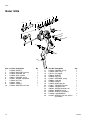
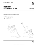
Instructions-Parts List
Pistol Grip Flow Gun
For dispensing ambient temperature sealants and adhesives.
Important Safety Instructions
Read all warnings and instructions in this manual.
Save these instructions.
See page 2 for part numbers and maxumum working pressure.
Models 12004 and 12005
Model 12004X
Model 12006
309739D
Models
Models
Pistol Grip, Base Seal
Part Number
Model
Pistol Grip, Tip Seal
Description
2500 psi (17.2 MPa, 172 bar) maximum working pressure
C27020
12004
Standard base seal
C27031
12004X
Two stage, easy pull
C27067
12005
Balanced piston
Part Number
Model
Description
2000 psi (13.79 MPa, 137.9 bar) maximum working pressure
C27078
12006
Pistol Grip, Tip Seal
Contents
Models . . . . . . . . . . . . . . . . . . . . . . . . . . . . . . . . . . . 2
Warnings . . . . . . . . . . . . . . . . . . . . . . . . . . . . . . . . . 3
Grounding and Electrical Requirements . . . . . . . . 4
Installation . . . . . . . . . . . . . . . . . . . . . . . . . . . . . . . . 5
Pressure Relief Procedure . . . . . . . . . . . . . . . . . 5
Trigger Lock . . . . . . . . . . . . . . . . . . . . . . . . . . . . . 5
Troubleshooting . . . . . . . . . . . . . . . . . . . . . . . . . . . . 6
Service . . . . . . . . . . . . . . . . . . . . . . . . . . . . . . . . . . . 8
Models 12004, 12004X . . . . . . . . . . . . . . . . . . . . 8
Model 12005 . . . . . . . . . . . . . . . . . . . . . . . . . . . . 9
Model 12006 . . . . . . . . . . . . . . . . . . . . . . . . . . . 11
Parts . . . . . . . . . . . . . . . . . . . . . . . . . . . . . . . . . . . . 12
Models 12004 & 12004X . . . . . . . . . . . . . . . . . . 12
Model 12005 . . . . . . . . . . . . . . . . . . . . . . . . . . . 13
Model 12006 . . . . . . . . . . . . . . . . . . . . . . . . . . . 14
Technical Data . . . . . . . . . . . . . . . . . . . . . . . . . . . . 15
Graco Standard Warranty . . . . . . . . . . . . . . . . . . . 16
Graco Information . . . . . . . . . . . . . . . . . . . . . . . . . 16
2
309739
Warnings
Warnings
Warning
ELECTRIC SHOCK HAZARD
Improper grounding, setup, or usage of the system can cause electric shock.
• Turn off and disconnect power at main switch before disconnecting any cables and before servicing
equipment.
•
All electrical wiring must be done by a qualified electrician and comply with all local codes and regulations.
•
Connect only to grounded power source.
SKIN INJECTION HAZARD
High pressure fluid from gun, hose leaks, or ruptured components will pierce skin. This may look like just
a cut, but it is a serious injury that can result in amputation. Get immediate surgical treatment.
• Do not point gun at anyone or at any part of the body.
•
Do not put your hand over the spray tip.
•
Do not stop or deflect leaks with your hand, body, glove, or rag.
•
Engage trigger lock when not spraying.
•
Follow Pressure Relief Procedure on page 5 if the nozzle clogs and before cleaning, checking or
servicing equipment.
TOXIC FLUID HAZARD
Toxic fluids or fumes can cause serious injury or death if splashed in the eyes or on the skin, inhaled, or
swallowed.
• Read MSDS’s to know the specific hazards of the fluids you are using.
•
Store hazardous fluid in approved containers and dispose of it according to applicable guidelines.
EQUIPMENT MISUSE HAZARD
Equipment misuse can cause death or serious injury.
• Do not exceed maximum working pressure or temperature rating of lowest rated system component.
See Technical Data in all equipment manuals.
309739
•
Use fluids and solvents that are compatible with equipment wetted parts. See Technical Data in all
equipment manuals. Read fluid and solvent manufacturers warnings.
•
Check equipment daily. Repair or replace worn or damaged parts immediately.
•
Do not alter or modify equipment.
•
For professional use only.
•
Use equipment only for its intended purpose. Call your Graco distributor for information.
•
Route hoses away from traffic areas, sharp edges, moving parts and hot surfaces.
•
Do not use hoses to pull equipment.
3
Grounding and Electrical Requirements
Grounding and Electrical Requirements
1. Pump: connect a ground wire and clamp to a true
earth ground as shown in pump manual.
2. Applicator: ground through motor cable assembly.
The following are minimum requirements for a basic dispensing system. Your system may include other equipment or objects that must be grounded. Check your local
electrical code for detailed grounding instructions for
your area and type of equipment.
To maintain grounding continuity when flushing or relieving pressure, always hold a metal part of spray gun
firmly to side of a grounded metal pail. Then trigger
spray gun.
3. Fluid and air hoses: only use electrically conductive material and air hoses.
4. Dispense gun: ground through connection of hose
or cable.
5. Air compressor: follow manufacturer’s recommendations.
6. Object being sprayed: refer to local code.
7. Fluid supply container: refer to local code.
8. Solvent pails used for flushing: refer to local
code.
ti3795a
4
309739
Installation
Installation
Inspect flow gun for shipping damage. If damage is
found notify the carrier immediately.
If material hose will be suspended by a hanger or
tool balancer, route hose through the suspension
device before securing each end of material hose.
1. Connect flow gun to any standard Graco hose
assembly.
2. Connect the opposite end of the heated hose
assembly to any fluid supply system. See Model
table, page 2 for maximum fluid working pressure
for your gun model.
3. Tighten fluid connections.
4. Before operating gun, squeeze and release trigger a
few cycles. Observe action of cartridge assembly.
Pressure Relief Procedure
If you suspect the tip/nozzle or hose is completely
clogged or that pressure has not been fully relieved after
following the above steps, VERY SLOWLY loosen the
retaining nut or hose end coupling to relieve pressure
gradually. Then loosen it completely. Clear tip/nozzle or
hose.
Trigger Lock
Always engage trigger lock when you stop dispensing to
prevent gun from being triggered accidentally by hand or
if dropped or bumped.
To engage trigger lock, release trigger and rotate lock
downward. See Fig. 1.
Do not try to force trigger valve open with trigger
lock engaged. This could result in component failure.
To help prevent injuries, follow this procedure
when you shut off the flow gun and before checking or adjusting any part of gun.
Trigger Lock
Engaged
FIG. 1: Trigger Lock Engaged
1. Shut off air to pump.
2. Close bleed-type master air valve (required in your
system).
To disengage trigger lock, rotate it upward. See Fig. 2.
3. Hold metal part of spray gun firmly to side of
grounded metal pail. Trigger gun to relieve pressure.
Trigger Lock
Disengaged
ti3795a
FIG. 2: Trigger Lock Disengaged
4. Open drain valve and/or pump bleeder valve having
a container ready to catch the drainage.
5. Leave drain valve open until you are ready to
spray/dispense again.
309739
5
Troubleshooting
Troubleshooting
Problem
Cause
Gun fails to dispense when trigger is Material lodged in nozzle
actuated
Material supply, hose, passages,
clogged
Solution
Follow Pressure Relief Procedure,
page 5. Clear nozzle of blockage.
Check material supply settings,
hoses, etc. for proper material supply.
Verify integrity of trigger pin through
yoke. Repair or replace cartridge
assembly as necessary.
Gun fails to dispense when trigger is Tension of trigger needs adjustment
engaged
Check spring tension adjustment at
rear of gun. Spring tension should be
adjusted to allow approximately 1/32
in. of free play on trigger.
Verify integrity of trigger pin through
yoke. Repair or replace cartridge
assembly as necessary.
Needle and seat adapter loose or
worn
Check that seat adapter is tightened
firmly and flush to gun body.
Needle and seat adapter worn.
Replace components as necessary.
Seal leakage
Material leaks from gun inlet swivel
6
Packing adjustment nut not snug
Follow Pressure Relief Procedure,
page 5. Tighten packing adjustment
nut.
Worn seals and packings
Rebuild gun as necessary.
Worn seals
Replace seals.
309739
Troubleshooting
309739
7
Service
Service
Models 12004, 12004X
Reassembly
Disassembly
1. Actuate gun to purge material and relieve pressure
in gun. Pressure Relief Procedure, page 5.
2. Disconnect material supply line from gun handle.
3. Hold adapter (9) stationary and unscrew nozzle and
collar (16).
4. With trigger depressed, unscrew adapter (9) from
gun body (17).
Clean all parts thoroughly before reassembling. Check
them carefully for damage or wear, replacing parts as
needed. For best results replace the original parts with
new parts in repair kits.
Prior to assembly, lubricate all seals and o-rings with
PARKER-O-LUBE or an equivalent lubricant.
1. Push seals (6) in the packing nut (5).
2. Screw adjusting screw (3) into packing nut (5).
Insert needle/ball (8) into packing support (7).
5. Remove o-ring (10) from adapter (9).
6. Loosen lock nut (14).
Nut
7. Carefully unscrew and remove spring retainer (15)
and spring (13) from the gun body (17).
8. Remove screw (11) and lock washer (23) from side
of trigger (18).
Packing Nut
Packing Support
Needle/ball
Yoke
9. Pull trigger pins (12) from gun body (17) and remove
trigger (18).
Adjusting Screw
10. Unscrew packing nut (5) from gun body (17).
Seal
ti3810a
11. Remove cartridge assembly through side of gun
handle.
Cartridge Disassembly Procedure
O-Ring
3. Attach needle/ball (8) to yoke (1) using slot in the
yoke to screw needle/ball.
1. Remove o-ring (4) from groove on packing nut (5).
4. Secure yoke in soft jawed vice. Tighten lock nut to
cartridge.
2. Loosen lock nut (14) on cartridge while holding yoke
(1) in a soft
5. Install o-ring (4) onto groove in packing nut (5).
3. Separate needle/ball (8) from yoke (1) using the slot
in needle/ball to unscrew the yoke.
4. Remove adjusting screw (3) from packing nut (5).
Then, separate needle/ball (8) from packing support
(7).
5. Push seals (6) out of packing nut (5).
6. Insert cartridge assembly through front of gun handle.
7. Screw packing nut (5) in gun body (17).
8. Install trigger (18) and insert trigger pins (12) in gun
body (17). Secure using screws (11) and lock washers (23).
9. Install snap rings (11) from top to bottom to secure
trigger pins (12).
Nut
10. Install spring (13) and spring retainer (15) into the
gun body (17). Adjust spring retainer to allow
approximately 1/32 in. of free play on trigger.
Packing Nut
Packing Support
Needle/ball
11. Tighten lock nut (14).
Yoke
12. Install o-ring (10) to adapter (9).
13. With trigger retracted, screw adapter (9) into gun
body (17).
Adjusting Screw
Seal
ti3810a
O-Ring
8
309739
Service
14. Hold adapter (9) stationary and screw nozzle and
collar (16) into adapter. Do not over tighten collar.
Cartridge Disassembly Procedure
1. Remove guide (22) from needle (8).
15. Reconnect flow gun to material supply line.
16. Turn on material supply line.
17. Return flow gun to normal operating condition.
Model 12005
ti4035a
2. Remove two o-rings (23) from guide (22).
Disassembly
1. Actuate gun to purge material and relieve pressure
in gun. Pressure Relief Procedure, page 5.
2. Disconnect material supply line from gun handle.
3. Hold adapter (9) stationary and unscrew nozzle and
collar (16).
4. With trigger depressed, unscrew adapter (9) from
gun body (17).
ti4036a
3. Unwind spiral PTFE o-ring backup (21) from
guide(22).
5. Remove o-ring (10) from adapter (9).
4. Loosen adjustment screw (3) while holding packing
nut (5).
6. Loosen lock nut (14).
5. Extract needle (8) from packing nut (5).
7. Carefully unscrew and remove spring retainer (15)
6. Remove o-ring (4) from groove in packing nut (5).
8. Remove screws (11) and lock washers (28) from
trigger pins (12).
7. Remove adjustment screw (3).
9. Pull trigger pins (12) from gun body (17) and remove
trigger (18).
8. Push three seal-needles (6) out of packing nut (5)
with soft rod or dowel.
10. Remove piston valve (20) from front of gun.
11. Unscrew packing nut (5) from gun body (17).
12. Remove cartridge assembly from gun.
ti4039a
9. Hold yoke (1) in soft-jawed vice. Unlock stop nut (2).
ti4040a
10. Separate needle (8) from yoke (1).
309739
9
Service
Reassembly
12. Tighten nut (19) on needle (8).
Clean all parts thoroughly before reassembling. Check
them carefully for damage or wear, replacing parts as
needed. For best results replace the original parts with
new parts in repair kits.
Prior to assembly, lubricate all seals and o-rings with
PARKER-O-LUBE or an equivalent lubricant.
1. Connect needle (8) and stop nut (2) to yoke (1).
2. Secure yoke (1) in soft jawed vise. Lock stop nut (2)
against yoke.
ti4051a
13. Adjust screw (3) to tighten packings.
14. Install trigger (18). Align yoke (1) in gun body (17).
15. Press trigger pin (12) into gun body.
16. Secure trigger pins (12) using screws (11) and lock
washers (28).
17. Install spring (13) and spring retainer (15) into gun
body (17).
18. Adjust spring retainer to allow approximately 1/32 in.
of free play on trigger.
ti4043a
3. Insert needle (8) into packing nut (5).
4. Push three seal needles (6) in packing nut (5) using
soft rod or dowel. Orient as shown below
19. Tighten stop nut (14).
20. Install o-ring (10) on adapter (9).
21. With trigger retracted screw adapter (9) on gun body
(17).
22. While holding adapter (9) stationary, screw collar
(16) and nozzle into adapter. Do not over tighten
collar.
23. Reconnect flow gun to material supply line.
ti4045a
5. Install o-ring (4) on groove of packing nut (5).
24. Turn on material supply line to gun.
6. Install guide (22) on needle (8).
25. Return flow gun to normal operating condition.
7. Rewind spiral o-ring backup (21) on guide (22).
8. Install two o-rings (23) on guide (22).
9. Insert cartridge assembly in gun body (17) from rear
of gun.
10. Screw packing nut (5) into gun body (17).
11. Insert valve (20) through front of gun on needle (8).
ti4050a
10
309739
Service
Model 12006
Reassembly
Disassembly
Clean all parts thoroughly before reassembling. Check
them carefully for damage or wear. Replace parts as
needed. For best results replace the original parts with
new parts in repair kits.
1. With trigger (20) depressed, remove collar (17)
securing nozzle (18) to gun.
2. Remove nozzle (18), holding adapter (10) firmly to
prevent it from turning.
Prior to assembly, lubricate all seals and o-rings with
PARKER-O-LUBE or an equivalent lubricant.
3. Remove gasket (9). Clean and inspect for damage.
1. Replace o-ring (5) and seals (4) in packing nut (6).
4. Remove adapter (10) from gun body.
Nut
5. Remove both screws (12) and lock washers (25) on
one side of trigger (20) and push both trigger pins
(13) out of body.
6. Loosen lock nut (15) at rear of gun.
Packing Nut
Packing Support
Needle
7. Unthread spring retainer (16) and remove spring
(14).
Yoke
8. Loosen and remove adjustment screw (6) on packing nut (3) and pull needle assembly from rear of
gun. Inspect for damage, replace if needed.
Adjusting Screw
Seal
O-Ring
9. Remove packing assembly from gun.
10. Unthread packing nut (3) from body.
11. Remove adjustment screw (6) and o-ring (5) and
seals (4).
ti4057a
2. Thread packing nut (3) into gun body.
3. Install packing assembly through rear of gun.
4. Install needle assembly through rear of gun.
5. Install spring (14) and spring retainer (16) into gun
body. Adjust spring retainer to allow approximately
1/32 in. of free play on trigger.
6. Tighten lock nut (15).
7. Install trigger (20) and insert trigger pins (13) in gun
body.
8. Secure trigger pins (13) using screws (12) and lock
washers (25).
9. Replace o-ring (11). Lubricate with petroleum jelly to
aid in reassembly.
10. With trigger (20) retracted, screw adapter (10) into
gun body.
11. Insert gasket (9) in collar (17).
12. While holding adapter stationary, screw collar (17)
and nozzle (18) into adapter. Do not overtighten collar.
13. Reconnect flow gun to material supply line.
14. Turn on material supply line.
15. Return flow gun to normal operating condition.
309739
11
Parts
Parts
Models 12004 & 12004X
13
1
2
5
4
7
3
6
14
15
10
9
21
19
16
20
12
17
8
11
23
18
Item Part No.
1
C27052
2
100284
C19284
3
C27061
4
106555
5
C27058
6
C27060
7
C27053
8
C27038
9
C27063
10
C20102
11
C19950
12
12
Description
Qty
YOKE
1
NUT, hex (model 12004)
1
NUT, hex (model 12004-X)
1
SCREW, adjustment
1
PACKING, o-ring
1
PACKING, nut
1
SEAL, needle
3
SUPPORT, packing
1
NEEDLE
1
ADAPTER, ball seat
1
PACKING, o-ring
1
SCREW, cap, sch
(model 12004) 2
(model 12004-X) 3
15X116 PIN, trigger (model 12004)
2
(model 12004-X) 3
Item
13
14
15
16
17
18
19
20
21
22
23
24
Part No.
C00020
C27036
C27037
C00004
C27049
C27051
C34009
108483
C20565
070269
C19208
Description
Qty
SPRING
1
NUT, lock
1
RETAINER, spring
1
COLLAR
1
BODY, flow gun
1
TRIGGER, hot melt
1
TRIGGER, lock
1
SCREW, shoulder, sch
1
WASHER, spring
1
SEALANT, anaerobic
LOCKWASHER
(model 12004) 2
(model 12004-X) 3
101369 WRENCH, hex key, 3/32 in.
1
(not shown)
309739
Parts
Model 12005
13
1
3
10
9
2
5
4
16
6
14
15
27
24
25
22
21
19
23
12
17
20
8
28
11
18
Item
1
2
3
4
5
6
8
9
10
11
12
13
14
15
309739
Part No.
C27052
C19284
C27061
106555
C27058
C27060
C27071
C27077
C20102
C19950
15X116
C00020
C27036
C27037
Description
YOKE
NUT, hex
SCREW, adjustment
PACKING, o-ring
PACKING, nut
SEAL, needle
NEEDLE
FITTING, adapter
PACKING, o-ring
RING, snap
PIN, trigger
SPRING
NUT, lock
RETAINER, spring
Qty
1
1
1
1
1
3
1
1
1
2
2
1
1
1
Item
16
17
18
19
20
21
22
23
24
25
26
27
28
29
Part No.
C00004
C27049
C27051
C27076
C27072
C27074
C27075
103337
C34009
108483
C20565
070269
C19208
101369
Description
COLLAR
BODY, flow gun
TRIGGER, hot melt
NUT
VALVE, piston
PACKING, PTFE o-ring
GUIDE
PACKING, o-ring
TRIGGER, lock
SCREW, shoulder, sch
WASHER, spring
SEALANT, anaerobic
LOCKWASHER
WRENCH, hex key, 3/32 in.
(not shown)
Qty
1
1
1
1
1
1
1
2
1
1
1
2
1
13
Parts
Model 12006
8
3
18
9
16
5
2
6
14
7
4
15
16
24
21
22
11
10
1
13
12
25
20
Item
1
2
3
4
5
6
7
8
9
10
14
Part No.
C27080
C27053
C27058
C27060
106555
C27061
C19284
C27052
C02064
C27063
Description
NEEDLE
SUPPORT, packing
PACKING, nut
SEAL, needle
PACKING, o-ring
SCREW, adjustment
NUT, hex
YOKE
GASKET
ADAPTER, ball seat
Qty
1
1
1
3
1
1
1
1
1
1
Item
11
12
13
14
15
16
17
18
19
20
21
22
23
24
25
26
Part No.
C20102
C19950
15X116
C00020
C27036
C27037
C00004
C27086
C27049
C27051
C34009
108483
C20565
070269
C19208
101369
Description
PACKING, o-ring
RING, snap
PIN, trigger
SPRING
NUT, lock
RETAINER, spring
COLLAR
NOZZLE
BODY, flow gun
TRIGGER, hot melt
TRIGGER, lock
SCREW, shoulder, sch
WASHER, spring
SEALANT, anaerobic
LOCKWASHER
WRENCH, hex key, 3/32 in.
(not shown)
Qty
1
2
2
1
1
1
1
1
1
1
1
1
1
2
1
309739
Technical Data
Technical Data
Maximum fluid working pressure . . . . . . . . . . . . . . . . . . . Models 12004X, 12004, and 12005: 2500 psi (17.2 MPa,
172 bar)
Model 12006: 2000 psi (13.79 MPa, 137.9 bar)
Inlet port size on gun housing . . . . . . . . . . . . . . . . . . . . . 1/2-14 NPT
Weight . . . . . . . . . . . . . . . . . . . . . . . . . . . . . . . . . . . . . . . Models 12004X, 12004, and 12005: 1.4 lb (.64 kg)
Model 12006: 1.6 lb (.73 kg)
Dimensions. . . . . . . . . . . . . . . . . . . . . . . . . . . . . . . . . . . . Height: 7 in. (178 mm)
Width: 2 in. (51 mm)
Length:
Models 12004X, 12004, and 12005: 7 in. (178 mm)
Model 12006: 9 in. (229 mm)
Wetted parts . . . . . . . . . . . . . . . . . . . . . . . . . . . . . . . . . . . Models 12004 and 12004X: aluminum, fluorocarbon
rubber, carbon steel, tool steel, brass, tetrafluoroethylene
Model 12005: aluminum, fluorocarbon rubber, carbon
steel, brass, fluoroelastomer, stainless steel, PTFE,
tetrafluoroethylene
Model 12006: aluminum, fluorocarbon rubber, carbon
steel, brass, tetrafluoroethylene
CE Approval . . . . . . . . . . . . . . . . . . . . . . . . . . . . . . . . . . . Models 12004X, 12004, and 12005: Yes
Model 12006: No
309739
15
Graco Standard Warranty
Graco warrants all equipment referenced in this document which is manufactured by Graco and bearing its name to be free from defects in
material and workmanship on the date of sale to the original purchaser for use. With the exception of any special, extended, or limited warranty
published by Graco, Graco will, for a period of twelve months from the date of sale, repair or replace any part of the equipment determined by
Graco to be defective. This warranty applies only when the equipment is installed, operated and maintained in accordance with Graco’s written
recommendations.
This warranty does not cover, and Graco shall not be liable for general wear and tear, or any malfunction, damage or wear caused by faulty
installation, misapplication, abrasion, corrosion, inadequate or improper maintenance, negligence, accident, tampering, or substitution of
non-Graco component parts. Nor shall Graco be liable for malfunction, damage or wear caused by the incompatibility of Graco equipment with
structures, accessories, equipment or materials not supplied by Graco, or the improper design, manufacture, installation, operation or
maintenance of structures, accessories, equipment or materials not supplied by Graco.
This warranty is conditioned upon the prepaid return of the equipment claimed to be defective to an authorized Graco distributor for verification of
the claimed defect. If the claimed defect is verified, Graco will repair or replace free of charge any defective parts. The equipment will be returned
to the original purchaser transportation prepaid. If inspection of the equipment does not disclose any defect in material or workmanship, repairs will
be made at a reasonable charge, which charges may include the costs of parts, labor, and transportation.
THIS WARRANTY IS EXCLUSIVE, AND IS IN LIEU OF ANY OTHER WARRANTIES, EXPRESS OR IMPLIED, INCLUDING BUT NOT LIMITED
TO WARRANTY OF MERCHANTABILITY OR WARRANTY OF FITNESS FOR A PARTICULAR PURPOSE.
Graco’s sole obligation and buyer’s sole remedy for any breach of warranty shall be as set forth above. The buyer agrees that no other remedy
(including, but not limited to, incidental or consequential damages for lost profits, lost sales, injury to person or property, or any other incidental or
consequential loss) shall be available. Any action for breach of warranty must be brought within two (2) years of the date of sale.
GRACO MAKES NO WARRANTY, AND DISCLAIMS ALL IMPLIED WARRANTIES OF MERCHANTABILITY AND FITNESS FOR A
PARTICULAR PURPOSE, IN CONNECTION WITH ACCESSORIES, EQUIPMENT, MATERIALS OR COMPONENTS SOLD BUT NOT
MANUFACTURED BY GRACO. These items sold, but not manufactured by Graco (such as electric motors, switches, hose, etc.), are subject to
the warranty, if any, of their manufacturer. Graco will provide purchaser with reasonable assistance in making any claim for breach of these
warranties.
In no event will Graco be liable for indirect, incidental, special or consequential damages resulting from Graco supplying equipment hereunder, or
the furnishing, performance, or use of any products or other goods sold hereto, whether due to a breach of contract, breach of warranty, the
negligence of Graco, or otherwise.
FOR GRACO CANADA CUSTOMERS
The Parties acknowledge that they have required that the present document, as well as all documents, notices and legal proceedings entered into,
given or instituted pursuant hereto or relating directly or indirectly hereto, be drawn up in English. Les parties reconnaissent avoir convenu que la
rédaction du présente document sera en Anglais, ainsi que tous documents, avis et procédures judiciaires exécutés, donnés ou intentés, à la suite
de ou en rapport, directement ou indirectement, avec les procédures concernées.
Graco Information
TO PLACE AN ORDER, contact your Graco distributor or call to identify the nearest distributor.
Phone: 612-623-6921 or Toll Free: 1-800-328-0211, Fax: 612-378-3505
All written and visual data contained in this document reflects the latest product information available at the time of publication.
Graco reserves the right to make changes at any time without notice.
This manual contains English. MM 309739
Graco Headquarters: Minneapolis
International Offices: Belgium, China, Japan, Korea
GRACO INC. P.O. BOX 1441 MINNEAPOLIS, MN 55440-1441
Copyright 2002, Graco Inc. is registered to ISO 9001
www.graco.com
Revised 1/2009