1
INSTRUCTIONS-PARTS LIST
308–293
Rev. G
Supersedes E
and PCN G
This manual contains important
warnings and information.
READ AND KEEP FOR REFERENCE.
INSTRUCTIONS
Model M-1265, Series B
Optimiser
HVLP Spray Gun
100 psi (0.7 MPa, 7 bar) Maximum Working Fluid Pressure
100 psi (0.7 MPa, 7 bar) Maximum Working Air Pressure
65 psi (444 kPa, 4.4 bar) Maximum Compliant Inbound Air Pressure
U.S. Patent Pending
GRACO INC.
P.O. BOX 1441 MINNEAPOLIS, MN
COPYRIGHT 1993, GRACO INC.
Graco Inc. is registered to I.S. EN ISO 9001
55440–1441
Table of Contents
Warnings . . . . . . . . . . . . . . . . . . . . . . . . . . . . . . . . . . . . . . 2
Selection Charts . . . . . . . . . . . . . . . . . . . . . . . . . . . . . . . 4
Air Flow and Atomizing Pressure . . . . . . . . . . . . . . . . . 7
Typical Installation . . . . . . . . . . . . . . . . . . . . . . . . . . . . . . 8
Setup . . . . . . . . . . . . . . . . . . . . . . . . . . . . . . . . . . . . . . . . . 9
Operation . . . . . . . . . . . . . . . . . . . . . . . . . . . . . . . . . . . . 13
Daily Gun Care, Flushing, and Cleaning . . . . . . . . . . 14
Troubleshooting . . . . . . . . . . . . . . . . . . . . . . . . . . . . . . . 18
Service . . . . . . . . . . . . . . . . . . . . . . . . . . . . . . . . . . . . . . 20
Part Drawing . . . . . . . . . . . . . . . . . . . . . . . . . . . . . . . . . 24
Parts List . . . . . . . . . . . . . . . . . . . . . . . . . . . . . . . . . . . . . 25
Accessories . . . . . . . . . . . . . . . . . . . . . . . . . . . . . . . . . . 26
Technical Data . . . . . . . . . . . . . . . . . . . . . . . . . . . . . . . . 28
Dimensions . . . . . . . . . . . . . . . . . . . . . . . . . . . . . . . . . . . 28
Warranty . . . . . . . . . . . . . . . . . . . . . . . . . . . . . . . . . . . . . 32
Symbols
Warning Symbol
WARNING
This symbol alerts you to the possibility of serious
injury or death if you do not follow the instructions.
Caution Symbol
CAUTION
This symbol alerts you to the possibility of damage to
or destruction of equipment if you do not follow the
instructions.
WARNING
EQUIPMENT MISUSE HAZARD
INSTRUCTIONS
Equipment misuse can cause the equipment to rupture, malfunction or start unexpectedly and result in
serious injury.
D This equipment is for professional use only.
D Read all instruction manuals, tags, and labels before operating the equipment.
D Use the equipment only for its intended purpose. If you are uncertain about usage, call your Graco
distributor.
D Do not alter or modify this equipment. Use only genuine Graco parts and accessories.
D Check equipment daily. Repair or replace worn or damaged parts immediately.
D Use this equipment only in low pressure, air spray systems.
D Do not exceed the maximum working pressure of the lowest rated system component. This equipment has a 100 psi (0.7 MPa, 7 bar) maximum working fluid and air pressure.
D Route the hoses away from the traffic areas, sharp edges, moving parts, and hot surfaces. Do not
expose Graco hoses to temperatures above 180_F (82_C) or below –40_F (–40_C).
D Wear hearing protection when operating this equipment.
D Use fluids or solvents that are compatible with equipment wetted parts. See the Technical Data
section of all equipment manuals. Read the fluid and solvent manufacturer’s warnings.
D Methylene Chloride with formic or propionic acid is not recommended as a flushing or cleaning
solvent with this gun or any other device with nylon or aluminum components as it can damage
these parts.
D Comply with all applicable local, state and national fire, electrical and other safety regulations.
2
308–293
WARNING
PRESSURIZED EQUIPMENT HAZARD
Spray from the gun, hose leaks or ruptured components can splash fluid in the eyes or on the skin and
cause serious injury.
Do not stop or deflect fluid leaks with your hand, body, glove or rag.
Follow the Pressure Relief Procedure on page 13 when: you are instructed to relieve pressure;
stop spraying; clean, check or servicing the equipment; and install or clean fluid nozzles.
Do not point the spray gun at anyone or at any part of the body.
Tighten all fluid connections before operating the equipment.
Check the hoses, tubes and couplings daily. Replace worn, damaged or loose parts immediately.
Permanently coupled hoses cannot be repaired; replace the entire hose.
FIRE AND EXPLOSION HAZARD
Poor air ventilation, open flames, or sparks can cause a hazardous condition and result in fire or
explosion and serious injury.
Provide fresh air ventilation to avoid the buildup of flammable fumes from solvent or the fluid being
sprayed.
Extinguish all open flames or pilot lights in the spray area.
Electrically disconnect all equipment in the spray area.
Keep the spray area free of debris, including solvent, rags and gasoline.
Do not turn on or off any light switch in the spray area while operating or if fumes are present.
Do not smoke in the spray area.
Do not operate a gasoline engine in the spray area.
TOXIC FLUID HAZARD
Hazardous fluids or toxic fumes can cause serious injury or death if splashed in the eyes or on the
skin, inhaled, or swallowed.
Know the specific hazards of the fluid you are using. Read the fluid manufacturer’s warnings.
Store hazardous fluid in an approved container. Dispose of hazardous fluid according to all local,
state and national guidelines.
Dress appropriately for your application. Wear the appropriate protective clothing, gloves, eyewear,
and respirator.
308–293
3
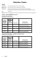
Selection Charts
TERMS:
Light Fluid:
Up to 18 seconds with No. 2 Zahn cup (20 centipoise)
Medium Fluid:
19 to 28 seconds with No. 2 Zahn cup (20–64 centipoise)
Heavy Fluid:
Greater than 28 seconds with No. 2 Zahn cup (greater than 64 centipoise) -2.8 Volatile Organic Compounds, High-solid Polyurethanes, Heavy Waterborne Enamels
P/N:
Part number
NOTE: See page 6 for additional tips on selecting the needle/nozzle/air cap set best suited to your application.
CHART 1: GUN ASSEMBLIES, Series B
Standard Gun Assemblies
With standard needle/nozzle/air cap kit
Includes:
Standard
Complete
Gun Assy.
Part No.
Standard
Needle/
Nozzle/Air
Cap Kit P/N
Orifice Size
236–013
238–233
0.042” (1.067 mm)
Light to Medium Fluids or Low Fluid Flow
[5–8 oz./min. (0.15–0.24 l/min.)]
236–014
238–234
0.055” (1.397 mm)
Light to Medium Fluids or Medium Fluid
Flow [6–12 oz./min. (0.18–0.36 l/min.)]
236–015
238–235
0.070” (1.778 mm)
Medium to Heavy Fluids or Medium Fluid
Flow [6–12 oz./min. (0.18–0.36 l/min.)]
236–016
238–236
0.086” (2.184 mm)
Heavy Fluids or High Fluid Flow
[10–15 oz./min. (0.3–0.45 l/min.)]
Material Usage
(See TERMS above)
Optional Gun Assemblies – available as “Build to Order”
With optional needle/nozzle/air cap kit
Includes:
4
Optional
Complete
Gun Assy.
Part No.
Optional
Needle/
Nozzle/Air
Cap Kit P/N
Orifice Size
236–020
238–230
0.020” (0.508 mm)
Light Fluids or Low Fluid Flow
[3–6 oz./min. (0.09–0.18 l/min.)]
236–021
238–231
0.026” (0.660 mm)
Light Fluids or Low Fluid Flow
[3–6 oz./min. (0.09–0.18 l/min.)]
236–022
238–232
0.030” (0.762 mm)
Light to Medium Fluids or Low Fluid Flow
[5–8 oz./min. (0.15–0.24 l/min.)]
308–293
Material Usage
(See TERMS above)
Selection Charts
CHART 1: GUN ASSEMBLIES, Series B (continued)
Optional Non-HVLP Compliant Gun Assemblies
With standard needle and nozzle and optional high pressure air cap
Includes:
Optional
Complete
Gun Assy.
Part No.
Needle
Assy.
P/N
*
Nozzle
P/N
{ High
Pressure
Air Cap
P/N
Orifice Size
236–023
238–217
276–293
189–755
0.042” (1.067 mm)
Light to Medium Fluids or Low Fluid Flow
[5–8 oz./min. (0.15–0.24 l/min.)]
236–024
238–218
276–294
189–755
0.055” (1.397 mm)
Light to Medium Fluids or Medium Fluid
Flow [6–12 oz./min. (0.18–0.36 l/min.)]
Material Usage
(See TERMS on page 4)
*
Maximum recommended torque to install molded fluid nozzle in the spray gun is 35 in-lbs (4 NSm).
{
See atomizing air pressure chart on page 7.
CHART 2: NEEDLE/NOZZLE/AIR CAP KITS
Standard Needle/Nozzle/Air Cap Kits
Includes:
Standard
Needle/
Nozzle/Air
Cap Kit
Part No.
{
{ Needle
Assy.
P/N
*
Nozzle
P/N
Air Cap
P/N
Orifice Size
238–233
238–217
276–293
188–754
0.042” (1.067 mm)
238–234
238–218
276–294
188–754
0.055” (1.397 mm)
238–235
238–219
276–295
188–755
0.070” (1.778 mm)
238–236
238–220
276–296
188–756
0.086” (2.184 mm)
See page 6 for needle assembly replacement tips.
Optional Needle/Nozzle/Air Cap Kits – available as “Build to Order”
Optional
Needle/
Nozzle/Air
Cap Kit
Part No.
Includes:
{ Needle
Assy.
P/N
*
Nozzle
P/N
Air Cap
P/N
Orifice Size
235–306
238–703
276–290
188–754
0.020” (0.508 mm)
235–307
238–703
276–291
188–754
0.026” (0.660 mm)
235–308
238–703
276–292
188–754
0.030” (0.762 mm)
*
Maximum recommended torque to install molded fluid nozzle in the spray gun is 35 in-lbs (4 NSm).
{
See page 6 for needle assembly replacement tips.
308–293
5
Selection Charts
CHART 3: OPTIONAL ORIFICE PURGE
SST NEEDLE Optional
Stainless Steel
Orifice-Purge
Needle Part No.
Orifice Size
186–931
0.042” (1.067 mm)
186–932
0.055” (1.397 mm)
186–933
0.070” (1.778 mm)
186–934
0.086” (2.184 mm)
CHART 4: NEEDLE ASSEMBLY
REPLACEMENT TIPS
Needle Assembly
Part No.
Needle Tip P/N
238–217
191–016
238–218
191–017
238–219
191–018
238–703
191–564
Use these needles to purge fluid out of the nozzle
orifice to prevent plugging of the tip with fast drying
material. A needle shaft assembly (part no.
224–849) must be used with these needles and
replaces the standard one-piece needles.
Selecting the Proper Needle/Nozzle/Air
Cap Set
The High Volume Low Pressure Spray Gun’s needle/
nozzle sets range in size to provide different fluid flow
rates. Chart 1 shows the recommended combinations
based on fluid viscosities and flow rates.
As a general guideline, use the fluid nozzle that will
give the required flow with the needle fully triggered at
the lowest fluid pressure.
For low flow rates or light viscosity fluid, select the
smaller nozzle sizes.
For high flow rates or high viscosity fluid, select the
larger nozzle sizes.
Using an air cap size that is smaller than the nozzle/
needle size is not recommended.
NOTE: To help select the proper needle/nozzle size, a
fluid pressure gauge may be connected temporarily to
the gun fluid inlet to determine the fluid pressure. See
Accessories.
6
308–293
Selection Problems and Solutions
PROBLEM
POSSIBLE
CAUSE
SOLUTION
Fluid pressure is too
high (greater than
10 psi [70 kPa, 0.7
bar]) with gun triggered
Using set with
too small orifice
Use needle/
nozzle/air cap
set with larger
orifice
Using a low pressure setting, the
fluid flow is too high,
making it necessary
to restrict needle
travel to reduce fluid
flow.
Using set with
too large orifice
Use needle/
nozzle/air cap
set with smaller orifice
Fluid system will not
operate at low
enough fluid pressure [below 10 psi
(70 kPa, 0.7 bar)]
There’s no fluid
regulator or air
regulator is not
sensitive
enough
Add low pressure fluid regulator or add
more sensitive
air regulator on
pressure pot
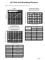
Air Flow and Atomizing Pressure
NOTE: All tests were completed with the pattern adjustment valve fully open.
Models 236–023 & 236–024
All other models
Atomizing Air Pressure
(inlet pressure versus atomizing pressure)
Models 236–023 and 236–024
"# #!
Air Flow
Model 236–023
Model 236–024
"# "# NOMINAL ATOMIZING PRESSURE (psi)
Atomizing Air Pressure
(inlet pressure versus atomizing pressure)
Gun Inlet
Pressure
(kPa bar)
psi (kPa,
Models 236–013 to 236–016 and
236–020 to 236–028
Model 236–023
Model 236–024
20 (140, 1.4)
6 (41, 0.4)
7 (48, 0.4)
30 (210, 2.1)
10 (70, 0.7)
12 (84, 0.8)
40 (280, 2.8)
16 (111, 1.1)
18 (125, 1.2)
50 (345, 3.4)
21 (147, 1.5)
24 (168, 1.6)
60 (410, 4.1)
26 (181, 1.8)
30 (210, 2.1)
70 (480, 4.8)
32 (224, 2.2)
36 (251, 2.5)
80 (550, 5.5)
38 (265, 2.6)
42 (294, 2.9)
90 (620, 6.2)
43 (301, 3.0)
48 (335, 3.3)
100 (700, 7.0)
48 (335, 3.3)
54 (373, 3.7)
Nominal Atomizing Pressure
psi (kPa, bar)
GUN INLET PRESSURE (psi)
Gun Inlet Pressure
psi (kPa, bar)
Nominal Atomizing Pressure
psi (kPa, bar)
15 (104, 1.0)
1.5 (10.5, 0.1)
25 (174, 1.7)
3.0 (21.0, 0.2)
35 (244, 2.4)
4.5 (31.5, 0.3)
45 (312, 3.1)
6.0 (41.0, 0.4)
55 (379, 3.7)
8.5 (58.5, 0.6)
65 (444, 4.4)
10.0 (70.0, 0.7)
75 (514, 5.1)
13.0 (91.0, 0.9)
85 (584, 5.8)
15.5 (107.5, 1.1)
95 (654, 6.5)
18.0 (125.0, 1.2)
308–293
7
Typical Installation
NOTE: See the Accessories section for
accessories recommended to install the system.
E
F
G
H
A
B
C
KEY
A
B
C
D
E
F
G
H
Model M-1265 Spray Gun
See page 4 for part numbers.
Fluid Inlet; 3/8 npsm (R3/8–19)
Air Inlet; 1/4 npsm
Air Hose
Recommend 5/16” (7.9 mm) ID hose
Optional 3/8” (9.5 mm) ID hose
Air Shut-off Valve
Air Regulator
Air Filter
Air Supply Line
D
02018
The M-1265 HVLP Spray Gun
The Model M-1265 HVLP Spray Gun was designed to
produce the highest quality finish with today’s fluids as
well as the the Low V.O.C. (volatile organic compound)
fluids of tomorrow.
This spray gun can spray most coatings or finishes
currently being used for automotive refinish, industrial,
aerospace, marine, wood, plastic and architectural
applications, while easily operating from any paint
delivery system, including cups, pressure pots, or
remote pumps for production line operation.
The Model M-1265 HVLP Spray Gun typically utilizes
65 psi (444 kPa, 4.4 bar) inbound air pressure to
produce high quality paint finishes at 10 psi (0.07 bar)
atomizing air pressure.
The air regulator must have a minimum air flow
capacity of 30 scfm at 100 psi (0.7 MPa, 7 bar) air
pressure.
NOTE: If the gun’s hanging hook is needed, remove
the gun trigger and replace the gun plate with the
hook, then reinstall the trigger. See the parts drawing,
page 24.
8
308–293
Ventilate the Spray Booth
WARNING
To prevent hazardous concentrations of
toxic and/or flammable vapors, spray
only in a properly ventilated spray booth.
Do not operate the spray gun unless
ventilation fans are operating.
Check and follow all of the National,
State and Local codes regarding air exhaust velocity requirements.
Check and follow all local safety and fire codes.
Setup
1. Connect the Air Line
2. Connect the Fluid Hose
NOTE:
NOTE:
You must install an air pressure regulator (F) on the
gun air line to control air pressure to the gun. See
Fig. 2.
Before connecting the fluid line, blow it out with air
and flush it with solvent. Use solvent which is
compatible with the fluid to be sprayed.
If your regulated air source does not have a filter,
install an air filter (G) on the air line to ensure a dry,
clean air supply to the gun. Dirt and moisture can
ruin the appearance of your finished workpiece.
See Fig. 2.
Use a 5/16 inch (7.9 mm) I.D. air hose to minimize
excessive pressure drop in the hose.
Install a fluid regulator (L) on the fluid line to control
fluid pressure to the gun. See Fig. 4.
Filter the fluid line of coarse particles and sediment
to avoid clogging the fluid nozzle and causing
finishing defects.
A. Connect the fluid hose (J) to the gun fluid inlet (B)
3/8–18 npsm [R 3/8–19] compound thread.
A. Connect the air hose (D) to the 1/4 npsm gun air
inlet (C).
B
J
C
D
02052
Fig. 3
02051
Fig. 1
B. Connect the other end of the fluid hose (J) to a
regulated fluid supply line (K).
B. Connect the other end of the air hose (D) to a regulated air supply line (H).
NOTE: Fig. 4 shows the fluid regulator (L) and
fluid shut-off valve (M) on the fluid supply line (K).
NOTE: Fig. 2 shows the filter (G) air regulator (F),
and air shut-off valve (E) on the air supply line.
H
K
G
F
L
M
J
E
Fig. 2
D
01990
02054
Fig. 4
308–293
9
Setup
3. Flush the Spray Gun.
6. Adjust the Spray Pattern
Before running any paint through the spray gun, flush
the gun out with a solvent that is compatible with the
fluid to be sprayed, using the lowest possible fluid
pressure and a grounded metal container.
WARNING
COMPONENT RUPTURE HAZARD
Do not exceed the 100 psi (0.7 MPa,
7 bar) maximum fluid and air pressure of this gun. Higher pressures can cause parts
to rupture and result in serious injury.
Follow these steps to establish the correct fluid flow
and air flow:
A. Turn the fluid adjustment knob (8) counterclockwise until no restriction of the trigger movement is
felt, then turn the knob another half turn. When the
knob is turned far enough, the trigger should be
able to touch the gun handle when the gun is triggered.
02053
Fig. 5
WARNING
8
PRESSURIZED EQUIPMENT HAZARD
To reduce the risk of a serious injury whenever you
are instructed to relieve pressure, follow the Pressure Relief Procedure on page 13.
open
4. Relieve the Pressure.
5. Position the Air Cap
Rotate the air cap as needed to achieve the desired
spray pattern direction. To create a round pattern, turn
the pattern air off by turning the pattern adjustment
knob (13a) fully clockwise. Refer to Fig. 12.
Vertical Pattern
Horizontal Pattern
02020
Fig. 6
10
308–293
02017
Fig. 7
Setup
6. Adjust the Spray Pattern (continued)
B. Adjust the fluid flow using the fluid pressure
regulator (L) installed in the gun fluid line. Typical
industrial flow rates will vary with regulator pressures from 5 to 10 psi (34 to 70 kPa, 0.3 to
0.7 bar).
NOTE: A larger fluid nozzle at a reduced fluid pressure
will maintain the same flow rate, but slow down the
fluid stream (velocity). When air is applied, this allows
the air to act on the fluid longer and improve the atomization.
D. If further fluid flow restriction is needed at the gun,
turn the fluid adjustment knob (8) clockwise to
reduce the volume of fluid output by limiting the
needle travel.
L
8
close
02059
Fig. 8
C. Hold the gun parallel to the floor and adjust the fluid
pressure to yield a 1 to 6 inch (25.4 to 152.4 mm)
straight fluid stream before the stream falls off.
02017
Fig. 11
CAUTION
1–6 in.
(25.4–152.4 mm)
straight fluid stream
02106
Fig. 9
Restricting the trigger and fluid needle travel by
continuously spraying with the fluid adjustment knob
closed (turned clockwise), will cause accelerated
abrasive wear on the fluid needle and wear on the
trigger/air valve shaft interface.
For the best results, use the gun fluid regulator to
adjust the fluid flow or use a different size needle/
nozzle/air cap combination. Refer to page 5.
Fluid Velocity of Fluid Nozzles
at the Same Flow Rate
NOTE:
If the fluid adjustment knob is turned in all the way
the gun will emit only air.
0.042
0.055
0.070
0.086
(1.067) (1.397) (1.778)
(2.184)
Orifice Size in inches (mm)
Fig. 10
0.110
(2.794)
02105
For continuous spraying, turn the fluid adjustment
knob (8) counterclockwise until no restriction of the
trigger movement is felt. When the knob is turned
far enough, the trigger should be able to touch the
gun handle when the gun is triggered. This provides
maximum fluid flow and prevents premature wear
on the fluid nozzle.
Continued on the next page.
308–293
11
Setup
6. Adjust the Spray Pattern (continued)
E. Open the pattern adjustment valve (13a) by turning
it fully counterclockwise for a full fan pattern.
G. Test the spray pattern and atomization while holding the gun about 6 to 8 inches (150 to 200 mm)
from the test piece.
H. The spray pattern may be too wide with the pattern
adjustment knob (13a) turned fully counterclockwise. Turn the pattern adjustment knob clockwise
until you have the desired pattern size.
13a
NOTE: Turning the pattern adjustment knob fully
clockwise will produce a round pattern.
Open
(wider
pattern)
Close
(narrower
pattern*)
Fig. 12
F. Using the air pressure regulator (F), set the gun air
supply pressure at 50 psi (345 kPa, 3.4 bar) at the
gun inlet.
If available, use the fluid manufacturer’s recommendations to set the air line pressure for a high
volume, low pressure, spray gun application.
NOTE: Local laws may limit the maximum pressure to 10 psi (70 kPa, 0.7 bar) at the air cap for
HVLP compliance.
F
01997
Fig. 13
12
308–293
I.
Check the atomization quality again. Increase the
gun air supply pressure with the air pressure regulator in 5 psi (34 kPa, 0.3 bar) increments until you
obtain the desired atomization.
J. If after increasing the gun air supply pressure the
atomization is still unacceptable, try installing a
larger fluid nozzle size to reduce the fluid velocity.
Refer to Fig. 10. Repeat steps 6-E to 6-I until you
obtain the desired atomization.
CAUTION
Trigger the gun whenever you tighten or remove the
nozzle. This keeps the needle seat away from the
nozzle seating surface and prevents the seat from
being scratched.
When tightening the nozzle, do not exceed 35 in-lbs
(4 Nm) torque. Over-tightening the nozzle can cause
the nozzle hex to round, can affect the spray pattern,
and is unnecessary to guarantee a seal.
Operation
Pressure Relief Procedure
WARNING
PRESSURIZED EQUIPMENT HAZARD
The system pressure must be manually relieved to
prevent the system from starting or spraying accidentally. To reduce the risk of an injury from accidental spray from the gun, splashing fluid, or
moving parts, follow the Pressure Relief Procedure whenever you:
are instructed to relieve the pressure,
stop spraying,
check or service any of the system equipment,
or install or clean the spray nozzle.
Applying the Fluid
When using the HVLP spray gun, instead of a conventional air spray gun, you may need to use a slightly
slower hand movement and make fewer passes with
the gun to coat a part. This is due to the reduced spray
velocity produced by lower HVLP air pressures, along
with a larger fluid particle size because there is less air
to blow off solvents than what is produced by conventional air spray. Take care to avoid runs or sags as you
spray.
1. To achieve the best results when applying fluid,
keep the gun perpendicular to the surface and
maintain a consistent distance of approximately 6
to 8 inches (150 to 200 mm) from the object being
sprayed. See Fig. 14.
1. Turn off the air and fluid supply to the gun.
2. Trigger the gun into a grounded metal waste
container to relieve air and fluid pressure.
2. To obtain an even finish, use smooth, even strokes
across the object being sprayed with 50% overlap.
3. Paint using parallel strokes. This spray gun applies
all coatings evenly without cross coating.
NOTE: To eliminate the need to shut off the air pressure at the air supply, install a quick-disconnect at the
gun inlet fitting. See Accessories.
WRONG
RIGHT
0793
Fig. 14
308–293
13
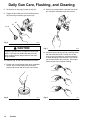
Daily Gun Care, Flushing, and Cleaning
WARNING
CAUTION
PRESSURIZED EQUIPMENT HAZARD
To reduce the risk of a serious injury whenever you
are instructed to relieve pressure, follow the Pressure Relief Procedure on page 13.
Clean all parts with a non-conductive solvent, compatible with the fluid being sprayed. Conductive
solvents can cause the gun to malfunction.
Methylene chloride with formic or propionic acid is
not recommended as a flushing or cleaning solvent
with this gun as it will damage nylon components.
CAUTION
Solvent left in gun air passages could result in a poor quality paint finish. Do not use any cleaning method which
may allow solvent into the gun air passages.
Do not point the gun up while cleaning it.
02056
Do not immerse the gun in solvent.
02057
Do not wipe the gun with a cloth soaked in
solvent; ring out the excess.
02027
Do not use metal tools to clean the air cap
holes as this may scratch them; scratches can
distort the spray pattern.
02055
General System Maintenance
1. Relieve the pressure.
2. Clean the fluid and air line filters daily.
3. Check for any fluid leakage from the gun and fluid
hoses. Tighten fittings or replace equipment as
needed.
14
308–293
4. Flush the gun before changing colors and whenever you are done operating the gun.
Daily Gun Care, Flushing, and Cleaning
WARNING
PRESSURIZED EQUIPMENT HAZARD
To reduce the risk of a serious injury whenever you
are instructed to relieve pressure, follow the Pressure Relief Procedure on page 13.
4. Point the gun down into a grounded metal container, and flush the gun with solvent until all traces
of paint are removed from the gun passages.
1. Relieve the pressure.
2. Disconnect the fluid supply hose (J) from the gun;
do not disconnect the air supply hose.
02053
Fig. 3
J
5. Turn off the solvent supply.
6. Relieve the pressure. Disconnect the solvent
supply.
7. Disconnect both the solvent (N) and air (D) supply
hoses from the gun.
Fig. 1
02052
D
3. Connect the solvent supply hose (N) to the gun.
N
Fig. 2
N
02051
02052
Fig. 4
308–293
15
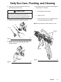
Daily Gun Care, Flushing, and Cleaning
8. Remove the air cap ring (12) and air cap (19).
12. With the gun pointed down, clean the front of the
gun, using the soft-bristle brush and solvent.
9. Trigger the gun while you remove the fluid nozzle
(20) from the gun with the gun wrench (35).
20
35
12, 19
02060A
Fig. 5
CAUTION
Fig. 7
Trigger the gun whenever you tighten or remove the
nozzle. This keeps the needle seat away from the
nozzle seating surface and prevents the seat from
being scratched.
10. Soak the ring, air cap, and fluid nozzle in solvent.
02062A
13. Scrub the the air cap ring, air cap, and fluid nozzle
with the soft-bristle brush. To clean out air cap
holes, use a soft implement, such as a toothpick,
to avoid damaging critical surfaces. Clean the air
cap and fluid nozzle daily, minimum. Some applications require more frequent cleaning.
11. Dip the end of a soft-bristle brush into a compatible
solvent. Do not continuously soak the brush’s
bristles with solvent and do not use a wire brush.
02007
Fig. 6
16
308–293
Fig. 8
02011
Daily Gun Care, Flushing, and Cleaning
14. Trigger the gun while you install the fluid nozzle
(20) with the gun wrench (35).
CAUTION
When tightening the nozzle, do not exceed 35 in-lbs
(4 NSm) torque. Over-tightening the nozzle can
cause the nozzle hex to round, can affect the spray
pattern, and is unnecessary to guarantee a seal.
15. Install the air cap ring (12) and air cap (19).
17. After cleaning the gun, lubricate the following parts
with lubricant 111–265 daily:
D
Fluid adjustment knob threads
D
Trigger pivot pin
D
Fluid needle shaft; refer to the Service section
to remove and reinstall the needle
NOTE: See Accessories to order lubricant 111–265.
20
35
12, 19
Lubricate
Fig. 9
02060A
16. Dampen a soft cloth with solvent and wring-out the
excess. Point the gun down and wipe off the
outside of the gun.
Lubricate
02019
Fig. 11
Fig. 10
02063
308–293
17
Troubleshooting
WARNING
PRESSURIZED EQUIPMENT HAZARD
To reduce the risk of a serious injury, follow the
Pressure Relief Procedure on page 13 before
checking or repairing any part of the gun or system.
PROBLEM
Fluid flow is fluttering while spraying
CAUSE
SOLUTION
1. Fluid nozzle not tight enough
1. Tighten fluid nozzle; Do not
exceed 35 in-lbs (4 Nm) torque.
2. Fluid filter clogged
2. Check fluid filter.
3. Fluid adjustment knob not
properly set
3. Turn the fluid adjustment knob
out for less feathering or use a
larger size nozzle.
4. Baffle (item 11) installed wrong
or damaged
4. Check if baffle protrusion is
properly inserted into gun insert
hole; see page 24. Replace
baffle if damaged.
1. Air hose size is too restricted for
higher air flows
1. Use larger 3/8 in. (9.5 mm) ID
air hose, part no. 185–353. See
Accessories.
2. Fluid pressure too low, causing
fluid flow to reduce when gun is
elevated
2. Raise fluid pressure at source or
use a smaller fluid nozzle.
No round pattern control
Baffle (item 11) installed wrong or
damaged
Check if baffle protrusion is properly
inserted into gun insert hole; see
page 24. Replace baffle if damaged.
Pattern becomes off-set or heavy
on ends
1. Fluid nozzle is over-tightened
1. Do not exceed 35 in-lbs (4 Nm)
torque on nozzle. Replace
nozzle if damaged.
2. Air cap too tight
2. Loosen air cap retaining ring.
3. Air cap horn holes plugged
3. Clean air cap horn holes with
non-metallic item such as a
toothpick.
There’s no fluid regulator, or air regulator on pressure pot is not sensitive enough at low pressures
Add low pressure fluid regulator, or
add more sensitive air regulator on
pressure pot.
Fluid flow fades while spraying high
viscosity fluids
Fluid system will not operate at low
enough fluid pressure [below 10 psi
(70, kPa, 0.7 bar)]
18
308–293
Notes
308–293
19
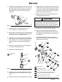
Service
Items Needed for Service
Gun Wrench – provided
Seal Installation Tool – provided
Adjustable Wrench
Screw Driver
Lubricant part no. 111–265; see Accessories to
order
Compatible Solvent
20
35
12, 19
NOTE:
Gun Repair Kit 236–007 is available. The kit includes the air valve assembly (14), ring packing
(22) u-cup seals (32, 33), and packing assembly
(39). See page 25 to order.
The following procedure covers the replacement of
all the parts included in the Gun Repair Kit.
The Optional M-1265 Spray Gun (part no. 236–020
to 236–022, 236–027 and 236–028) have a two
piece needle assembly, which includes a SST
needle shaft assembly and a SST needle tip,
instead of the one-piece needle shown in the
following instructions. See Chart 2 on page 5 for
part numbers.
WARNING
PRESSURIZED EQUIPMENT HAZARD
To reduce the risk of a serious injury, follow the
Pressure Relief Procedure on page 13 before
checking or repairing any part of the gun or system.
02060A
Fig. 1
4. Remove the fluid adjustment knob (8) and fluid
spring (16). See Fig. 5.
5. Pull the fluid needle (21) out the back of the gun.
6. Remove the trigger (3).
7. Remove the fluid adjustment nut (6), spring (15),
and air valve (14).
8. To remove the packing adjustment screw (31),
insert a thin-blade screw driver (A) through the
back of the gun and into the packing adjustment
screw (31) as shown in Fig. 2. Be careful not to
nick or damage parts with the tool.
Disassembly
1. Relieve the pressure.
2. Remove the air cap retaining ring (12) and air cap
(19).
A
31
3. Trigger the gun while you remove the fluid nozzle
(20) with the gun wrench (35). See Fig. 1.
CAUTION
Trigger the gun whenever you tighten or remove the
nozzle. This keeps the needle seat away from the
nozzle seating surface and prevents the seat from
being scratched.
20
308–293
02110
Fig. 2
Service
11. Clean the parts. Check the fluid needle (21) for
damage or excessive wear. Replace if necessary.
CAUTION
Do not use excessive force to push out the packing
assembly (39) or the u-cup seal (33) as this may
bend the fluid needle (21). Refer to Fig. 3 and 4. If
packings are difficult to remove, use a 3/16 in. plastic
rod to push them out.
9. Push the three piece packing assembly (39) out
toward the back of the gun, with the threaded end
of the fluid needle, as shown in Fig. 3.
12. Check the baffle (11) for damage. If it is damaged,
carefully pry it off with a screwdriver and replace it.
13. Lightly lubricate the parts indicated in Fig. 5 with
lubricant 111–265.
12
19
20
3
11
4
21
5
3
33
14
1
21
3
39 31
15
02109A
1
Fig. 3
10. Use the threaded end of the fluid needle (21) to
push out the u-cup seal (33) as shown in Fig. 4.
1
16
3
6
1
Lightly lubricate
2
Lightly lubricate threads
3
Torque to 35–40 in-lbs (3.9–4.5 Nm)
4
Be sure the baffle protrusion is properly inserted into
the gun insert hole before tightening the nozzle
2
8
02103A
Fig. 5
21
02022A
Fig. 4
308–293
21
Service
Assembly
1. Insert the fluid needle (21) through the front of the
gun as shown in Fig. 6. Install the new packing
assembly (39) by placing them on the end of the
needle tip. Orientate the packings as shown in
Fig. 6.
4. Place the new u-cup seal (33) on the seal installation tool (42) with the u-cup lips facing the tool as
shown in Fig. 8.
5. Push the packing (33) into the gun until a definite
snap is felt.
1
33
1
2
42
39
21
3
1
Washer
2
U-cup; lips face
down
3
Spreader
Fig. 6
2. Place the packing adjustment screw (31) over the
packing assembly and start the threads into the
gun. Then remove the needle.
3. Insert a thin-blade screw driver (A) through the
back of the gun and into the packing adjustment
screw (31) as shown in Fig. 7. Be careful not to
nick or damage parts with the tool. Turn the screw
with the screw driver (about 3 turns); the packing
will still be loose.
1
U-cup lips face the tool
02023
Fig. 8
6. Place the new air valve assembly (14) on the fluid
needle (21), against the nut (B). See Fig. 9. This
helps align the entrance of the air valve stem into
the inside diameter of the u-cup seal (33) without
damaging the seal lip.
7. Install the fluid needle (21) and the air valve
assembly (14) into the back of the gun.
21
14
A
B
31
02110
Fig. 7
22
308–293
Fig. 9
02108
Service
8. Tighten the packing adjustment screw (31) with the
gun wrench (35), as shown in Fig. 10, until you can
feel a slight drag on the fluid needle. Do not overtighten the screw as this may bind the needle
movement.
16. Trigger the gun to test the needle movement. If the
needle does not return after the trigger is released
or is slow in returning, loosen the packing adjustment screw (31) with the gun wrench (35) until the
needle returns freely. See Fig. 10.
17. Trigger the gun while you install the fluid nozzle
(20) with the gun wrench (35).
31
35
CAUTION
02104A
Fig. 10
When tightening the nozzle, do not exceed 40 in-lbs
(4.5 Nm) torque. Over-tightening the nozzle can
cause the nozzle hex to round, can affect the spray
pattern, and is unnecessary to guarantee a seal.
18. Install the air cap ring (12) and air cap (19).
9. Install the trigger (3). Torque the screw (5) to
10–15 in-lbs (1.1–1.7 Nm). See Fig. 12.
10. Remove the u-cup seal (32) from the fluid adjustment
nut (6). See Fig. 11. Be careful not to damage the
seal surface or the nut’s internal threads.
11. Install the new u-cup seal (32) with the seal installation tool (42); the u-cup lips must face toward the
tool as shown in Fig. 11. This will help apply even
pressure to the u-cup lips and avoid damaging
them.
19. Make sure the gun fluid packing assembly is
sealing properly by spraying solvent at low pressure before fully pressurizing the gun with the fluid
to be sprayed.
If the fluid packing leaks, tighten the packing
adjustment screw (31) slightly and retest until the
packing seals completely.
12
19
12. Push the u-cup seal (32) into the fluid adjustment
nut (6) until a definite snap is felt.
20
3
11
4
5
13. Install the new packing ring (22).
6
33
1
U-cup lips face
the tool
14
1
42
21
1
22
32
1
3
6
39 31
15
1
02021
Fig. 11
14. Install the spring (15) and fluid adjustment nut (6).
Torque the nut to 25–35 in-lbs (2.8–4.0 Nm). See
Fig. 12.
15. Install the spring (16) and fluid adjustment knob (8).
16
1
Lightly lubricate
2
Lightly lubricate threads
3
Torque to 35–40 in-lbs (3.9–4.5 Nm)
4
Be sure the baffle protrusion is properly inserted into
the gun insert hole before tightening the nozzle
5
Torque to 25–35 in-lb (2.8–4.0 Nm)
6
Torque to 10–15 in-lb (1.1–1.7 Nm)
5
6
2
8
02103A
Fig. 12
308–293
23
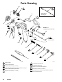
Parts Drawing
19
20
9
21
Needle set for
optional guns
34
2
5
12
8
5
11
13dn
13b
4
10
1
25
3
Ref No. 13
Includes items 13a–13d
13cn
13a
4
33*
39*
6
3
14*
21
1
1
Needle for
standard guns
31n
1
15
1
16
7
32*
22*
3
6
35
2
42
8
02025A
1
Lightly lubricate
6
U-cup lips face air valve (14)
2
Lightly lubricate threads
7
U-cup lips face spring (16)
3
Torque to 25–35 in-lbs (2.8–4.0 NSm)
8
Optional gun hook to replace plate (34)
4
Be sure the baffle protrusion is properly inserted into the gun
insert hole before tightening the nozzle
9
Torque to 35–40 in-lb (3.9–4.5 NSm)
5
Torque to 10–15 in-lbs (1.1–1.7 NSm)
10
Torque the screw or any accessory installed in this port to
4–6 in-lb (0.35–0.53 NSm)
24
308–293
Parts List
Part No. 236–013 to 236–016, Series B
M-1265 Standard HVLP Spray Gun
With standard needle, nozzle, and air cap
Includes items 1–42
Part No. 236–023 and 236–024, Series B
M-1265 Optional Non-HVLP Compliant Spray Gun
With standard needle and nozzle and
optional high pressure air cap
Includes items 1–42
Part No. 236–020 to 236–028, Series B
M-1265 Optional HVLP Spray Gun
With optional needle, nozzle, and air cap
Includes items 1–42
Ref
No.
Part No.
Description
1
2
3
4
5
236–004
275–852
185–761
185–746
203–953
6
8
11
12
13
188–490
185–745
275–851
276–278
236–006
GUN BODY
HOOK, gun
TRIGGER, two-finger
PIN, pivot; 10-24 UNC-2B
SCREW, lock; No. 10–24 UNC-2A
x 0.375 in.
NUT, fluid adjustment
KNOB, fluid adjustment
BAFFLE, pattern
RETAINING RING, air cap
PATTERN ADJUSTMENT VALVE
ASSY.; Includes items 13a–13d
S VALVE, pattern adjustment
S NUT, air adjustment
S O-RING, split; PTFE
S RETAINING RING
AIR VALVE ASSY.
SPRING, compression
SPRING, compression
AIR CAP
FLUID NOZZLE
FLUID NEEDLE
RING PACKING, PTFE r
PLUG
SCREW, packing adjustment
SEAL, u-cup, nut; UHMWPE
13a
13b
13cn
13dn
14*
15
16
19.
20.
21.
22*
25
31n
32*
188–492
188–700
187–699
105–456
236–009
111–291
110–402
–
–
–
188–694
108–382
188–665
110–453
Qty
1
1
1
1
1
1
1
1
1
1
1
1
1
1
1
1
1
1
1
1
1
1
1
1
Ref
No.
Part No.
Description
33*
34
35
39*
188–493
275–853
188–666
236–008
42
276–268
SEAL, u-cup; UHMWPE
PLATE, gun
WRENCH, gun
PACKING ASSY.; includes
u-cup spreader, u-cup seal
and packing washer
TOOL, seal installation
Qty
1
1
1
1
1
* These parts are included in Repair Kit 236–007,
which may be purchased separately.
n Keep these spare parts and the Repair Kit on hand
to reduce down time.
. See selection charts for your gun model on pages
4 and 6 to order air caps, fluid nozzles, and fluid
needles.
Manual Change
Summary
Changed the Selection Charts to reflect the Series B
gun parts.
308–293
25
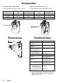
Accessories
Cleaning Brush 105–749
For use in cleaning gun
Air Hose Quick-disconnect
Install between gun air inlet fitting and air hose.
208–536
169–970
Lubricant 111–265
One 4 oz. (113 gram) tube sanitary (non-silicone)
lubricant for fluid seals and wear areas.
Fluid Hose Assembly 205–142
300 psi (2.1 MPa, 21 bar) Maximum Working Pressure
Nylon with neoprene cover, 0.25 in. (2.4 mm) ID,
3/8 npsm(fbe), 25 ft. (7.6 m) long
Fluid Tube Kit 236–318
Allows air and fluid hoses to be
more easily strapped together
and eases gun movement by
the operator.
03405
High Pressure Air Cap 189–755
Optimal air cap for use in non-HVLP compliant operations. Water-base compatible
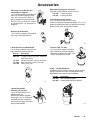
Air Pressure Verification Kit 224–187
For use in checking gun atomizing air pressure at
various supply air pressures. Not to be used for
actual spraying.
Assemble kit as shown in
drawing below. Screw
tube connector into gun’s
side port. Turn on the air
to the gun, then trigger the
gun and read the resulting air pressure.
NOTE: To be “HVLP compliant”, the atomizing air
pressure must not exceed 10 psi (70 kPa, 0.7 bar).
SST Fluid Pressure Regulator
100 psi (0.7 MPa, 7 bar) Maximum Inlet Pressure
3–30 psi (21–210 kPa, 0.2–2.1 bar)
Regulated Pressure Range
To regulate the fluid pressure to the gun.
1/4 npt(f) inlet and outlet
236–081
236–449
Air Filter and Moisture Separator 106–149
250 psi (1.7 MPa, 17.4 bar) Maximum
Working Pressure
Removes moisture, oil, and other contaminants from the compressed air supply.
1/2 npt(fbe)
Air Pressure Regulator Kit 210–613
300 psi (2.1 MPa, 20 bar) Maximum
Inlet Pressure
0-125 psi (0–0.87 MPa, 0-8.75 bar)
Regulated Pressure Range
To regulate the air pressure to the gun.
Includes gauge, air shutoff valve, and
fittings. 1/4 npt(m)
Air Hose Assembly 185–353
100 psi (0.7 MPa, 7 bar) Maximum Working Pressure
Optional air hose for use when higher air flow is
required. 25 ft. (7.625 m) long, 3/8 in. (9.53 mm) ID,
1/4 npsm(f) swivel, buna-n
308–293
0135
Air Shutoff Valve 208–390
500 psi (3.4 MPa, 34 bar) Maximum Working Pressure
To shutoff air supply line. 1/4 npt(m)
Gun Air Regulator Assy. 235–119
0–100 psi (0–0.7 MPa, 0–7 bar) air
regulator to control air to gun
Regulator without
pressure gauge
Regulator with pressure gauge
Air Hose Assembly 210–867
100 psi (0.7 MPa, 7 bar) Maximum Working Pressure
25 ft. (7.625 m) long, 5/16 in. (7.94 mm) ID, 1/4
npsm(f) swivel, buna-n
26
Coupler, 1/4 npt(f)
Nipple, 1/4 npt(m)
01727
SST Pressure Cup Kit 235–373
with single air regulator
1 qt. (0.95 liter) capacity, 304 stainless
steel cup. Includes a pressure relief
valve and a single air regulator and
gauge.
01725
Accessories
SST Pressure Cup Kit 235–374
with double air regulator
1 qt. (0.95 liter) capacity, 304 stainless
steel cup. Includes a pressure relief
valve, a 0–100 psi (0–0.7 MPa, 0–7
bar) air regulator for gun atomization,
and a 0–15 psi (0–104 kPa, 0–1.0 bar)
air regulator for the 1 qt. pressure cup
supply air.
Disposable Polyethylene Cup Liners
Paint and solvent resistant. 40 liners per box.
112–490
112–491
01726
1 Quart Cup Size
2 Quart Cup Size
2 Quart Pressure Cup 214–627
2 qt. (1.94 liter) capacity, aluminum cup
Includes air pressure regulator and gauge, 4 ft. (1.2 m)
length air and fluid hose with 1/4 npsm(f) swivel ends,
pressure relief valve, and rigid hook handle.
Gravity Cup Kit 236–038
7.5 oz. (220 cc) capacity, 430 stainless
steel cup, 3/8 npsm(f) fluid inlet
0125
0123
1 Quart Pressure Cup Kit 224–426
1 qt. (0.95 liter) capacity, aluminum cup
Some assembly required. Includes:
Pressure Tank 171–226
2.5 gal (9.5 liter) capacity, aluminum
tank. Includes air pressure regulator
and gauge, pressure relief valve, pickup tube, and rigid hook handle.
Part No.
Description
224–419
1 Quart Pressure Cup Assy., aluminum
(with check valve)
Female Connector, 1/8 npt x 5/32 tube
Male Connector, 10-32 x 5/32 tube
Tubing, 5/32” OD
111–324
111–328
187–169
0122
Husky 307 HVLP Systems
Includes Husky 307 Pump, Pail Cover, Air Regulators,
Suction Tube and Inlet Filter, Fluid Regulator, Fluid
Recirculation Line, and Air and Fluid Hoses
0166
1 Quart Remote SST
Pressure Cup 235–054
1 qt. (0.95 liter) capacity, 304
stainless steel cup.
Includes air pressure regulator
and gauge, 4 ft. (1.2 m) length air
and fluid hose with 1/4 npsm(f)
swivel ends, pressure relief valve,
and rigid hook handle.
Part No.
Description
224–833
235–659
SST Pail Mount System
Carbon Steel Pail Mount System
01962
01526
308–293
27
Accessories
Low Pressure SST Pressure Tanks
High Pressure SST Pressure Tanks
For fluid pressures up to 15 psi (104 kPa, 1.0 bar)
For fluid pressures up to100 psi (700 kPa, 7 bar)
gallons (liters)
Tank Size
Low Pressure Tank
P/N
Low Pressure Tank
with Agitator P/N
High Pressure Tank High Pressure Tank
P/N
with Agitator P/N
5 (19)
236–143
236–146
236–149
236–152
10 (38)
236–144
236–147
236–150
236–153
15 (57)
236–145
236–148
236–151
236–154
Low Pressure Tank
High Pressure Tank
with Agitator
03084
03189
Dimensions
Technical Data
6.39 in.
(163 mm)
6.9 in.
(175 mm)
Category
Data
Maximum Working Fluid
Pressure
100 psi (0.7 MPa, 7 bar)
Maximum Working Air
Pressure
100 psi (0.7 MPa, 7 bar)
Maximum Compliant
Inbound Air Pressure
65 psi (444 kPa, 4.4 bar)
Fluid and Air Operating
Temperature Range
32 F to 140 F (0 C to
60 C)
Weight
14.9 oz. (422 g)
Air Inlet
1/4–18 npsm (R1/4–19)
compound thread
Fluid Inlet
3/8–18 npsm (R3/8–19)
compound thread
Wetted Parts
304 and 17–4 PH
Stainless Steel
02018
Noise Data*
Sound Pressure at 65
psi (444 kPa, 4.4 bar)
Sound Power at 65 psi
(444 kPa, 4.4 bar):
*
28
308–293
95 Db(A)
101 Db(A)
All readings were taken with the gun controls fully open
at the assumed operator position. Sound pressure was
tested to CAGI–PNUEROP–1969. Sound power was
tested to ISO 3744–1981.
Notes
308–293
29
Notes
30
308–293
Notes
308–293
31
Graco Warranty and Limitation of Liability
WARRANTY
Graco warrants all equipment listed in this manual which is manufactured by Graco and bearing its name to be free from defects
in material and workmanship on the date of sale by an authorized Graco distributor to the original purchaser for use. Graco will,
for a period of twelve months from the date of sale, repair or replace any part of the equipment determined by Graco to be defective. This warranty applies only when the equipment is installed, operated and maintained in accordance with Graco’s written recommendations.
This warranty does not cover, and Graco shall not be liable for general wear and tear, or any malfunction, damage or wear
caused by faulty installation, misapplication, abrasion, corrosion, inadequate or improper maintenance, negligence, accident,
tampering, or substitution of non-Graco component parts. Nor shall Graco be liable for malfunction, damage or wear caused by
the incompatibility of Graco equipment with structures, accessories, equipment or materials not supplied by Graco, or the improper design, manufacture, installation, operation or maintenance of structures, accessories, equipment or materials not supplied by Graco.
This warranty is conditioned upon the prepaid return of the equipment claimed to be defective to an authorized Graco distributor
for verification of the claimed defect. If the claimed defect is verified, Graco will repair or replace free of charge any defective
parts. The equipment will be returned to the original purchaser transportation prepaid. If inspection of the equipment does not
disclose any defect in material or workmanship, repairs will be made at a reasonable charge, which charges may include the
costs of parts, labor, and transportation.
THIS WARRANTY IS EXCLUSIVE, AND IS IN LIEU OF ANY OTHER WARRANTIES, EXPRESS OR IMPLIED, INCLUDING
BUT NOT LIMITED TO WARRANTY OF MERCHANTABILITY OR WARRANTY OF FITNESS FOR A PARTICULAR PURPOSE.
Graco’s sole obligation and buyer’s sole remedy for any breach of warranty shall be as set forth above. The buyer agrees that no
other remedy (including, but not limited to, incidental or consequential damages for lost profits, lost sales, injury to person or property, or any other incidental or consequential loss) shall be available. Any action for breach of warranty must be brought within two
(2) years of the date of sale.
GRACO MAKES NO WARRANTY, AND DISCLAIMS ALL IMPLIED WARRANTIES OF MERCHANTABILITY AND FITNESS
FOR A PARTICULAR PURPOSE IN CONNECTION WITH ACCESSORIES, EQUIPMENT, MATERIALS, OR COMPONENTS
SOLD BUT NOT MANUFACTURED BY GRACO. These items sold, but not manufactured by Graco (such as electric motors,
switches, hose, etc.) are subject to the warranty, if any, of their manufacturer. Graco will provide purchaser with reasonable assistance in making any claim for breach of these warranties.
For Sales to Canadian Customers:
Except as expressly stated herein, Graco makes no representations, warranties or conditions, express, implied or collateral, concerning any goods or services sold, and GRACO SHALL NOT BE LIABLE IN ANY MANNER FOR any other representation,
warranty or condition of any kind, whether arising by operation of law or otherwise, including but not limited to, WARRANTIES OF
MERCHANTABLE QUALITY OR FITNESS FOR A PARTICULAR PURPOSE.
LIMITATION OF LIABILITY
In no event will Graco be liable for indirect, incidental, special or consequential damages resulting from Graco supplying equipment hereunder, or for the furnishing, performance, or use of any products or other goods sold hereto, whether due to a breach of
contract, breach of warranty, the negligence of Graco, or otherwise.
Graco Phone Numbers
TO PLACE AN ORDER, contact your Graco distributor, or call this number to identify the distributor closest to you:
1–800–367–4023 Toll Free
All written and visual data contained in this document reflects the latest product information available at the time of publication.
Graco reserves the right to make changes at any time without notice.
Sales Offices: Minneapolis, Detroit, Los Angeles
Foreign Offices: Belgium, Canada, England, Korea, France, Germany, Hong Kong, Japan
GRACO INC.
P.O. BOX 1441 MINNEAPOLIS, MN
55440–1441
PRINTED IN U.S.A. 308–293 May 1993, Revised February 1997
32
308–293