1
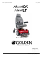
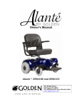
Owner’s Manual Front Wheel Drive Power Chairs Models GP204/GP215 YOUR LIFE IN MOTION Golden Technologies - 401 Bridge Street - Old Forge, PA 18518 - Tel: 800-624-6374 - Fax: 800-628-5165 - www.goldentech.com Alante DX/LT Owner’s Manual Rev A_011811 Alante DX/LT Owner’s Manual Rev A_011811 Thank you for purchasing your Alante DX/LT™ power chair. We are honored you have chosen Golden Technologies for your mobility needs. Alante DX/LT™ Models GP204/GP215 Standard Packing List: 1 Owner’s Manual Base with Battery Pack 1 Seat 2 Seat Arms 1 Seat Belt 1 Battery Charger Seat Post Nut and Bolt DISCLAIMER We ask that you read this manual completely before operating your new Alante DX/LT. Golden Technologies, Inc. is not and cannot be held responsible for any damage or injury incurred due to improper or unsafe use of the Golden Alante DX/LT, power chair. Golden Technologies, Inc. specifically disclaims responsibility for any bodily injury or property damage that may occur during any use that does not comply with applicable federal, state, or local laws or ordinances. 2 Alante DX/LT Owner’s Manual Rev A_011811 FOR YOUR RECORDS Please fill in your Alante DX/LT™ information below. This information will be useful in the event that you ever need to contact Golden Technologies, Inc. concerning your power chair. Your Alante DX/LT ™ Model ____________________ Serial Number __________________________ Date of Purchase ___________________ Body Color __________________ Options ______________________ Your Golden representative or dealer Name __________________________________________ Company ______________________________________ Address ___________________________________________________________ Please remember to fill in and return your warranty registration card. Tools Required: The following tools will allow you to make all comfort adjustments to your power chair. 2 – 13mm wrenches 17mm wrench 12mm wrench 10mm wrench 8mm Allen wrench 5mm Allen wrench 4mm Allen wrench 3 Alante DX/LT Owner’s Manual Rev A_011811 CONTENTS I. Introduction........................................................................................................ 5-6 II. Safety……………………………………………………………………………………………… 7-10 III. EMI/RFI………………………………………………………………………………………….. 11 IV. Assembly of your GP204/GP215…………………………………………………………. 12-17 V. Disassembly of your GP204/GP215……………………………………………………...... 18 VI. Comfort Settings……………………………………………………………………………… 19-24 VII. Operation/Diagnostics/Troubleshooting………………………………………………. 25-32 VIII. Battery Charging……………………………………………………………………………. 33-34 IX. Care and Maintenance of your GP204/GP215……………………………………………35 X. Riding Your Alante DX/LT™……………………………………………………………….. 36-37 XI. Technical Specifications GP204/GP215………………………………………………… 38-39 XII. Warranty..…………………………………………………………………………………….. 40-41 Warranty/Registration Card……………………………………………………………………… 42 4 Alante DX/LT Owner’s Manual Rev A_011811 I. INTRODUCTION Congratulations on the purchase of your new Alante DX/LT™ power chair. The Alante DX/LT, combines cutting edge technology with attractive designs that are also highly functional in today’s world. We at Golden Technologies, Inc. know that you have chosen a power chair that will give you years of dependable operation and also will enhance the quality of your life by providing you with the mobility to experience an active daily lifestyle. Even though your new Alante DX/LT is both user-friendly and designed for maximum maneuverability in even the tightest spaces, we ask that you please read, understand and follow all of the instructions and suggestions in this manual before you operate your Alante DX/LT for the first time. The safe use of your new power chair is very important to us. If you feel that you do not understand the instructions and suggestions presented in this owner’s manual, or if, for any reason, you do not feel capable of performing the activities necessary to assemble, disassemble, operate, or maintain your Alante DX/LT, please contact your local Golden Technologies, Inc. dealer or call Golden Technologies, Inc. Technical Support Services at (800) 624-6374. Golden Technologies, Inc. cannot be held responsible for personal injury or property damage resulting from the unsafe or the improper use of any of our broad range of health and personal mobility products. Also, Golden Technologies, Inc. cannot be held responsible for personal injury or property damage resulting from attempts to follow instructions, suggestions, and guidelines presented in this owner’s manual. Our Research and Development Department, our Quality Control Department, and our Engineering Department have used the latest product specifications and the latest product design information to manufacture your Alante DX/LT. Golden Technologies, Inc. reserves the right to implement changes into our product lines when those changes become desirable or necessary. If changes are implemented into our product line, there may be minor differences between the product you purchased and the illustrations and instructions in this owner’s manual. Please fill out and mail the enclosed warranty registration card. Registration is also available @ www.goldentech.com. We at Golden Technologies, Inc. would appreciate hearing about the dependability of your Alante DX/LT and about the convenience of mobility it has provided for you. We would also appreciate hearing about the service you received from your local Golden Technologies, Inc. dealer or representative. Golden Technologies, Inc. 401 Bridge Street Old Forge, PA 18518 Phone: (570) 451-7477 Fax: (570) 451-7494 Toll free: (800) 624-6374 For more information about our products and services or to send us your comments, please visit our website at www.goldentech.com 5 Alante DX/LT Owner’s Manual Rev A_011811 I. INTRODUCTION ACCESSORIES FOR THE Alante DX/LT™ POWER CHAIR: A variety of accessories are available for your Golden Alante DX/LT Power chair. Please contact your Authorized Golden Technologies Dealer for more information or to order. • • • • • • • • Cane Holder Tube Cup Holder Deluxe Pack N’ Go Forearm Crutch Holder Safety Flag Power chair Cover Touch-up Paint Swing-Away Joystick Bracket (Optional) *Some accessories require a mounting bracket or mounting clips. Please check with your dealer to find out if the accessory you would like to order requires a mounting bracket or mounting clips. 6 Alante DX/LT Owner’s Manual Rev A_011811 II. SAFETY Your Golden Alante DX/LT™ is a battery-operated personal mobility vehicle. Please exercise caution and consideration when you are operating it. Driving your Alante DX/LT carefully and thoughtfully will help ensure your personal safety and the safety of other people. Note: Before learning to operate your Alante DX/LT, have your Golden Technologies, Inc. representative determine if it is advisable for you to practice getting on and off your power chair and operating it in the presence of an attendant. BEFORE getting on your Alante DX/LT • Check to be certain that the power is turned OFF. See “Operation” section on pages 2330. This will eliminate the possibility of accidentally activating the joystick and causing injury to you or to others. • Check to be certain that your Alante DX/LT is not in the freewheel mode. See the “Operation” section of pages 23-30. • Flip up the armrests. • If your chair is equipped with swing away leg rests, move them to the sides. • If your chair is equipped with a footrest, flip it to the “up” position. Getting ON your Alante DX/LT • • • • Carefully seat yourself comfortably and securely on the seat. Adjust the leg rests or flip down the footrest. Flip down the armrests. Fasten the seat belt. Getting OFF your Alante DX/LT • • • • • Make certain that the power is turned off. Unfasten the seat belt. Flip up the armrests. Flip up the footrest, or move the leg rests to the sides. Carefully stand and step away from the chair. MAXIMUM WEIGHT Your Alante DX/LT has been rated to a maximum payload (passenger and anything else being carried on the power chair) of 300 pounds. Exceeding the maximum weight rating will void your warranty. Exceeding the maximum weight capacity will void your warranty and may result in injury to yourself and/or others. 7 Alante DX/LT Owner’s Manual Rev A_011811 II. SAFETY DRIVING ON AN INCLINE • Drive with caution when attempting to negotiate any incline, even handicap access ramps. • Always climb or descend a gradient by driving straight up or straight down the face of the slope. • Do not traverse or drive across the face of a gradient. • Do not attempt to negotiate an incline that is covered with snow, ice, cut or wet grass, leaves, or any other potentially hazardous material. • Do not back down an incline. • Try to keep your Alante DX/LT moving when climbing an incline. If you do come to a stop, restart and accelerate slowly and carefully. • Do not try to descend or climb a slope whose gradient is greater than recommended. See “Specifications” section. IF, WHILE YOU ARE DRIVING DOWN A SLOPE, YOUR POWER CHAIR STARTS TO MOVE FASTER THAN YOU FEEL IS SAFE, RELEASE THE JOYSTICK LEVER AND ALLOW YOUR ALANTE DX/LT TO COME TO A STOP. WHEN YOU FEEL THAT YOU AGAIN HAVE CONTROL OF YOUR POWER CHAIR, PUSH THE JOYSTICK LEVER FORWARD AND CONTINUE SAFELY DOWN THE REMAINDER OF THE SLOPE. MEDICATION Always check with your physician to determine if any of the medications you are taking may affect your judgment and/or your ability to operate your Alante DX/LT™. Also check with your physician concerning your physical ability to operate a power chair. 8 Alante DX/LT Owner’s Manual Rev A_011811 II. SAFETY SAFETY RULES • Do not attempt to use your Alante DX/LT on an escalator. Always use an elevator. • Do not carry passengers on your power chair. • Do not operate your Alante DX/LT, if it is not functioning properly. • Use caution when driving on soft or uneven surfaces such as grass, gravel and on decks where there is no railing. • Never drive on the roadway, except when you must cross the street. • Cross streets at intersections and use the most direct route, making sure that your path is clear and that you are visible to motor traffic. • It is not recommended to drive your Alante DX/LT, up or down a step or curb that is higher than 1-1/2 inches. • Never back up or down a step or curb. • Never operate your Alante DX/LT, while you are under the influence of alcohol. • Do not operate or store your power chair where it will be exposed to rain, snow, mist and below-freezing temperatures. • Do not operate your power chair on slippery, icy or salted surfaces. • Never sit on your power chair when it is in freewheel mode and on an incline or decline. • Never place your power chair into freewheel mode without a trained assistant present. • Do not modify your power chair in any way that is not authorized by Golden Technologies, Inc. • Do not disassemble the tire. If disassembly is required, have your authorized Golden Technologies dealer perform any necessary maintenance or repair. • Do not attempt to inflate the tires of your Alante DX/LT. Your power chair is equipped with foam-filled flat free tires that do not require inflation. 9 Alante DX/LT Owner’s Manual Rev A_011811 II. SAFETY Please be sure to follow this important warning when transferring onto or off the Golden Alante DX/LT power wheelchair: DO NOT CONNECT OR ALLOW ANYONE EXCEPT AN AUTHORIZED GOLDEN TECHNOLOGIES REPRESENTATIVE TO CONNECT ANY ELECTRICAL OR MECHANICAL DEVICE TO YOUR ALANTE DX/LT. UNAUTHORIZED ACCESSORIES WILL VOID THE WARRANTY AND MAY CAUSE INJURY. TURNING TOO SHARPLY AROUND A CORNER CAN CAUSE THE POWER CHAIR TO TIP. AVOID THIS DANGER AT ALL TIMES BY STEERING A WIDE ARC AROUND CORNERS AND OBSTACLES. ALSO, TO AVOID THE RISK OF TIPPING, REDUCE SPEED BEFORE NEGOTIATING ANY TURNS. 10 Alante DX/LT Owner’s Manual Rev A_011811 III. EMI/RFI The rapid development of electronics, especially in the area of communications, has saturated our environment with electromagnetic (radio) waves that are emitted by television transmitters, cellular phones, citizen’s band radios (CBs) amateur radios (HAM radios), wireless computer links, microwave transmitters, paging transmitters, etc. These electromagnetic (EM) waves are invisible and increase in strength the closer one gets to the source of transmission. When these energy waves act upon electrical devices and cause them to malfunction or to function in an erratic or uncontrolled manner, they are referred to as Electromagnetic Interference (EMI) or Radio Frequency Interference (RFI). EMI/RFI AND YOUR Alante DX/LT™ All electrically powered vehicles, including power chairs are susceptible to EMI/RFI. This interference could result in abnormal or unintended movement of your Golden Alante DX/LT. Unintended movement or brake release could cause an accident or injury. The FDA has determined that each make and model of power chair can resist EMI/RFI to a certain level. The higher the level of immunity, the greater the degree of protection from EMI/RFI measured in volts per meter (V/m). The FDA has also determined that current technology is capable of providing 20 V/m of immunity to EMI/RFI, which would provide useful protection against common sources of interference. This product has been tested and has passed an immunity level of 20 V/m. EMI/RFI RECOMMENDATIONS • Do not turn on or use hand-held personal electronic communication devices such as cellular phones, walkie-talkies, or CB radios while your power chair is turned on. • Be aware of any nearby transmitters (radio, television, microwave, etc.) on your intended route and avoid operation your of power chair close to any of those transmitters. • Turn off the power if your Alante DX/LT is going to be in a stationary position for any length of time. • Be aware that adding accessories or components or modifying your power chair may make it more susceptible to EMI/RFI. • If unintended movement or brake release occurs, turn your power chair off as soon as it is safe to do so. • Report all incidents of unintended movement or brake failure to your Golden Technologies representative or to Golden Technologies. TURN OFF YOUR POWER CHAIR AS SOON AS IT IS SAFELY POSSIBLE IF UNINTENDED OR UNCONTROLLABLE MOTION OCCURS OR IF UNINTENDED BRAKE RELEASE OCCURS. 11 Alante DX/LT Owner’s Manual Rev A_011811 IV. ASSEMBLY Your Alante DX/LT is shipped partially disassembled in order to maximize the protection of all its parts during the shipping process. Please follow the instructions below to quickly and easily assemble the power chair for your use. NOTE: You will need only basic tools. If you do not have the required tools, or if you do not feel capable of safely assembling your power chair, please contact your local Golden Technologies, Inc. representative. Main Components 1. Base 2. Battery Pack 3. Seat Assembly 4. Seat Belt 5. Joystick 6. Foot Plate Joystick Seat Assembly Seat Belt Battery Pack Base Foot Plate Figure 1 12 Alante DX/LT Owner’s Manual Rev A_011811 IV. ASSEMBLY Before operating or assembling your Alante DX/LT, be sure to remove the battery contact insulator under the battery box. Your Alante DX/LT will not power up or operate with the insulator in place. 1. Grasp the battery box handle and lift the battery pack from the unit. Figure 2 Figure 3 2. Remove the rectangular black fabric insulator from the unit. 3. Replace the battery pack. Be sure it is securely in place. Note: The Alante DX battery pack weighs 30 pounds, and the Alante LT battery pack weighs 27 pounds. The seat for either unit weighs 36 pounds. Please ask for help if you do not feel capable of safely lifting that much weight. Seat Installation 1. Fold the seat back down. Figure 4 13 Alante DX/LT Owner’s Manual Rev A_011811 IV. ASSEMBLY - cont. 2. Pull up on the seat rotation lever, and while holding the lever; lift the seat and align the seat pin with the hole in the seat post. Figure 5 3. Insert the seat into the seat post and release the lever. Figure 6 4. Move the seat from side to side until it drops into place facing forward. Note: To rotate your seat, pull up on the seat rotation lever and rotate the seat to the desired position. Release the handle to lock the seat in position. 14 Alante DX/LT Owner’s Manual Rev A_011811 IV. ASSEMBLY The seat assembly weighs 36 pounds. Please ask for help if you do not feel capable of safely lifting that much weight. Removal of arms will reduce the weight of the seat. Be sure the seat is correctly installed and locked before operating your power chair Arm and Seat Belt Installation 1. Use a 4mm Allen wrench to remove the arm width adjustment screw from the arm receiver tube at the bottom rear of the seat frame. See figure 7. 2. Insert the arm into the arm receiver tube, so that the arm pad faces toward the front of the unit. Figure 7 3. Adjust the width of the arm. 4. Insert the arm width adjustment screw (provided with the seat belt) through the anchor, and secure by tightening the adjustment screw. See figure 8. Figure 8 5. Repeat steps 1 – 4 for the opposite side. 15 Alante DX/LT Owner’s Manual Rev A_011811 IV. ASSEMBLY Joystick Installation 1. Insert the joystick mounting tube into one of the mounting tubes under the armrest pads. Battery Charge LED Array Speed Setting LED Array ON-OFF Button Horn Button Speed Setting SLOWER Speed Setting FASTER Joystick mounting tube Mounting tube (Arm) Joystick adjustment screw Top View Bottom View Figure 9 2. Adjust the position of the joystick to a comfortable spot. 3. Tighten the joystick adjustment screw with a 4mm Allen wrench. Joystick adjustment screw Figure 10 4. Secure the joystick cable to the arm with the cable retaining straps. 16 Alante DX/LT Owner’s Manual Rev A_011811 IV. ASSEMBLY - cont. 5. Plug the joystick cable into the controller cable. Figure 11 Note: The joystick may be installed on the left or right arm according to your preference. Be sure the joystick cable and controller cables are securely attached to the unit and that the cables are not able to trail on the ground or become entangled on any surrounding objects while the unit is in use. 17 Alante DX/LT Owner’s Manual Rev A_011811 V. DISASSEMBLY To disassemble your Alante DX/LT ™, simply reverse the assembly process. See pages 13-17. Make certain that the controller power is turned off and that the chair is NOT in freewheel mode before attempting to perform disassembly. Note: The battery pack weighs 30 pounds on the Alante DX and 27 pounds on the Alante LT. Please get help if you do not feel capable of safely lifting that much weight. Battery Replacement Should your battery need replacement; please contact your Golden Technologies representative. Battery replacement requires disassembly of the battery pack and must be performed by a qualified technician. Battery Pack Figure 12 18 Alante DX/LT Owner’s Manual Rev A_011811 VI. COMFORT SETTINGS You may be spending a great deal of time on your Alante DX/LT™. To provide you with the maximum seating comfort, Golden Technologies, Inc. has designed this power chair to incorporate the following adjustments for operator comfort. COMFORT SETTINGS 1. Seat height 2. Headrest height 3. Backrest angle 4. Arm height 5. Arm width 6. Armrest angle 7. Footrest angle 8. Joystick bracket length 9. Joystick position Make certain that the power to your Alante DX/LT ™ is turned off before making any adjustments, to eliminate the risk of the joystick being accidentally bumped and activating the power chair. Seat Height Adjustment The seat is a center post design that is easily adjusted for height. To adjust the height to a comfortable level: 1. 2. 3. 3. Remove the seat. Place a 17mm wrench on the lock nut, and insert an 8mm Allen wrench into the bolt. Loosen and remove the bolt, washers and lock nut, noting their placement. Set the seat post to one of the three adjustment positions. Bolt, washers, and lock nut. Figure 13 5. Replace the bolt, washers and lock nut in the same order you remove them and tighten securely. 19 Alante DX/LT Owner’s Manual Rev A_011811 VI. COMFORT SETTINGS Headrest Height Adjustment 1. Standing behind the chair, push and then release the clamp on the left post of the headrest while you are pulling up or pushing down on the head rest. See figure 14. 2. The headrest will “click” to a stop in one of the preset positions. 3. Repeat step 1 until the headrest is at the desired height. Figure 14 Backrest Angle Adjustment (Refer to figure 15) 1. Place a 10 mm wrench on the lock nut and use a 5mm Allen wrench to loosen the bolt. 2. Remove the bolt and place it into the desired position. Note, that there are four angle positions available, 90 degrees to 120 degrees. 3. Replace the lock nut and tighten. Figure 15 Note: The backrest can be folded down to minimize chair height during transport. 20 Alante DX/LT Owner’s Manual Rev A_011811 VI. COMFORT SETTINGS Arm Height Adjustment 1. Loosen the arm height adjustment screws located on the back of the arm. Adjustment screw (4mm) Arm Figure 16 2. Lift the arm to the desired height making sure not to exceed the maximum height of the arm. 3. Tighten the arm height adjustment screw to secure the arm. 4. Repeat steps 1-3 to adjust the opposite arm. Adjustment screw (4mm) Figure 17 Arm Width Adjustment 1. Use a 4mm Allen wrench to loosen the adjustment screw at the lower rear of the seat. Adjustment screw (4mm) Figure 18 21 Alante DX/LT Owner’s Manual Rev A_011811 VI. COMFORT SETTINGS - cont. 2. Adjust the arms to the desired width making sure not to exceed 28 inches total outside width at the armrests. 3. Tighten the arm width adjustment screw to secure the arm. See figure 18 on page 21. 4. Repeat steps 1-3 to adjust the opposite arm. Arm Rest Angle Adjustment 1. Lift the armrest. 2. Loosen the stop nut with a 10mm wrench. See figures 19-21. 3. Use a 5mm Allen wrench to turn the armrest angle adjustment screw. Turn the screw outward to adjust the angle downward, turn it inward to adjust the angle upward to the desired angle. Adjustment screws 10 mm stop nut Figure 19 Figure 20 Figure 21 4. Tighten the stop nut with a 10mm wrench to lock the armrest angle adjustment screw. 5. Repeat steps 1-4 for the opposite arm. Footrest Angle Adjustment 1. Lift the footrest plate to access the adjustment bolt. See figure 22. Adjustment bolt Footrest Plate Figure 22 22 Alante DX/LT Owner’s Manual Rev A_011811 VI. COMFORT SETTINGS- cont. 13 mm lock nut 12 mm stop nut 13 mm bolt Figure 23 Figure 24 Figure 25 2. Loosen the stop nut with a 12mm wrench. See figures 23 and 24. 3. Use two (2) 13mm wrenches to turn the adjustment bolt. Turn the bolt inward to adjust the angle downward, turn it outward to adjust the angle upward to the desired angle. See figure 25. 4. Tighten the stop nut with a 12mm wrench to lock the footrest angle adjustment bolt. Joystick Bracket Length Adjustment 1. Loosen the joystick adjustment screw. Forward Backward Adjustment screw Joystick Cable Retaining strap Figure 26 2. 3. 4. 5. 23 Loosen the joystick cable retaining straps. Slide the joystick forward or backward to the desired position. Tighten the joystick adjustment screw. Reposition the joystick cable and secure with the retaining straps. Alante DX/LT Owner’s Manual Rev A_011811 VI. COMFORT SETTINGS- cont. Joystick Position (Refer to figure 26 on page 23) 1. Disconnect the cable connecting the joystick and the controller located under the seat. 2. Loosen the joystick adjustment screw. 3. Loosen the joystick cable retaining straps. 4. Slide the joystick mount forward and remove the joystick. 5. Position the joystick on either the left or right arm of the chair. 6. Adjust the length. 7. Tighten the joystick adjustment screw. 8. Reposition the joystick cable, reconnect the cable, and secure with the retaining straps. If you do not feel capable of safely making these adjustments, please contact your local Golden representative. 24 Alante DX/LT Owner’s Manual Rev A_011811 VII. OPERATION Your Alante DX/LT™ is simple to operate. However, for your safety and the safety of others, Golden Technologies, Inc. recommends that you carefully read and understand the following operating instructions. We also recommend that you practice operating your Alante DX/LT™ in an area free of any obstacles. Once you have gained confidence in your ability to control your power chair, you will more easily be able to operate it in normal daily conditions. A WORD OF CAUTION Before turning on the power of your Alante DX/LT™, take note of your environment and set your speed control accordingly. (See “Speed Control Buttons” Figure 9 on page 16) For indoor driving, we recommend that you select the lowest speed setting. For outdoor driving, we recommend that you select a speed setting at which you feel comfortable, safe, and in control of your power chair. Familiarize yourself with the features of your Alante DX/LT™ described below and follow the instructions to safely operate your power chair. DRIVING: The Joystick On/Off Switch Push the on/off button to turn on the power to your Alante DX/LT™. See Figure 9 on page 16. The 10 LEDs will flash once and a number of LEDs will remain depending on the state of the battery charge. ♦ The LED (Light Emitting Diode) array, that functions as the battery charge gauge, will light up. See “Battery Charging” on pages 33-34. Pressing the on/off button again will turn off the power to your Alante DX/LT ™. The Speed Control Buttons These buttons provide you with a way to control the maximum speed of your Alante DX/LT. ♦ Push the “Slow” button repeatedly to set your chair’s speed to the slowest setting (recommended for indoor operation). Slowest speed is indicated by one (1) lit LED section on the speed indicator scale. ♦ Push the “Fast” button repeatedly to set your chair’s speed to its highest setting. Highest speed is indicated by five (5) lit LED sections on the speed indicator scale. NOTE: For your safety, the controller automatically sets the reverse speed, acceleration, and deceleration in proportion to the speed control setting. 25 Alante DX/LT Owner’s Manual Rev A_011811 VII. OPERATION The Joystick The joystick (see Figure 9 on page 16) controls the speed (up to the maximum limit set by the speed control buttons) and direction of your power chair. NOTE: When you are not pushing on the joystick, or when you release the joystick, the joystick will automatically return to the neutral position, the chair will decelerate, as the electromagnetic brakes are applied, and come to a smooth stop. Pushing the joystick away from the neutral (center) position will move your Alante DX/LT ™ in the direction that the joystick is pushed. ♦ The farther forward or backward you push the joystick, the faster your power chair will go. To operate your power chair, gently push the joystick in the direction in which you want to travel. ♦ Gentle operation of the joystick will provide you with smoother changes in speed and direction. ♦ Sharp or jerky operation of the joystick will result in quick and drastic changes in direction and speed. The Joystick Display The joystick display (see Figure 9 on page 16) is a multifunctional visual display. This display provides three types of information. 1. On/Off status 2. Battery charge level 3. Fault diagnostics 1. On/Off Status When you turn on the power to your Alante DX/LT ™, the LED array will light up (see Figure 9 on page 16). ♦ If the LED array is not lit, the controller and the power chair are not in operating mode. 26 Alante DX/LT Owner’s Manual Rev A_011811 VII. OPERATION 2. Battery Charge Level The joystick LED array is composed of ten (10) LED’s. ♦Three (3) red ♦Four (4) amber ♦Three (3) green When all ten LEDs are lit continuously, there is a full charge on the batteries. As you use your power chair and the batteries discharge, LEDs in the array will begin to turn off in descending order. A single lit red LED indicates the lowest state of operable charge on the batteries. The batteries should be charged immediately. NOTE: To ensure a dependable battery charge, we recommend that you charge the chair’s batteries overnight. Doing this will prolong the life of the batteries and spare you loss of operational power while you are using your chair normally. Do not charge the batteries when all 10 LEDs are lit, indicating that the batteries are at full charge. Charging the batteries when they are fully charged will shorten the life of the batteries. 3. Control System Status Indication The joystick LED array is also designed to help you diagnose any problems with the electrical components of your power chair. The LED array does this by flashing on and off in a coded sequence. The battery gauge and maximum speed/profile indicator show the status of the control system. A number of supposedly defective control systems returned to us are subsequently found to operate correctly. This indicates that many reported faults are due to wheelchair problems rather than the control system. 1.1 Battery Gauge is Steady This indicates that all is well. 1.2 Battery Gauge Flashes Slowly The control system is functioning correctly, but you should charge the battery as soon as possible. 1.3 Battery Gauge Steps Up The wheelchair batteries are being charged. You will not be able to drive the wheelchair until the charger is disconnected and you have switched the control system off and on again. 27 Alante DX/LT Owner’s Manual Rev A_011811 VII. OPERATION – cont. 1.4 Battery Gauge Flashes Rapidly (even with the joystick released) The control system safety circuits have operated and the control system has been prevented from moving the wheelchair. This indicates a system trip, i.e. the VR2 has detected a problem somewhere in the wheelchair’s electrical system. Please follow this procedure: • • Switch off the control system. Make sure that all connectors on the wheelchair and the control system are mated securely. • Check the condition of the battery. • If you can’t find the problem, try using the self-help guide given in section 1.6. • Switch on the control system again and try to drive the wheelchair. If the safety circuits operate again, switch off and do not try to use the wheelchair. • Contact your Golden Technologies representative for service. 1.5 Self-Help Guide If a system trip occurs, you can find out what has happened by counting the number of LEDs on the battery gauge that are flashing. Battery Gauge Figure 27 28 Alante DX/LT Owner’s Manual Rev A_011811 VII. OPERATION DIAGNOSTICS/TROUBLESHOOTING Below is a list of trouble-shooting actions. Try to use this list before you contact your Golden Technologies representative. Go to the number on the list which matches the number of flashing LEDs and follow the instructions. If the problem persists after you made the checks described, contact your Golden Technologies representative for further assistance. 1 LED The battery needs charging or there is a bad connection to the battery. Check the connections to the battery. If the connections are good, try charging the battery. 2 LEDs The left hand motor has a bad connection. Check the connections to the left hand motor. 3 LEDs The left hand motor has a short circuit to a battery connection. Contact your Golden Technologies representative. 4 LEDs The right hand motor has a bad connection. Check the connections to the right hand module. 5 LEDs The right hand motor has a short circuit to a battery connection. Contact your Golden Technologies representative. 6 LEDs The wheelchair is being prevented from driving by an external signal. The exact cause will depend on the type of wheelchair you have, one possibility is the battery charger is connected. 7 LEDs A joystick fault is indicated. Make sure that the joystick is in the center position before switching on the control system. 8 LEDs A control system fault is indicated. Make sure that all connections are secure. 9 LEDs The parking brakes have a bad connection. Check the parking brake and motor connections. Make sure the control system connections are secure. 10 LEDs An excessive voltage has been applied to the control system. This is usually caused by a poor battery connection. Check the battery connections. 29 Alante DX/LT Owner’s Manual Rev A_011811 VII. OPERATION – cont. 1.6 Slow or Sluggish Movement If the wheelchair does not travel at full speed or does not respond quickly enough, and the battery condition is good, check the maximum speed setting. If adjusting the speed setting does not remedy the problem, then there may be a non-hazardous fault. Contact your Golden Technologies representative. 1.7 Maximum Speed/Profile Indicator is Steady The display will vary slightly depending on whether the control system is programmed to operate with drive profiles. 1.7.1 Maximum Speed Indication The number of LEDs illuminated shows the maximum speed setting. For example, if the setting is speed level 4, then the four left hand LEDs will be illuminated. 1.7.2 Profile Indication The LED illuminated shows the selected drive profile. For example, if drive profile 4 is selected, then the fourth LED from the left will be illuminated. 1.8 Maximum Speed/Profile Indicator Ripples Up and Down This indicated the control system is locked. 1.9 Maximum Speed/Profile Indicator Flashes This indicates the speed of the wheelchair is being limited for safety reasons. The exact reason will depend on the type of wheelchair; however, the most common cause is that the seat is in the elevated position. The VR-2 modules are not user serviceable. Do not attempt to repair VR-2 modules. Note that joystick OONAPU (Out Of Neutral At Power Up) is not a fault. Simply by removing your hand from the joystick and allowing it to return to the neutral position, the fault will immediately clear. If the condition persists after removing your hand, the joystick may be damaged. Consult a Golden Technologies representative. 30 Alante DX/LT Owner’s Manual Rev A_011811 VII. OPERATION – cont. FREEWHEEL MODE ♦ To disengage the brakes and put your power chair in freewheel mode, push the free wheel levers back towards the rear of the power chair. See Figure 28. ♦ To re-engage the brakes and take your chair out of freewheel mode, pull the levers forward towards the front of the power chair. See Figure 29. Freewheel Figure 28 Drive Figure 29 Never put your power chair in freewheel mode when it is on a slope or incline of any type. Never put your power chair in freewheel mode while you are operating your power chair. 31 Alante DX/LT Owner’s Manual Rev A_011811 VII. OPERATION – cont. THERMAL ROLLBACK Your Alante DX/LT™ is equipped with a safety system. A microprocessor monitors the operating temperatures of the controller. In the event of excessive heat occurring in the controller, the controller will decrease the speed of your chair. This is done to reduce the load on the electrical system and allow the components to dissipate heat. The controller will automatically set the chair’s speed back to full normal when the operating temperature returns to normal levels. THE MAIN CIRCUIT BREAKER The main circuit breaker is another safety feature incorporated into your Alante DX/LT™. This device monitors the amount of current being drawn from the batteries when the chair is in use. When the motors are heavily strained and too high a current draw is being placed on the batteries, the main circuit breaker will trip and bring your chair to a stop. The main circuit breaker is located under the battery box handle. RESET BUTTON If the main circuit breaker trips, please wait for approximately 1 minute and then push the reset button to reset the main circuit breaker. See Figure 30. Figure 30 NOTE: Usually, the thermal rollback feature is more sensitive than the main circuit breaker. We recommend that you turn off the power to the chair and wait for five minutes when the chair suddenly loses speed or power. Doing so will allow the overheated electrical components to cool to their normal operating temperatures. 32 Alante DX/LT Owner’s Manual Rev A_011811 VIII. BATTERY CHARGING You must use only the charger that is supplied with your Alante DX/LT™. The use of any other charger on this power chair will void the warranty. Using unauthorized chargers may also result in severe damage to the batteries and/or damage to the chair. Using the wrong charger may also be a hazard. OPERATIONAL RANGE Depending on the use, the terrain, and the driving conditions, the batteries will provide up to 8 miles of operation on your Alante DX™, or 6.6 miles on your Alante LT™. ♦ We recommend that you charge the batteries when necessary. Battery charging should be treated similarly to fuel in a car. You would not go on a long trip with low fuel or fill up when almost full. CHARGING THE BATTERIES Your Alante DX/LT’s charging system is designed for your safety and for your convenience. Follow the steps below to recharge the batteries. 1. Position your Alante DX/LT ™ close to a standard wall electrical outlet. 2. Turn off the power on the joystick. 3. Insert the matching charger plug into the joystick’s charging socket that is located at the front of the joystick. See Figures 31 and 32. 4. Insert the plug at the other end of the charger power cord into a standard electrical wall outlet. (Power to the charger indicated by a red LED). 5. Disconnect the charger power cord from the wall outlet and from the joystick charging socket when the batteries are fully charged. NOTE: The batteries should be fully charged in eight hours. A full charge is indicated, when the charge LED turns green and all 10 joystick LEDs are lit when the joystick is turned on. Figure 31 33 Figure 32 Alante DX/LT Owner’s Manual Rev A_011811 VIII. BATTERY CHARGING Alternatively, you may charge the battery pack directly. 1. Remove the battery pack from the power chair. 2. Locate the charger port at the rear side of the battery pack and swing the cover out of the way. 3. Plug the charger into the battery pack socket. Charger port To wall outlet Figure 33 4. Insert the plug at the other end of the charger power cord into a standard electrical wall outlet. 5. Disconnect the charger power cord from the wall outlet and from the battery pack charging socket when the batteries are fully charged. NOTE: The batteries should be fully charged in eight hours. A full charge is indicated when the green light on the battery charger side panel turns on and all 10 joystick LEDs are lit when joystick is turned on. 34 Alante DX/LT Owner’s Manual Rev A_011811 IX. CARE AND MAINTENANCE Your Alante DX/LT ™ is designed to require minimal maintenance. We recommend that you periodically check the following: Tire Tread: Regularly visually inspect the tire tread. If the remaining tread is less than 1/32 of an inch, have your local Golden representative replace the worn tires. Joystick and Controller: Protect the joystick and controller from adverse weather conditions. Moisture will damage the controller and void your power chair’s warranty. Cleaning: Use only a water-dampened soft cloth to clean the ABS shroud. The shroud has a protective coat that is very easy to maintain. Do not use free-flowing water to clean your Alante DX/LT™. Water and extreme temperatures are the main elements that can adversely affect your power chair and its performance. Water, Rain, Sleet, and Snow Water, in any form, will cause electronic malfunction or corrosion of the electrical components, connections, and the chair frame. Temperature ♦ At extremely low temperatures, the batteries of your power chair may freeze, preventing your Alante DX/LT ™ from operating. ♦ At extremely high temperatures, your power chair may operate at slower speeds due to the controller’s thermal rollback feature that is designed to prevent damage to the motors and to the other electrical components of the chair. 35 Alante DX/LT Owner’s Manual Rev A_011811 X. RIDING YOUR Alante DX/LT Control through tight spots As you use your Alante DX/LT™ to increase your mobility, you will undoubtedly encounter some obstacles that will require practice to negotiate smoothly and safely. Below are some common obstacles that you may meet during the daily use of your power chair. Listed with those obstacles are some driving tips that should help you conquer those obstacles. Learn and follow those tips, and with surprising ease you will soon be in control of your power chair as you maneuver it through doors, up and down ramps, up and over curbs, through grass and gravel, and up and down inclines. Doors • Approach any unfamiliar door slowly. • Notice if the door has a door knob or a push bar. • Determine if the door opens towards you or away from you. • Do not try to use your own strength to open the door. Learn to use the power of your power chair to do the majority of the work for you. If the door opens away from you: 1. Use one hand to turn the door knob or to operate the push bar. 2. Use your other hand to control the power chair by gently operating the joystick to move your power chair slowly forward. 3. Use your arm to push the door gently open. 4. Drive through the doorway. 5. If it is a self-closing door, it will close behind you. 6. If it is not a self-closing door, stop your power chair when it is clear of the door and use your hand to push the door closed. If the door opens towards you: 1. Use one hand to turn the door knob or to pull the handle. 2. Keep your grip on the door knob or on the handle. 3. Use your other hand to control the power chair by gently operating the joystick to move your power chair slowly backward. 4. Allow the power of your Alante DX/LT to pull the door completely open. 5. When the door is completely open, stop your power chair. 6. Drive through the doorway while keeping your hand on the door to prevent it from hitting or blocking your power chair. 7. If it is a self-closing door, it will close behind you. 8. If it is not a self-closing door, pull it closed behind you. 36 Alante DX/LT Owner’s Manual Rev A_011811 X. RIDING YOUR Alante DX/LT Ramps Because of the American Disabilities Act (ADA), many buildings are fitted with ramps that provide access for power chairs and for other mobility vehicles. Please read and thoroughly understand “Safety Rules” and “Driving On An Incline” sections of this manual. Alante DX GP204 – (Red Body Color) 37 Alante DX/LT Owner’s Manual Rev A_011811 XI. TECHNICAL SPECIFICATIONS Specification Alante DX Alante LT Model Number Medicare Code Weight capacity Drive Wheels Maximum speed GP-204 K0823 300 lbs. Front 3.5 mph GP-215 K0816 300 lbs. Front 3.5 mph Operating Range1 8 miles 6.5 miles 2 5/8 in. 24.5 in. 2-22 AH Red Yes Yes Yes Off Board 2 5/8 in. 24.5 in. 2-18 AH Red Yes Yes Yes Off Board PG VR-2 50 Amp Remote PG VR-2 50 Amp Remote 40.0 in. 24.0 in. 34.5" - 36.5" 41.5" – 43.5 " 20.5" - 22.5" 3 1.0 in. N/A 133 lbs. N/A N/A 67 lbs. 36 lbs. 30 lbs./pack 40.0 in. 24.0 in. 34.5" - 36.5" 41.5" – 43.5 " 20.5" - 22.5" 3 1.0 in. N/A 130 lbs. N/A N/A 67 lbs. 36 lbs. 27 lbs./pack Ground Clearance to mid frame Turning Radius Type Batteries Colors Freewheel Mode Electronic Speed Control Electro-Mechanical Brakes Charger Controller Length Width Height (ground to top of back of seat) Height (ground to top of back of headrest) Ground to top of Seat Number of Seat Height Adjustments Size of Increments Front axle to Rear axle Weight of Unit: (assembled) Front Half Rear Half Base Seat with Arms Batteries 38 Alante DX/LT Owner’s Manual Rev A_011811 XI. TECHNICAL SPECIFICATIONS Specifications Model Number Tires: Front Rear Casters Front Anti-Tip Wheels Standard Seat: Slide Seat Back Height (no headrest) Back Height (with headrest) Width x Depth Color Optional Seat: Back Height (no headrest) Back Height (with headrest) Width x Depth Color Footrest: Height adjustable Angle adjustable Warranty: Frame Alante DX GP-204 Flat Free 9.5 in. N/A 6 in. 4 in. Captain's Seat N/A 18" 24.5" - 26.5" 18” x 16" Gray Vinyl Stadium Style 16 in. N/A 20” x 18” Charcoal Vinyl Yes No Yes Alante LT GP-215 Flat Free 9.5 in. N/A 6 in. 4 in. Captain's Seat N/A 18" 24.5" - 26.5" 18" x 16" Gray Vinyl Stadium Style 16 in. N/A 20” x 18” Charcoal Vinyl Yes No Yes Five Years Five Years Drive Train 13 Month Warranty 13 Month Warranty Electronics2 13 Month Warranty 13 Month Warranty * Notes: 1. Battery range will vary due to rider weight, drive surface, and terrain. 2. Electronics warranty excludes batteries. Literature is current at the time of printing. Golden Technologies reserves the right to make changes to the product or literature at any time. 39 Alante DX/LT Owner’s Manual Rev A_011811 XII. WARRANTY Consumer Limited Warranty Power Wheelchairs The following warranty is granted only to the INITIAL Consumer who has purchased our product and commences on the Date of Purchase by the Consumer from an Authorized Golden Technologies’ Provider. The Consumer must have a warranty registration card filed with Golden Technologies to receive service. This warranty supersedes all previous warranties for all power chair models. The warranty covers the following power wheelchair models unless otherwise noted: Alanté Jr GP200 Alanté GP201 Alanté DX GP204 Alanté LT GP215 Compass TRO GP615 Compass GP620 Compass GP600 Compass GP601 Compass Sport GP605 Limited Lifetime Warranty: In the event of defective materials or workmanship, Golden Technologies will repair or replace at our option any of the following structural frame components found to be defective by an authorized Golden Technologies representative: Steel Frame* Frame Welds* Seat Post* *The GP615TRO, GP620, GP204, and the GP215 are warranted for FIVE YEARS. Thirteen- Month Limited Warranty: For the period of thirteen months from the date of purchase, in the event of defective materials or workmanship, Golden Technologies will repair or replace at our option any of the following structural frame components found to be defective by an authorized Golden Technologies representative: Caster Beam Anti-Tip Forks Caster Forks Armrests Footrest For the period of thirteen months from the date of purchase, in the event of defective materials or workmanship, Golden Technologies will repair or replace at our option any of the following drive train components found to be defective by an authorized Golden Technologies representative: Motor/Gearbox Assembly Brake Assembly (electrical function only) Note: An increase in operating noise of the motor/gearbox DOES NOT constitute a defect. With normal wear and tear, operating noise is expected to increase. For the period of thirteen months from the date of purchase, in the event of defective materials or workmanship, Golden Technologies will repair or replace at our option any of the following electronic assemblies found to be defective by an authorized Golden Technologies representative: Electronic Controller Battery Charger Wire Harness(es) (excludes boot covers) Note: While charging batteries, it is normal for the battery charger to heat up. Heat coming from the battery charger DOES NOT constitute a defect. 40 Alante DX/LT Owner’s Manual Rev A_011811 XII. WARRANTY Consumer Limited Warranty Power Wheelchair (continued) For the period of thirteen months from the date of purchase, in the event of defective materials or workmanship, Golden Technologies will repair or replace at our option any of the following parts found to be defective by an authorized Golden Technologies representative: Bearings Bushings Seat swivel mechanism Rubber Components (excludes tires and all wear parts) Plastic Components (excludes body & all wear parts) Items not mentioned or listed are covered at the discretion of Golden Technologies. Any accessories, standard or optional, supplied by Golden Technologies, are covered for a period of one year from the date of purchase with the particular unit. Warranty Exclusions: Golden Technologies does not provide warranty on any of the following items which may require replacement due to the normal wear and tear of day to day usage: Tires and Tubes ABS Plastic Shrouds Armrest Pads Motor Brushes Bulbs/Fuses Battery Cases Brake Pads Upholstery This warranty also excludes the following: Batteries (Please consult battery manufacturer for any implied warranty). Loss or theft of components. Damage caused by: ¾ Battery fluid spillage or leakage. ¾ Abuse, misuse, accident or negligence. ¾ Improper operation, maintenance or storage. ¾ Commercial use or use other than normal. ¾ Repairs and/or modifications made to any part without the specific consent of Golden Technologies. ¾ Exceeding the specified weight capacity of the unit. ¾ Accessories other than those supplied or approved by Golden Technologies. ¾ Failure to adhere to the product instructions. ¾ Acts of Nature, such as lightning strikes, earthquakes, etc…. ¾ Circumstances beyond the control of Golden Technologies. ANY PARTS ALTERED OR REPAIRED BY UNAUTHORIZED PERSON. Warranty Service: Warranty Service must be performed by an authorized Golden Technologies representative. Golden Technologies reserves the right to replace warranted part(s) with refurbished or new part(s) at our discretion. All labor charges, service calls, transportation costs or any other charge(s) associated with the installation of any warranted part(s) are the responsibility of the consumer. Warranty is for the replacement of the parts only and does not include freight for the replacement parts. Consumers are not to return any item(s) to Golden Technologies without prior written authorization. Any damages incurred while warranted part(s) are in transport are the sole responsibility of the consumer. There is no other express warranty. Implied warranties, including those of merchantability and fitness for a particular purpose are excluded. Liabilities for consequential damages are excluded. This warranty gives you specific rights and you may also have other rights which may vary from state to state. 41 Alante DX/LT Owner’s Manual Rev A_011811 WARRANTY/REGISTRATION FORM Golden Technologies Product Registration Form Please fill out this product registration form or you can also register your product online at www.goldentech.com. Failure to register your product may result in significant delays should service be required. OWNER INFORMATION: Name: ____________________________________________________________ Address: __________________________________________________________ City: _____________________________________ State: ______ Zip: ____________ PRODUCT INFORMATION: Serial Number: _____________________________________________________ Purchased From: ____________________________________________________ City: ______________________________________ State: ______ Zip: ____________ Date Purchased: _______________ MAIL COMPLETED FORM TO: Golden Technologies 401 Bridge St. Old Forge, PA 18518 42 Alante DX/LT Owner’s Manual Rev A_011811 Fold Here First Place Stamp Here Golden Technologies 401 Bridge St. Old Forge, PA 18518 Fold Here Second Alante DX/LT Owner’s Manual Rev A_011811 Alante DX/LT Owner’s Manual Rev A_011811 Models GP204/GP215 YOUR LIFE IN MOTION 401 Bridge Street Old Forge, PA 18518 Tel: 800-624-6374 Fax: 800-628-5166 www.goldentech.com ALANTE DX/LT_OM_011811