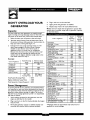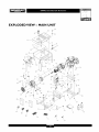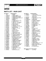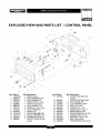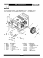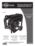
1
Owner's Manual
Generator
Safety Rules....................................
2-3
Wheel kit
Assembly......................................
Know Your Generator .............................
4-5
6
Operation ....................................
Product Specifications.............................
Maintenance ....................................
7-I I
12
12
Storage
Cover
Battery
charge
cables
Spare Spark Plug,Air
Filter, and Oil Filter
Spark PlugWrench
(2) Locking30 Amp plugs
Engineoil
Owner's
manual
Engine manual
If any parts
are missing
or damaged,
call
1-800-270-1408.
Questions?
Storage........................................
12
Troubleshooting .................................
Schematic ......................................
13
14
Wiring Diagram .................................
15
Replacement Parts.............................
Warranty .................................
Help is just a moment
away!
Call: Generac Generator Helpline - 1-800-270-1408
M-F 8-5 CT
Web: www.generac-portables.com
or www.briggsandstratton.com
_This Obeyisall
thesafety
safety
alert symbol.follow
It is usedto
alert you
to potential
messagesthat
this symbol
to avoid
possiblepersonal
injury orinjury
death.hazards.
16-19
Last Page
EQUIPMENT
DESCRIPTION
This generator is an engine-driven, revolving field,
alternating current (AC) generator. It was designed to
supply electrical power for operating compatible electrical
lighting, appliances,tools and motor loads.
This manual contains information for a generator that
operates 120 and/or 240 Volt, single phase,60 Hz devices
that require up to 6,500 watts (6.5 kW) of power that pull
up to 54.2 Amps at 120Volts or 27.1 Amps at 240Volts.
CAUTION!
Do Not exceed the generator's
wattage/amperage capacity.Add up the rated watts of all
devices you are connecting to generator
receptacles at one
time.This total should not be greater than 6,500 watts. See
"Don't Overload the Generator" on page I I.
The generator's revolving field is driven at about 3,600 rpm
by a single-cylinder engine.
SAFETY
RULES
This generator set was designed and manufactured for
specific applications. Do Not attempt to modify the unit or
use it for any application it was not designed for. If you have
any questions about your generator's application, ask your
dealer or consult the factory.
The manufacturer could not possibly anticipate every
circumstance that might involvea hazard. For that reason
warnings in the manual and warnings on tags or decals
affixed to the unit are not all-inclusive. If you intend to
handle, operate or service the unit by a procedure or
method not specifically recommended by the manufacturer,
first make sure that such a procedure or method will not
render this equipment unsafe or pose a threat to you and
others.
Read this manual carefully and become familiar
with your generator set. Know its applications, its
limitations and any hazards involved.
Every effort has been made to ensure that informationin
this manual is accurate and current However, Generac
reserves the right to change,alter or otherwise improve the
product and this document at any time without prior
or other
notice.
_
AUTION!
Not
tamper speeds
with engine
governed
speed.Do
High
operating
are
dangerous and increaserisk of personal injuryor
damageto equipment.The generator supplies
correct rated frequency and voltage only when
running at proper governed speed. Incorrect
frequency and/or voltage can damagesome
connected electrical loads. Operating at excessively
low speeds imposesa heavy load.When adequate
engine power is not availableengine life may be
shortened.
The Emission Control System for this generator is
warranted for standards set by the Environmental
Protection Agency.For warranty informationrefer to the
engine owner's manual.
re
_
ARNING!
must
isolatethe
from
the electricYou
utility
using
approvedgenerator
transfer
equipment if this unit is used for backup power.
Failure to isolate the generator from the
power utility may result in injury or death to
electric utility workers and damage to the
generator due to a backfeed of electrical energy.
Whenever the unit is providing backup power, the
electric utility must be notified.
_
DANGER!
Generator
exhaustgas.
gases
contain in
DEADLY
carbon
monoxide
If breathed
sumcient concentrations,
carbon monoxide
can cause unconsciousness or death. Operate
this equipment outdoors where adequate ventilation
is available.
• The generator produces a very powerful voltage that can
cause serious injury or death by electrocution. Never
touch bare wires or receptacles. Never permit a child or
any unqualified person to operate the generator.
• Never handle any kind of electrical cord or device while
standing in water, while barefoot or while hands or feet
are wet Death or serious injury from electrocution may
result.
• Use a ground fault circuit interrupter (GFCI) in any damp
or highly conductive area (such as metal decking or steel
work).
• Never use worn, bare,frayed or otherwise damaged
electrical cords with the generator. Death, serious injury
and property damagefrom electrical shock may result
• Gasoline is highly FLAMMABLE and its vapors are
EXPLOSIVE. Never allow smoking, open flames,
sparks or heat in the vicinity while handling
gasoline. Avoid spilling gasoline on a hot engine. Comply
with all laws regulating storage and handling of gasoline.
• Never operate the generator:
in rain; in any enclosed compartment; when connected
electrical devices overheat; if electrical output is lost; if
engine or generator sparks; if flame or smoke is observed
while unit is running; if unit vibrates excessively.
GROUNDING
THE
G EN ERATO R
The National Electrical Code requires that the frame and
external electrically conductive parts of this generator be
properly connected to an approved earth ground. Local
electrical codes may also require proper grounding of the
unit. For that purpose, a GROUNDING WING NUT is
provided on the generator end (Figure I).
• Do Not overfitl the fuel tank.Always allow room for fuel
expansion. If tank is overfllled, fuel can overflow
onto a hot engine and cause a FIRE or an
EXPLOSION.
• Never store a generator with fuel in the tank where
gasoline vapors might reach an open flame, spark or pilot
light (as on a furnace, water heater, clothes dryer). FIRE
or an EXPLOSION may result.
• The unit requires an adequate flow of cooling air for its
continued proper operation. Never operate the unit
inside any room or enclosure where the free flow of
cooling air into and out of the unit might be obstructed.
Allow at least2 feet of clearance on all sides of generator,
even while operating unit outdoors, or you could damage
the unit
• Never start, or stop the unit with electrical loads
connected to receptacles with the connected devices
turned ON. Start the engine and let it stabilize before
connecting any electrical loads. Disconnect all electrical
loads before shutting down the generator.
• Do Not insert any object through cooling slots of the
engine.Youcould damagethe unit or injure yourself.
Generally, connecting a No. 12 AWG (American Wire
Gauge) stranded copper wire to the grounding wing nut
and to an earth-driven copper or brass grounding rod
(electrode) provides adequate protection against electrical
shock. Be careful to keep the grounding wire attached after
connecting the stranded copper wire. However, locat codes
may vary widely. Consult with a local electrician for
grounding requirements in your area.
Properly grounding the generator helps prevent electrical
shock if a ground fault condition exists in the generator or
in connected electrical devices. Proper grounding also helps
dissipate static electricity, which often builds up in
ungrounded devices.
Yourgenerator
requires
someassembly
andisreadyfor
useafterit hasbeenproperlyserviced
withthe
recommended
oilandfuel.
If you have any problems with the assembly of your
generator, please call the generator
helpline at
1-800-270-1408.
IMPORTANT: Any attempt to run the unit before it has
been serviced with the recommended oil wilt result in an
engine failure.
INSTALL
WHEEL
KIT
The wheel kit is designed to greatly improve the portability
of your generator.
NOTE:Wheel
kit is not intendedfor over-the-road use.
You will need a socket wrench with I/2" or 13mm sockets
and a needle-nose plier to installthis kit.
Refer to Figure 2 and install the wheel kit as follows:
• Placethe generator on a hard flat surface.
REMOVE G EN ERATOR
FROM CARTON
• Stand at the engine end of the generator and gently tilt
the generator forward, high enough to place wooden
blocks beneath the cradle.This will allow you to add the
wheels.
• Set the carton on a rigid flat surface with "This Side Up"
arrows pointing upward.
• Carefully open the top flaps of the shipping carton.
Review"Cold Weather Operation" on page 9.
• Cut down corners at one end of carton from top to
bottom and lay that side of carton down flat.
• Remove all packing material, carton fillers, etc.
• Slide the axle through the holes in the brackets provided
on the generator cradle.
• Slide one wheel and flat washer on each end of the axle.
Make sure the air inflation valve isoutward. Insert both
retaining pins using the needle-nose plier. Remove the
wooden blocks.
• Attach the vibration mounts to the support leg with
30mm capscrews, washers and lock nuts.
• Remove the generator from the shipping carton.
®
Axle
Wheel
Lock
Washer
_20mm
Capscrew
Retaining Pin
Lock Nut
Capscrew
• Withthewheels
on,youcannowllft upthehandle
end
andattachthesupportlegwith20mmcapscrews
and
locknuts.
• Checkeachfastener
to ensureit issecure
andthetires
areinflatedbetween
15-40PSL
BEFORE STARTING
ENGINE
THE
• Use regular UNLEADED
gasoline with the generator
engine. Do Not use premium gasoline. Do Not mix oil
with gasoline.
• Clean area around fuel fill cap, remove cap.
• Slowly add unleaded regular gasoline to fuel tank. Be
careful not to overfill.Allow
about I/2" of tank space for
fuel expansion (Figure 3).
Tank
1/2" Air
Add Oil
CAUTION!
Any attempt to crank or start the engine
before it has been properly filled with the recommended
oil may result in an engine failure.
To fill your engine with oil:
• Placegenerator on a level surface.
• Followthe oil grade recommendations and oil fill
instructionsgiven in the engine owner's manual.
NOTE: The generator's revolving field rides on a
prelubricated and sealed ball bearing that requires no
additional lubricationfor the life of the bearing.
Add Gasoline
_
ARNING!
Never
tank or
indoors.
Never
fill fuel
tank when
enginefillisfuel
running
hot_Allow
unit to cool for two minutes before refueling. Do
Not light a cigarette or smoke when filling the fuel
tank.
_
WARNING!
Do for
Notfuel
overfill
the fuel tank.
Always
allow room
expansion.
• Install fuel cap and wipe up any spilled gasoline.
IMPORTANT:
It is important to prevent gum deposits
from forming in essential fuel system parts, such as the
carburetor, fuel filter, fuel hose or tank during storage.Also,
experience indicates that alcohol-blended fuels (called
gasohol, ethanol or methanol) can attract moisture, which
leads to separation and formation of acids during storage.
Acidic fuel can damage the fuel system of an engine while
in storage.
To avoid
emptied
on page
products
engine problems, the fuel system should be
before storage of 30 days or longer. See "Storage"
12. Never use engine or carburetor cleaner
in the fuel tank or permanent damage may occur.
KNOWYOUR
GENERATOR
Read this owner's manual and safety rules before operating your generator.
Compare the illustrations with your generator, to familiarize yourself with the locations of various controls
adjustments. Save this manual for future reference.
and
FuelTank
Oit Fill Cap
Circuit Breakers (AC)__,,_
Choke Lever
120 Volt AC, 30 A
Run/Stop Switch
Receptacle
120/240Volt AC,
30 Amp Receptacle
Air Cleaner
12Volt DC, 10Amp
Receptacle
Spark Arrester Muffler
Idle Control Switch
GroundingWing Nut
12 Volt DC, I 0 Amp Receptacle -- Recharge a
discharged 12Volt automotive type battery through this
receptacle.
120 Volt AC, 20 Amp, Duplex Receptacle -- May be
used to supply electrical power for the operation of
120Volt AC, 20 Amp, single phase,60 Hz electrical lighting,
appliance,toot and motor loads.
120 Volt AC, 30 Amp Locking Receptacle -- May be
used to supply electrical power for the operation of
120Volt AC, 30 Amp, single phase,60 Hz electrical lighting,
appliance,toot and motor loads.
120/240 Volt AC, 30 Amp Locking Receptacle -- May
be used to supply electrical power for the operation of
120 and/or 240 Volt AC, 30 Amp, single phase,60 Hz
electrical lighting,appliance, tool and motor loads.
Air Cleaner -- Uses a dry type filter element and foam
pre-cleaner to limit the amount of dirt and dust sucked
into the engine.
Choke Lever -- Used when starting a cold engine.
120Volt AC, 20 Amp
Duplex Receptacle
Circuit Breakers (AC) -- Each receptacle is provided
with a "push to reset" circuit breaker to protect the
generator against electrical overload.
Fuel Tank -- Capacity of seven (7) U.S.gallons.
GroundingWing Nut-- Used for proper grounding of
unit.
Idle Control Switch --With this switch set to ON,
printed circuit board in control panel automatically reduces
engine speed when no toad is connected and increases
engine to proper speed when load is applied. However, be
sure switch is OFF when starting engine.
Oil Fill Cap --Add
oit to engine here.
Recoil starter -- Used to start the engine.
Run/Stop Switch -- Set this switch to "Run" before
using recoil starter. Set switch to "Stop" to switch OFF
engine.
Spark Arrester MufflerExhaust muffler lowers
engine noise and is equipped with a spark arrester screen.
OPERATING
THE
GENERATOR
_
4.
Placethe choke lever in the "Full" choke position
(Figure7).
|
electrical loadsconnected
CAUTION!
Never startAND
or stop
with unit
the with
connected
devices turned ON.
Starting
the Engine
Disconnect all electrical loads from the generator. Follow
these start instructionsteps in numerical order:
I.
Turn the fuel valveto the "On" position (Figure 4).
5.
Grasp the recoil handle and pull slowly until slight
resistance is felt.Then pull rapidly one time only to
start engine.
• If engine starts,proceed to step 7.
• Ifengine fails to start, proceed to step 6.
6.
Move the choke lever to "Half" choke position, and
pull recoil handle twice.
• If engine fails to start, repeat steps 4 thru 6.
7.
2.
Make sure the Idle Control switch is in "Off'
(Figure 5).
position
IDLE
Move choke lever to "Run" position. If engine falters,
move choke lever to "Half" choke position until the
engine runs smoothly and then to "Run" position.
NOTE: If engine still fails to start after 3 pulls, check for
proper oil level in crankcase.This unit is equipped with a
Low Oil Shutdown System.See engine manual.
Refer to the engine
starting
Connecting
3.
Set the Run/Stop switch to "Run" position (Figure 6).
owner's
manual
for complete
instructions.
Electrical
Loads
• Let engine stabilize and warm up for a few minutes after
starting.
• Plug in and turn on the desired 120 and/or 240 VottAC,
single phase,60 Hz electrical loads.
• Do Not connect 240Volt loads to the 120Volt
receptacles.
• Do Not connect 3-phase loads to the generator.
• Do Not connect 50 Hz loads to the generator.
• DO NOT OVERLOADTHE
GENERATOR. See
"Don't Overload the Generator" on page I I.
Stopping the
Your generator has the capability of recharging a discharged
12Volt automotive or utility style storage battery. Do Not
use the unit to charge any 6Volt batteries. Do Not use the
unit to crank an engine having a discharged battery.
Engine
• Unplug all electrical loads from generator panel
receptacles.Never start or stop engine with electrical
devices plugged in and turned on.
• Put the idle control switch in the "Off'
To recharge
position.
• Check fluid level in all battery cells.If necessary,add
ONLY distilled water to cover separators in battery cells.
Do Not use tap water.
• Let engine run at no-load for 30 seconds to stabilize the
internal temperatures of engine and alternator.
• Move run/stop switch to "Stop".
• Close the fuel shut-off valve.
Operating
Automatic
• If the battery isequipped with vent caps,make sure they
are installedand are tight.
• If necessary,clean battery terminals.
Idle Control
• Connect battery charge cable connector plug to panel
receptacle identifiedby the words "12-VOLTS D.C".
This switch is designed to greatly improve fuel economy.
When this switch is turned ON, the engine will only
run at its normal high governed engine speed when an
electrical load is connected.When an electrical load is
removed, the engine will run at a reduced speed. With the
switch off, the engine will run at the normal high engine
speed. Always have the switch off when starting and
stopping the engine.
Charging
_
12 Volt batteries, proceed as follows:
• Connect battery charge cable clamp with red handle to
the positive (+) battery terminal (Figure 8).
12 VOLT D.C.
RECEPTACLE
a Battery
ARNING!
Storage
batteries give
off explosive
hydrogen
gas while
recharging.An
explosive
mixture
will remain around the battery for a long time after
it has been charged.The slightest spark can ignite
the hydrogen and cause an explosion, resulting in
blindness or other serious injury.
÷
POS
NEG
12 VOLT BA'rrERY
_hl
WARNING!
flame, sparks or Do
any Not
otherpermit
sourcesmoking,
of heat open
around a
battery.Wear protective goggles,rubber apron and
rubber gloves when working around a battery.
Battery electrolyte fluid is an extremely caustic
sulfuric acid solution that can cause severe burns. If
• Connect battery chargecable clamp with black handle
to the negative (-) battery terminal (Figure 8).
spill occurs flush area with clear water immediately.
NOTE: Use an automotive hydrometer to test battery
state of charge and condition. Follow the hydrometer
manufacturer's instructions carefully. Generally, a battery is
considered to be at 100%state of charge when specific
gravity of its fluid (as measured by hydrometer) is 1.260or
higher.
• Start engine. Let the engine run while battery recharges.
• When battery has charged, shut down engine
I:|
COLD WEATH
OPERATION
ER
Under certain weather conditions (temperatures below
40°F [4°C] and a high dew point),your generator may
experience icingof the carburetor and/or the crankcase
breather system.
In an emergency, use the original shipping box as a
temporary shelter:
• Cut off all flaps.
• Cut out one of the long sides of the box to expose
exhaust side of unit. Ensure a minimum of two feet
clearance between open side of box and nearest object.
• Cut appropriate slots to access receptacles of unit.
• Start unit, then place box over it.
• Ensure a minimum of two feet clearance between open
side of box and nearest object.
• Face exposed end away from wind and elements.
• Enclosure should hold enough heat created by the
generator to prevent problems.
A
CAUTION!
Never
run unit
indoors.Do
Not
enclose
generator
any more
than
shown.
RECEPTACLES
120 Volt AC, 20 Amp,
Receptacle
Duplex
Each receptacle (Figure 10) is protected against overload
by a 20 Amp push-to-reset circuit breaker.
IMPORTANT: Remove shelter when temperature is
above 40°F [4°C].
For a more permanent shelter, build a structure that will
enclose three sides and the top of the generator:
• Make sure entire muffler-side of generator is exposed.
Note that your generator may appear different from that
shown in Figure 9.
iI
Wind
J
iI
Use each receptacle to operate 120Volt AC, single-phase,
60 Hz electrical loads requiring up to 2,400 watts (2.4 kW)
at 20Amps of current. Use cord sets that are rated for
125Volt AC loads at 20 Amps (or greater).
120/240 Volt AC, 30 Amp,
Receptacle
Locking
Use a NEMA LI4-30 plug with this receptacle. Connect a
4-wire cord set rated for 250VoltAC loads at 30 Amps
(or greater) (Figure I I).You can use the same 4-wire cord
you plan to run a 120Volt load.
_l_
f
Ill
i
120 Volt AC, 30 Amp
Receptacle
Locking
Use a NEMA L5-30 plug with this receptacle. Connect a
3-wire cord set rated for 125Volts AC at 30 Amps to the
plug (Figure 12).
pa_
IlP,Tolp,11loltllHr:T_r_l
Ip,(o]kv_aF.'T o,
.
.
-"
._
m
3-Wire Cord Set
4-Wire Cord Set
i
NEMA
L5-30
Neutral
120V
(Neutral)
Y (Hot)
NEMA L 14-30
|
/_7
Ground (Green)
X (Hot)
Ground (Green)
This receptacle powers 120/240Volt AC, 60 Hz, single
phase loadsrequiring up to 3,600 watts of power at
30 Amps for 120Volts; 6,500 watts of power (6.5 kW) at
30 Amps for 240Volts.The outlet is protected by a 30 Amp
push-to-reset circuit breaker.
_
Hot
AUTION!Although
outletwatts),
is rated
for
120/240Volt
30 Amp (upthis
to 7,200
the
generator is only rated for 6,500 watts. Powering
loads that exceed the wattage/amperage capacity of
the generator can damageit or cause serious
injuries. 240 Volt loadspowered through this outlet
should not exceed 27.1 Amps of current draw.
Use this receptacle to operate 120Volt AC, 60 Hz, single
phase loads requiring up to 3,600 watts (3.6 kW) of power
at 30 Amps.The outlet is protected by a 30 Amp
push-to-reset circuit breaker.
12 Volt
DC,
I 0 Amp
Receptacle
This connector (identified by the legend "I2-VOLT D.C")
supplies 12Volts DC at I 0 Amps through battery charging
cables for recharging 12Volt batteries (Figure 13).See
"Charging a Battery" on page 8.
DON'T OVERLOAD
GENERATOR
YOU R
You must make sure your generator can supply enough
rated (running) and surge (starting) watts for the items you
wilt power at the same time. Follow these simple steps:
I. Select the items you will power at the same time.
3.
Tool or Appliance
Window Air
Conditioner
Refrigerator
Deep Freezer
Television
Light (75 Watts)
Rated (Running)
Watts
1200
Additional Surge
(Starting)Watts
1800
800
50O
50O
75
3075 Total
Running Watts
1600
500
Total Rated (Running)Watts
= 3075
Highest Additional
= 1800
SurgeWatts
Output
Required
LightBulb - 75 watt
Deep Freezer
Sump Pump
Refrigerator/Freezer - 18 Cu. Ft.
Water Well Pump- I/3 HP
Heating/Cooling
Window AC - 10,000 BTU
Window Fan
FurnaceFan Blower - I/2 HP
Kitchen
Microwave Oven - 1000Watt
Coffee Maker
Electric Stove - SingleElement
Hot Plate
Family Room
DVD/CD Player
VCR
Stereo Receiver
Color Television - 27"
1800 Highest
Surge Watts
Personal Computer w/I 7" monitor
Other
Security System
AM/FM Clock Radio
Garage Door Opener - I/2 HP
Electric Water Heater - 40 Gallon
= 4875
Management
DIY/Job Site
Quartz Halogen Work Light
Airless Sprayer - I/3 HP
Reciprocating Saw
Electric Drill - I/2 HP
Circular Saw - 7 I/4"
Miter Saw - I0"
To prolong the life of your generator and attached devices,
it is important to take care when adding electrical loads to
your generator.There should be nothing connected to the
generator outlets before starting it's engine.The correct
and safe way to managegenerator power is to sequentially
add loads as follows:
I.
With nothingconnected to the generator, start the
engine as described in this manual.
2.
Plug in and turn on the first load, preferably the largest
load you have.
3.
Permit the generator output to stabilize (engine runs
smoothly and attached device operates properly.
Rated*
(Running)
Watts
Additional
Surge
(Starting)
Watts
Essentials
Example:
Power
Again, permit the generator to stabilize.
Repeat steps 4 and 5 for each additional load.
Tool or Appliance
Total the rated (running) watts of these items.Thisis
the amount of power your generator must produce to
keep your items running. See Figure 14.
Estimate how many surge (starting) watts you will
need. Surge wattage isthe short burst of power
needed to start electric motor*driven tools or
appliances such as a circular saw or refrigerator.
Becausenot all motors start at the same time, total
surge watts can be estimated by adding only the
item(s) with the highest additional surge watts to the
total rated watts from step 2.
Total Generator
Plug in and turn on the next load.
5.
6.
Never add more loads than the generator capacity.Take
special care to consider surge loads in generator capacity,
as described above.
Capacity
2.
4.
Planer/Jointer - 6"
Table Saw/RadialArm Saw - I0"
Air Compressor - I-I/2 HP
*Wattages listed are approximate
appliance for actual wattage.
II •
75
500
8O0
8O0
1000
5O0
1200
1600
20O0
12O0
3OO
8O0
1800
6O0
1300
1000
1500
1500
25O0
I00
I00
450
50o
80o
18o
30o
480
40O0
1000
600
960
1000
1500
1800
1800
2000
2500
520
1200
960
1000
1500
1800
1800
2000
2500
only. Check toot or
SPECIFICATIONS
Maximum SurgeWatts ................
10,500 watts
Continuous Wattage Capacity ...........
6,500 watts
Power Factor ..............................
1.0
Rated Maximum Continuous AC Load Current:
At 120Volts .......................
At 240 Volts .......................
54.2 Amps
27. I Amps
Phase.................................
Rated Frequency .......................
FuelTank Capacity ...................
I-phase
60 Hertz
7 U.S.gallons
ShippingWeight .........................
200 Ibs.
GENERAL
MAINTENANCE
RECOMMENDATIONS
The Owner/Operator is responsible for making sure that
all periodic maintenance tasks are completed on a timely
basis;that all discrepancies are corrected; and that the unit
is kept clean and properly stored. Never operate a
damaged or defective generator.
Engine
To Clean
internal windings will
resistance of these
the Generator
• Use a damp cloth to wipe exterior surfaces clean.
• A soft bristle brush may be used to loosen caked on dirt
or oil.
• A vacuum cleaner may be used to pick up loose dirt and
debris.
• Low pressure air (not to exceed 25 psi) may be used to
blow away dirt. Inspect cooling air slots and opening on
generator.These openings must be kept clean and
unobstructed.
STO RAG E
The generator should be started at least once every seven
claysand allowed to run at least 30 minutes. If this cannot
be done and you must store the unit for more than
30 days,use the following guidelines to prepare it for
storage.
Maintenance
See engine owner's manual for instructions.
_
and dirt buildup on the generator
eventually decrease the insulation
windings.
contact
with used
motor
oil. Used
oil skin
has
AUTION!
Avoid
prolonged
or motor
repeated
been shown to cause skin cancer in certain
laboratory animals.Thoroughly wash exposed areas
with soap and water.
KEEPOUT OF REACH OF CHILDREN. DON'T
POLLUTE. CONSERVE RESOURCES.RETURN
USED OILTO COLLECTION CENTERS.
Generator
Generator
• Check that cooling air slots and openings on generator
are open and unobstructed.
_
Maintenance
Generator maintenance consists of keeping the unit clean
and dry. Operate and store the unit in a clean dry
environment where it will not be exposed to excessive
dust, dirt, moisture or any corrosive vapors. Cooling air
slots in the generator must not become clogged with
snow, leavesor any other foreign material.
NOTE: Do Not use a garden hose to clean generator.
Water can enter engine fuel system and cause problems. In
addition, if water enters generator through cooling air
slots, some of the water will be retained in voids and
cracks of the rotor and stator winding insulation.Water
Storage
• Clean the generator as outlined in "To Clean the
Generator"
CAUTION!
Do Not place Storage
a storagecovers
cover can
overbea flammable.
hot
generator. Let the unit coot for a sufficient time
before placing the cover on the unit.
Engine
Storage
See engine owner's manual for instructions.
Other
• Do Not
Storage
Tips
store gasoline from one season to another.
• Replace fuel container if it starts to rust. Rust andlor dirt
in fuel can cause problems if it's used with this unit.
• Store in clean and dry area.
TROUBLESHOOTING
Problem
I.
2.
3.
Circuit breaker is open.
Poor connection or defective cord set.
Connected device is bad.
Solution
I. Reset circuit breaker.
2. Check and repair.
3. Connect another device that is in good
condition.
4.
I.
2.
Faultin generator.
Short circuit in a connected load.
Generator is overloaded.
4.
I.
2.
3.
Engine speed is too slow.
3.
Cause
Engine is running,
no AC output is
available.
but
Engine runs good but
bogs down when loads
are connected.
4.
I.
2.
3.
4.
5.
Engine will not start; or
starts and runs rough.
Shorted generator circuit.
Run/Stop switch set to "Stop".
Dirty air cleaner.
Out of gasoline.
Stale gasoline.
Spark plug wire not connected to spark
plug.
6. Bad spark plug.
7. Water in gasoline.
8. Overchoking.
9. Low oil level.
10. Excessivelyrich fuel mixture.
I I. Intake valve stuck open or closed.
12. Engine has lost compression.
Engine shuts down
during operation.
Engine
lacks power.
Engine
falters.
"hunts"
I.
2.
3.
Out of gasoline.
Low oil level.
Fault in engine.
I.
Load is too high.
2.
3.
Dirty air filter.
Engine needs to be serviced.
I.
Choke is opened too soon.
2.
Carburetor
lean.
or
is running too rich or too
4.
I.
Contact Generac service facility.
Disconnect shorted electrical load.
See "Don't Overload the Generator"
on page I I.
Contact Generac Power Systems
service facility.
Contact Generac service facility.
Set switch to "Run".
2.
3.
Clean or replace air cleaner.
Fill fuel tank.
4.
5.
Drain gastank and fill with fresh fuel.
Connect wire to spark plug.
Replace spark plug.
Drain gastank; fill with fresh fuel.
Put choke lever to "Run" position.
Fill crankcase to proper level.
Contact Generac Power Systems
service facility.
II. Contact Generac Power Systems
service facility.
12. Contact Generac Power Systems
service facility.
Fill fuel tank.
I.
2.
Fill crankcase to proper level.
3. Contact Generac Power Systems
service facility.
I. See "Don't Overload the Generator"
on page I I.
2.
Replace air filter.
3. Contact Generac Power Systems
service facility.
I.
Move choke to halfway position till
engine runs smoothly.
2. Contact Generac Power Systems
service facility.
6.
7.
8.
9.
10.
SCHEMATIC
POWER
REGULATOR
BOARD
1
2
POWER
POWER
i i
22
44
G
A
T
E
S
I
G
N
A
L
155
156
22
44
I
YEL
\
/
LOP
i
/
\
LED
I
BLU/WHT
£2
RED
LDP
SWITCH
18
ENG
IGNITION
BATTERY
66
55
13
AUTO
CHARGE
/_
77
55
_55_
I OA
RESET
C B L_
IIA
([_ _+ )_
_tS_
30A
I
30A
WIRING
DIAGRAM
F
20A
1_0/240V
2_
30A
0
GRN
I
GROUND
_ //
SHROUB
Lm
/ /_
_
_
_i_
_4 _
........
I <>
÷
,
ANODE
_o
_.....
,_
_
/
ENGINE
OIL
_o
_L_,'_s_
_<IS_.
=
NUT
LO_
//
ON
BLOCK
N
EXPLODEDVIEW-
MAIN
UNIT
62
_/40
45 /
58
50
55
38
10
77
\
5
8
24
11
31
\
19
6
\
25
i
27
29
16_
25
49
17
26
59
75
24
\\
\\
24
@
67
?
78
\
74
68
\
\
7O
\
71
72
73
79
PARTS LISTItem
I
2
3
4
5
6
7
8
9
10
II
12
13
14
15
16
17
18
19
20
21
22
23
24
25
26
27
28
29
30
31
32
33
34
35
36
37
38
39
40
41
42
Part #
NSP
A92531GS
A92731GS
92247GS
92679GGS
92681AGS
65791GS
96796GS
22129GS
86307GS
25254GS
92609GS
82857GS
40976GS
66476GS
92532GS
22142GS
A7433GS
90239GS
81917GS
B4986GS
83083GS
22531GS
189160GS
66825CGS
74908GS
86308BGS
65795GS
66849AGS
67022GS
84132GS
66386GS
66849GS
B4871GS
22769GS
86494GS
86292GS
77395GS
83465GS
78831BGS
80270GS
78299GS
MAIN
UNIT
Qty Description
2
4
I
2
4
2
2
I
2
I
I
I
I
I
2
12
I
4
4
I
I
I
I
I
2
I
I
I
I
4
4
4
I
I
ENGINE
SUPPORT,Support
SUPPORT,Engine & Muffler
HOUSING, EngineAdapter
ASSEMBLY,Rotor (Inclds Item 7)
ASSEMBLY,Stator
BEARING
WASHER, 22.2 O.D. x 3 Thk
WASHER, M8 Lock
HHMS, 5/16 - 24 x 3/4 SEMS
HHCS, 5/16 - 24 x 9-7/8"
MOUNT, Vibration
MOUNT, Vibration
SCREW, M8 - 1.25 x 20
CAPSCREW, M6 - 1.0 x 12mm
BRACKET,Muffler
SCREW,5/16 - 18 x 3/4"
MUFFLER
GASKET, Muffler
PIN, 4 mm x 10 Rott
DECAL, Ground
SCREEN,Spark Arrester
HHCS, 5/16-18 x I-3/4"
NUT, 5/16-18 Serrated Flange
CARRIER, Rear Bearing
TAPTITE, M5-0.8 x 10
BOLT,M6 -I x 165 mm Stator
RECTIFIER,Battery Charge
TAPTITE, M5-0.8 x 20
GROMMET, Rubber
ASSEMBLY,Power Regulator
ASSEMBLY,Brush Holder
TAPTITE, M5 - 0.8 x 16
COVER, Bearing Carrier
WASHER,#10 Int. Shakeproof
SCREW, M6 -I.0 x 16Wing
HHCS, # I0 Self Driller
NUT, M6 Flange Lock
GROMMET,Tank
HHCS, M6-1.0 x 60, SEMS
VALVE,Tank
BUSHING, PlasticTank
Item Part #
43 B4363GS
44 BI998GS
45
46
47
48
49
50
51
52
53
54
55
56
57
58
59
60
61
62
63
64
65
66
67
68
69
70
71
72
73
74
75
76
77
78
79
Qty Description
CAP, Fuel Gauge
TANK,ASM, 7- Gal (Includes
Items 41 & 42)
SHIELD, Heat
J92039GS
92665GS
INSULATION #2- I/4" Thick
85000GS
CLIP,Insulation
14353621GS
WIRE, Ground
26850GS
2 WASHER, M6 Shakeproof
39287GS
2 HHCS, M8- 1.25x45
92982GS
I DECAL, Danger
189407GS
2 DECAL, Heat Shield
49820GS
2 NUT, M8 Nylok
22145GS
4 WASHER, FIat, 5/16- M8
187104GS
4 WASHER, Nylon
BB5586GS
2 HANDLE
B4605GS
2 GRIP
B4135GS
2 PIN, with Lanyard
AI87024GS
CRADLE
92630GS
ASSEMBLY,Control Panel
189406GS
DECAL, Control Panel
93826GS
DECAL, Start Instructions
SHIELD, Heat
J96068GS
56893GS
CRIMPTITE, 10-24 x I/2"
A8927GS
MANUAL, Engine
189417GS
MANUAL, Owners
43438GS
PLUG, 240V,30A 4-Prong
37806GS
PLUG, 125V,30A 3-Prong
70185GS
OIL FILTER
731 I IGS
ELEMENT,Air Cleaner
65787GS
CABLE, Battery Charge
84882GS
WRENCH, Spark Plug
72347GS
SPARK PLUG
B4767GS
COVER, Storage
B2153GS
6 SCREW,Self Driller, 12-14 x 7/8"
73054GS
I DECAL, Fuel Shut Off
77816GS
2 DECAL, Caution Hot Muffler
20566GS
I DECAL, 1-800
AB3061GS
2 OIL BOTTLES,28 oz.
Optional Accessories Not Included:
84883GS
Cord Wrap
EXPLODED
VIEW
AND
PARTS LIST - CONTROL
PANEL
19
\\\\_
2O
21
19
8
10
10
6
11
6
15
\
16
\
17
26
22
18
8
25
7
2
9
Item
I
2
3
4
5
6
7
8
9
I0
II
12
13
Part #
A92070GS
23897GS
49226GS
91526GS
82538GS
82881GS
43181GS
43182GS
90418GS
75207AGS
75207GS
23365GS
68868GS
Qty
I
4
4
4
I
4
4
4
I
2
2
6
I
Item Part #
14 43437GS
Description
PANEL,Control
FLATWASHER,#10 M5
LOCKWASHER, M5
SCREW, M5-0.8 x 12mm
SWITCH, Idle Control
LOCK WASHER, 7/16"
SCREW,M3-0.5xl0mm
LOCKWASHER, M3
OUTLET, 12V
CIRCUIT BREAKER,30A
CIRCUIT BREAKER,20A
WASHER,#8 Shakeproof
OUTLET, 120Vott, 30Amp
Locking
15
16
17
18
19
20
21
22
23
24
25
26
I|:!
68759GS
43180GS
22264GS
51715GS
64526GS
83970GS
64525GS
87962GS
84335GS
84134GS
B92069GS
84028GS
Qty Description
I OUTLET, 120V/240V,30A
Locking
I OUTLET, 120V,20A Duplex
6 FLATWASHER, M4
6 LOCKWASHER,#8 M4
6 NUT, M4-0.7 Hex
8 SCREW,#6-32 x 3/8"
I BOARD, System Control
4 STAND-OFF, 3/4" Hex
I CIRCUIT BREAKER.12V,10A
I ASSEMBLY,
Wire Harness
I GROMMET, Rubber Conn.
I BOX, Control Panel
I TRANSFORMER, Idle Control
EXPLODED
5
VIEWAND
14
PARTS LIST-WHEEL
KIT
®
11
4
8
Item
I
2
3
4
5
6
7
8
Part #
BB5586GS
B4966GS
93693GGS
87005AGS
39287GS
BI86927GS
27007GS
42909GS
Qty
2
2
I
2
2
I
2
2
Description
HANDLE
WHEEL
AXLE
PIN, Retaining
HHCS, M8- 1.25 x45
LEG,Support
MOUNT, Vibratlon
CAPSCREW, Hex Hd. M8- 1.25
x 30
Item
9
I0
II
12
13
14
15
16
Part #
52858GS
22247GS
39253GS
22145GS
49820GS
187104GS
B4605GS
B4135GS
Qty
4
2
2
6
2
4
2
2
Description
NUT, Lock M8
WASHER,Wheel
CAPSCREW,Hex Hd. - M8 1.25 x 20
WASHER, Flat, 5/16-M8
NUT, M8 Nylok
WASHER, Nylon
GRIP
PIN, with Lanyard
GENERAC
PORTABLE
PRODUCTS,
LLC(hereafter
referred
to astheCOMPANY)
warrants
to theoriginalpurchaser
thatthe
components
initsportable
generator
willbefreefromdefects
inmaterials
or workmanship
for theitemsandperiodsetforth
belowfromthedateoforiginalpurchase.This
warranty
doesnotinclude
thegasoline
engine
whenfurnished
or attached
because
suchengine
iscovered
solelybytheengine
manufacturer's
warranty.
Starting
batteries
arenotwarranted
bytheCOMPANY.The
term"originalpurchaser"
means
thepersonforwhomthegenerator
isoriginally
purchased.This
warranty
isnottransferable
and
applies
onlyto portable
generators
drivenbyanoverhead
valveengine.
Warranty
Schedule:
Consumer*
Engine
Warranted solely by the engine manufacturer
All other parts
2 years (2rid year parts only)
Commercial*
I Year
With the exception of European Community Countries, all units bound for export shall be warranted for One (I) Year in
Consumer applications, and 90 days in Commercial applications as defined below.
*NOTE: For the purpose of this warranty "consumer use" means personal residential household use by original
purchaser.This warranty does not apply to units used for prime power in place of utility. "Commercial
Use" means
all other uses, including rental, construction, commercial and income producing purposes. Once a generator has
experienced commercial use, it shall thereafter be considered a commercial use generator for the purposes of this
waJ'ranty.
During the warranty period, the COMPANY will, at is option, repair or replace any part which, upon examination by the
COMPANY, is found to be defective under normal use and service**.AII transportation costs under warranty, including return to
the factory if necessary,are to be borne by the purchaser and prepaid by the purchaser.This warranty does not cover normal
maintenance and service and does not apply to a generator set, alternator, or parts which have been subjected to improper or
unauthorized installation or alteration, misuse, negligence,accident, overloading, overspeeding,improper maintenance, repair or
storage so as,in the COMPANY's judgement, to adversely affect its performance and reliability.
**NORMAL WEAR: As with all mechanical devices, the generator needs periodic parts service and replacement to
perform well.This warranty will not cover repair when normal wear has exhausted the life of a part or generator.
THERE ISNO OTHER EXPRESS
WARRANTY.THE COMPANY HEREBY DISCLAIMSANY AND ALL IMPLIED
WARRANTIES, INCLUDING BUT NOT LIMITED TO THOSE OF MERCHANTABILITY AND FITNESSFOR A
PARTICULAR PURPOSETOTHE EXTENT PERMITTED BY LAW.THE DURATION OFANY IMPLIEDWARRANTIES
WHICH CANNOT BE DISCLAIMED IS LIMITED TO THETIME PERIODAS SPECIFIEDIN THE EXPRESS
WARRANTY. LIABILITY FOR CONSEQUENTIAL, INCIDENTAL OR SPECIAL DAMAGES UNDER ANY AND ALL
WARRANTIES IS EXCLUDED. THE COMPANY ALSO DISCLAIMS ANY RESPONSIBILITY FOR INCIDENTAL OR
CONSEQUENTIAL DAMAGES,SUCH AS THE LOSSOF TIME OR THE USEOF THE POWER EQUIPMENT, OR ANY
COMMERCIAL LOSS DUETOTHE FAILUREOFTHE EQUIPMENT:AND ANY IMPLIEDWARRANTIES ARE
LIMITED TO THE DURATION OF THIS WRITTEN WARRANTY.
Some states do not allow limitations on how long an impliedwarranty lasts, or the exclusion or limitation of incidentalor
consequential damages,so the above limitations or exclusions may not apply to you.Thls warranty gives you specific legal rights and
you may also have other rights, which vary from state to state.
For service, see your nearest COMPANY authorized warranty service facility or call 1-877-544-0982.Or look on the internet at
www.generac-portables.com.Warranty service can be performed only by a COMPANY authorized service facility.This warranty will
not apply to service at any other facility.At the time of requesting warranty service, evidence of original purchase date must be
presented.