1
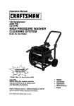
OWNER'S
MANUAL
MODEL
NO.
580.751781
®
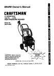
7.8 HORSEPOWER
2500 PSi
3 GPlVi
HiGH PRESSURE WASHER
Mon. - Frl. 8 a.m. to 5 p.m
HOURS:
1
(CST)
CAUTION:
Read and Follow
all Safety Rules
and Instructions
Before Operating
This Equipment
SEARS,
ROEBUCK
Part No, 97019 Revision 1 (8/16195)
o
Assembly
.
Operation
°
Customer
o
Service
°
Repair Parts
and
CO.,
Responsibilities
and Adjustment
Hoffman Estates,
IL
60179
U.S.A.
SAFETY RULES
,_
IT CANNOT CON- .._
TACT
SPARK
PLUG,
TO
PREVENT
ACCIDENTAL
STARTING
WHEN
SETTING
UP,
CAUTION: ALWAYS DISCONNECT SPARK PLUG WIRE AND PLACE WIRE WHERE TRANSPORTING, ,_
ADJUSTING OR MAKING REPAIRS TO YOUR HIGH PRESSURE WASHER.
TRAINING:
•
Engine exhaust gases corrtainDEADLY carbon monoxido gas_ This dangerous gas, if breathed in sufficient
concentraflons,can cause unconsciousnessor even
death_Operate thisequipmentonlyin theopenair where
adequate ventilationis available.
® WARNING: Engine exhaust from this productcontains
chemicals,known,tncertainquantities, to causecancer,
birth defects,or otherreproductiveharm.
e Gasoline is highlyFLAMMABLEand its vaporsare EXPLOSIVE. Do not permitsmoking,openflames, sparks
or heat in the vicinity while handlinggasoline. Avoid
spillinggasoline on a hot engine.Allow unitto cool for 2
mlnutasbefore refueling_Complywithall lawsregulaflng
storageand handlingof gasoline
•
Locatethispressurewasherin areas awayfrom combustible materials,combustiblefumes or dust_
e The highpressureequipmentisdesignedtobe usedwith
Sears authorized parts only. If you use this equipment
withpertsthat do notcomplywithminimum specifications,
the user assumesall risksand liabilities,
•
Some chemicalsor detergentsmay be harmfulif inhaled
oringested,causingseverenausea, fainting or poisoning
The harmful elements may cause propertydamage or
severe injury.
e
Do not allowCHILDREN tooperatethe PresaumWasher
at anytime.
=
PREPARATION:
e Operate englne only at governedspeed Runningthe
engine at excessive speeds increasesthe hazard of
personal injury. Do not tamper with parts which may
increaseor decreasethe governedspeed.
o Do not wear looseclothing,jewelryor anythingthat may
be caught in the starteror otherrotatingparts
e Before starting the Pressure Washer in cold weather,
checkall parts of the equipment and be sure ice has not
formed there
•
e
•
•
o
e
e
e
•
•
e
e
e
e
o
•
e
e
Units with broken or missing parts, or without protective
housingor coversshouldNEVER be operated_
The mufflerand air cleanermustbe installedand in good
conditionbeforeoperatingthe PressureWasher. These
componentsact as sparkarrestors ifthe enginebackfires.
Check the fuel systemfor leaksor signsofdeterioration
suchas chafedor spongyhose, looseor missing clamps
or damagedtank or cap. Correctall defects before operatingthe PressureWasher
e
MAINTENANCE AND STORAGE:
•
Operate and storethis uniton a stable surface.
•
Highpressurehose candevelopleaksfrom wear, kinking,
abuse, etc. Water sprayingfrom a leak is capable of
injectingmaterial intoskin Inspecthoseeachtimebefore
using it Check all hoses for cuts, leaks, abrasionsor
bulgingof cover, or damage or movementof couplings.If
any of theseconditionsexist, replacehose immediately.
Never repairhighpressurehose. Replaceit withanother
hose that meets minimumpressurerating of your pressure washer.
OPERATION:
•
Do not spray flammableHquids.
,= Never aimthe gun at people, animals or plants.
o Never allow any part of the body to come in contact with
the fluid stream. DO NOT come in contact with a fluid
stream created by a leak in the high pressurebese
o High pressure stream of fluid that this equipment can
produce can pieme skin and its underlying tissues, leading to serious injury and possible amputation
I
A
High pressure spray can cause paintchipsor otherparticlesto becomeairborneand flyat high speads,
Always wear eye protectionwhen you usethisequipment
or when you are in the vicinity where the equipment is in
use.
Operate the pressure at no more than the PSI fluid
pressureratedfor yourpressurewasher:
Never movethe machineby pullingon the highpressure
hose. Use the handle providedon the top of the uniL
Alwaysbe certainthespraygun, nozzlas andaccessories
are correctlyattachad.
Never usea spray gunwhichdoes nothave a triggerlock
or triggerguard in place arrdin workingorder.
Use a respiratoror maskwheneverthere isa chansethat
vaporsmay be inhaled Read all instructionswith the
mask soyou are certainthe maskwill providethe necessery protectionagainstinhalingharmfulvapors
High pressurespray may damage fragile itemsincluding
glass_ Do not point spray gun at glass when in the jet
spray mode.
Keep the hose connectedto machineor the spray gun
whilethe systemis pressurized. Disconnectingthe hose
whilethe unit is pressurizedis dangerous.
Hold the spray gun firmly in your hand before you start
the unit. Failureto do so could resultin an injury from a
whippingspray gurr_Do not leave the spray gun unattendedwhilethe machineis running_
The cleaning area should have adequate slopes and
drainageto reducethe possibilityof a fall due toslippery
surfaces.
Keep water spray away from electric wiring or fatal electric
shock may result.
Do not adjust unloader valve to a pressure in excess of
machine rating
Do not secure triggergun in thepull-back(open) position.
Do not by-passany safetydevice on this machine.
Do not leavetriggerclosedfor more than 5 minuteswith
enginerunning This coulddamage the pump
The mufflerand engine heat up during operationand
remain hot immediately after shutting it down. Avoid
contact with a hot muffler or engine or you could be
severely burned,
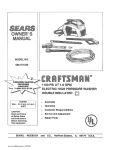
SAFETY PRECAUTIONS,
IT MEANS
"ATTENTIONtH
BELOOK FOR THIS SYMBOL
TO POINT OUT IMPORTANT
COME ALERTH!
YOUR SAFETY IS INVOLVED."
2
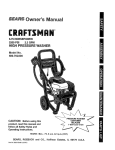
CONGRATULATIONS on your purchase of a Sears Craftsman high pressure washer. It has been designed, engineered and manufactured to give you the best possible
dependability and performance_
PRODUCT
SPECiFICATiONS
Pressure Washer SpeclflcaUona
Should you experience any problem you cannot easily
remedy, please contact your nearest Sears Service Center/Department or call the 1-800 number listed on the front
of this manual We have competent, well-trained technicians and the proper tools to service or repair this uniL
Please read and retain this manual. The instructions will
enable you to assemble and maintain your high pressure
washer properly. Always observe the "SAFETY RULES."
PUMP PRESSURE
Adjustable to 2500 psi
FLOW RATE
3 gpm
DETERGENT MIX
Use undiluted detergent
DETERGENT
Adjustable to 73.1
RATIO
WATER SUPPLY
TEMPERATURE
Not to exceed 140°F
_UCTION HEIGHT
3 FT. maximum
Engine Specifications
RATED HORSEPOWER
7.8
MODEL
NUMBER
580.751781
SERIAL
NUMBER
DISPLACEMENT
_PARK PLUG:
DATE OF
Type:
Set Gap To.
PURCHASE
THE MODEL AND SERIAL NUMBERS WILL BE
FOUND ON A DECAL ATTACHED TO THE PRESSURE WASHER,
YOU SHOULD RECORD BOTH SERIAL NUMBER
AND DATE OF PURCHASE AND KEEP iN A SAFE
PLACE FOR FUTURE REFERENCE
MAINTENANCE
AGREEMENT
Read and observe the safety rules_
•
Follow regular schedule in maintaining, caring for and
using your high pressure washer.
GASOLINE CAPACITY
4 U.S. gallons
OIL (20 oz. capacity)
SAE 30 weight
SOLID STATE IGNITION
AIR GAP
0o0125 inch
NOTE: If you equip the engine ofyourpressure washer with
a spark arrestor muffler, the spark arrestor must be main,tained in effective working order by the owner operator.
RESPONSIBILITIES
®
Champion RC12yc
or equivalent
0.030 inch (0.76mm)
In the State of California a spark arrestor is required by law
(Section 4442 of the California Public Resources Code).
Other states may have similar laws. Federal laws apply on
federal lands,
A Sears Maintenance Agreement is available on this product. Contact your nearest Sears store for details.
CUSTOMER
220cc
You can order a spark arrestor through your Sears Service
Center. See Repair Parts section of engine for part numberso
3
TABLE OF CONTENTS
SAFETY RULES ............................................................
2
CUSTOMER RESPONSIBILITIES
PRODUCT SPECIFICATIONS
3
SERVICE AND ADJUSTMENTS
ACCESSORIES
.......................................
AND A'I-I'ACHEMENTS
CONTENTS OF HARDWARE
...................... 5
PACK .............................
ASSEMBLY ..................................................................
OPERATION ...............................................................
6
7_8
-A-
STORAGE ....................................................................
18
19
WARRANTY
Gun and Wand Assembly .8,9,10
PressureRegulator ........
Hardware Pack ............
6
Low Oil Pressure System ...
-C-
13
-M-
15
15
14
14
Pump .....................
Replace Spark Plug .............
Service Air' Cleaner ..........
Spark Arrestor...............
15
16
16
16
-E17
10
20-26
taL-
11-12
Changing Oil ................
Checking Oil Level ................
General Recommendations ....
Pressure Washer ...............
27
R
6-8
Repair Parts ..........
Customer Responsibilities..,
3
Statement ......................
3
Schedule ....................
14-16
20-26
-H-
-B-
EngineSpeed............
PARTS ..........................................
-p-
High Pressure Hose .......
BeforeStarting.........
...................................................
.................................................................
-G-
Air Cleaner .............
9,16
Assembly
Removingfrom Carton .........
7
Tools Required ...................
7
Set Up .......................
7-8
17
TROUBLESHOOTING
REPLACEMENT
9-13
.......................... 14-16
...................................
Maintenance
Engine .....................
Pump .........................
Nozzle ...................
15
16
17-18
Safety Latch .............
12
Safety Rules ...........
2
Service and Adjustments.
17-18
Storage ................
18
Engine.......................
18
Pressure Washer Pump ........
18
-T-
-OOil, Engine .............
Operation
Detergent Application ........
Stopping...................
To Start Engine .............
To Turn On Washer.........
To Use .......................
-S-
3-11
11
10
12
12
10
Troubleshooting
..........
--Vm
Valve, thermal relief .......
13
W_
Warranty ................
4
19
27
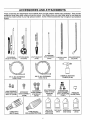
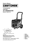
ACCESSORIES
AND ATTACHMENTS
These accessories and attachments were available when the high pressure washer was purchased. They are also
available at most Sears retail outlets and service centers. Most Sears stores can order these items for you when you
provide the model number of your high pressure washer. Some of these accessories may not apply to your pressure
washer,
m
FLOOR/SIDING
ROTATING
BRUSH
KIT (75199)
BRUSH KIT (75190)
UTILITY BRUSH KIT
18" STAINLESS
STEEL EXTENSION
(75189)
(75194)
ELECTRIC TUF_BO
NOZZLE
CHEMICAL INJECTION
FOAMER (74180)
3/8" I.D. 50 ftoEXTENSION
HOSE (75913)
1/4" I.D. 25 ft° EXTENSION
HOSE (75192)
ANGLE ED{TENSION'
KIT {75196)
a!
HIGH PRESSURE
HOSE QUICK CONNECT KIT (75198)
ACCESSORY
QUICK CONNECT
TURBO HEAD
1800 PSI (max,)
(75188)
HIGH PRESSURE
HOSE TO HOSE
COUPUNG
(75191)
ACCESSORY
QUICK CONNECT
STARTER KIT
(75"197)
TURBO NOZZLE
2200 and 2500 PSI (75186)
.5
GARDEN HOSE
QUICKCONNECT
WITH2ADAPTORS
(75187)
MULTI-PUR-
DECK WASH
POSE/HOUSE
WASH (751O0)
(75101)
PRESSURE
GAUGE (75181)
VEHICLF-JBOAT
WASH(75102)
DEGREASER
(75103)
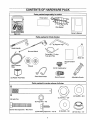
CONTENTS
OF HARDWARE
PACK
Parts packed separately in carton
FF
"_,
-*_-
Pa_s Cadon
Wire Basket
Owner's Manual
Main Unit
Parts packed in Parts Carton
Guide Handle
Gun and Wand
Detergent
Pickup
Tube and Filter
Motor Oil
Nozzle Cleaner
High Pressure
Hose
Kit
Wheels
Oil Fill Cap/Breather
Rear Wand Holder
(2) Rubber Foot Pads
Quick-Connect
Adjustable Nozzle
Parts packed in carton shown full size
(2) Axle Pins
©
(2) Washers - M12
(2) JAM Nuts - 5/8"
(6) Flange Nuts- M8
(6) Hex Head Capscrews - M8 x 45mm
(6) Self-drilling Capscrews - #10-16
(4) Washers - M8
(2) Push Nuts - 1/2"
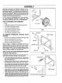
ASSEMBLY
Read these instructions and Operator's Manual in its entirety before you attempt to assemble or operate your new
high pressure washer. Your high pressure washer has, for
the most part, been assembled at the factory, except those
parts left unassembled_ Before you can operate your new
high pressure washer, you must assemble the wheel kit and
properly connect the high pressure hose.
IF YOU HAVE ANY PROBLEMS WITH THE ASSEMBLY
OF YOUR PRESSURE WASHER, PLEASE CALL THE
PRESSURE WASHER HELPLINE AT 1-800-222-3136.
TOOLS
REQUIRED
FOR
ASSEMBLY
,,
Mallet
o
2 adjustable wrenches OR the following wrenches:
o
5/16" (8mm) combination wrench
*
1/2" (13mm) combination wrench
,,
11/16" (18ram) combination wrench
°
7/8" (22mm) combination wrench
o
15/16" (24mm) combination wrench
TO REMOVE
CARTON
PRESSURE
WASHER
HEEL
FIG. 1
QAPSCR_
FROM
o
Remove box for spray gun assembly and support legs
=
Remove accessories box from carton.
°
Remove wire basket (wrapped in plastic)
o
Removeyour
CRADLE FRAME
WASHER
high pressure washer.
Refer to Page 6, "Contents of Hardware Pack" for an
illustrated listing of all items included with your pressure
washer. Become familiar with each piece before assembling pressure washer. Check all contents against illustrations on Page 6. If any parts are missing or damaged, call
Pressure Washer Helpline. at 1-800-222-3136.
/
<
FOOT PAD
HOW
TO SET UP YOUR
PRESSURE
WASHER
TO INSTALL THE WHEEL KIT
Installing the wheel kit requires the tools listed above, the
guide handle and items included in the parts carton.
,,
Prop up the engine end of the main uniL This will allow
you to slip each axle pin into the holes provided on the
side of the base (Fig. 1)
o
Fasten each axle to base with 5/8"-18 JAM nut then place
M12 flat washer over axle. Tighten with 15/16" wrench.
=
Place wheels with valve side of wheel facing outboard
side onto the axles and retain each wheel to its axle by
tapping a push nut onto end of axle with a malleL
o
Insert foot pad into bottom of each support leg (Fig. 2).
=
Using 13mm or 1/2-inch wrench, attach each support
leg to base as shown in Fig. 2 with two M8 x 45mm hex
head capscrews, M8 washers and M8 flange lock nuts.
o
Attach guide handle to cradle (Fig. 3) with two M8-1.25
x 45mm hex head capscraws and two flange nuts.
Attach rear wand holder using 5/16" (8mm) wrench with
#10-16 self-drilling screws to cradle as shown in Fig. 3_
GUIDE HANDLE
CRADLE FRAME
REAR WAND HOLDER - Rest spraygun here
FIG. 3
7
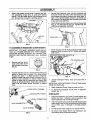
ASSEMBLY
,,
Attach wire basket to bent arms of support legs with
#10 self-drilling screws (Fig_ 4) using 5/16" (6ram)
wrench. The gun holder should be positioned to the
left. Be sure loop of support is pointing upward.
e
Unravel high pressure hose, remove protective cap
from end of hose and check other end of hose to see
that threads are properly covered with teflon tape. If
tape is not properly applied, reapply it so threads are
fully covered. The tape seals the connection from hose
to gun and wand assembly.
Attach fitting with teflon tape to gun and wand assembly
(Fig. 7). You may want to spin gun_ Tighten with 7/8"
wrenches or adjustable wrenches.
SUPPORT
FIG. 4
TO ASSEMBLE
REMAINING
HG. 7
COMPONENTS
Attach the other end of the high pressure hose to high
pressure fitting on pump (Fig. 8) Tighten with adjustable wrench,
IMPORTANT: YOU MUST ASSEMBLE WAND AND ATTACH ALL HOSES BEFORE YOU START ENGiNE,
STARTING
ENGINE WITHOUT ALL HOSES CONNECTED AND WATER SUPPLIED WILL DAMAGE
PUMP.
DETERGENT
PICKUP TUBE AND FILTER
!,
,,
HIGH PRESSURE
HOSE
Remove cap from top of
pump and insert oi/fill
cap included in parts bag
(Fig. 5).
FIGo5
Included with this unit is a Quick-Connect fitting you
attach to Water Inlet on pump. The quick-connect
includes two parts -- a Male Connector factory-installed on water inlet and a Female Connector (Fig 6).
Remove male connector to inspect Intake Supply
Screen in water inlet for cleanliness and inspect Inlet
Screen on female connector, Install male connector to
water inlet and attach female connector to garden
hose.
FIG. 8
*
Pickup Tube and place filter in
IMPORTANT: KEEP DETERGENT
FROM HOT MUFFLER,
INTAKE SUPPLY OPENING
PICKUP TUBE AWAY
,=
Attach Detergent Pickup Tube as shown in Fig. 8_
,,
To attach the adjustable
section, Fig. 11.
nozzle, refer to Operation
CHECKLIST
INTAKE SUPPLY FILTER
_
Unravel Detergent
basket°
o
Check that fasteners you used to install wheels and
handle are tight.
Vibration dudng operation may
loosen fasteners that are not tight enough.
•
Check for proper hose connections (high pressure and
water supply) and for tight connections and that there
are no kinks, cuts, or damage to the high pressure
hose.
=
Provide proper water supply (not to exceed 140°F).
o
Be sure to read "Safety Rules" and "Operation"
tions before using the pressure washen
FEMALE CONNECTOR
MALE CONNE
INLET SCREEN
FIG. 6
8
sec-
OPERATION
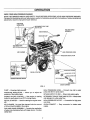
KNOW YOUR HIGH PRESSURE WASHER
READ THIS OWNER'S MANUAL AND SAFETY RULES BEFORE OPERATING YOUR HIGH PRESSURE WASHER.
Compare the illustrations with your high pressure washer to familiarize yourself with the locations of various controls and
adjustments, Save this manual for future reference,
PRESSURE
REGULATOR
AND FILTER
GUN AND WAND
ASSEMBLY
GUIDE HANDLE_
GASOLINE
CAP
HIGH PRESSURE
OUTLET(hoseconnected)
_HIGHPRESSUREHOSE
AIR CLEANER
.PRESSURE
REGULATOR
PUMP
RECOIL STARTER
ENGINE RUN/STOP SWITCH
MALE CONNECToR_MAI-_
G'TOR
INLETSCREEN
QUICK-CONNECT
FIG. 9
HIGH PRESSURE HOSE -- Connect one end to water
pump and other to spray wand°
PUMP -- Develops high pressure,
PRESSURE REGULATOR -pressure of the outlet stream,
Allows you to adjust the
INTAKE SUPPLY FILTER -- Filters inlet water supply.
ENGINE ON-OFF CONTROL -- Sets engine in starting
mode for recoil starter; turns OFF running engine,
DETERGENT PICKUP TUBE AND FILTER-and detergent in outlet water flow.
RECOIL STARTER -ally,
Used for starting the engine manu-
HIGH PRESSURE
sure hose.
OUTLET -- Connection for high pres-
AIR CLEANER - Dry type filter element limits the amount
of dirt and dust that gets in the engine.
QUICK-CONNECT
supply_
--
GUN AND WAND ASSEMBLY-- Controls the application
of water onto cleaning surface with trigger device. Includes
safety latch,
9
Easy connection
Mixes water
for intake water
OPERATION
HOW
TO USE YOUR
WASHER
IF YOU HAVE ANY PROBLEMS OPERATING YOUR
PRESSURE WASHER, PLEASE CALL THE PRESSURE
WASHER HELPLINE AT 1-800-222-3136.
STOPPING YOUR PRESSURE WASHER
o
First, move engine RUN/STOP switch to"OFF" position
(Fig=10).
ADJUSTABLE
NOZZLE
OPTIONAL
FIG. 11
TURBO NOZZLE
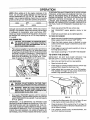
FIG. 12
With the adjustable nozzle you can adjust the spray pattern
to be either high pressure or low pressure, You can also
adjust the spray so it is concentrated in a stream pattern or
expanded into a fan pattern. Use this nozzle to apply
detergenL
o
Push tile nozzle attachment forward when you wish to
adjust the spray to low pressure mode (Fig° 13). Push
the nozzle backward to achieve high pressure,
=
Twisting the nozzle adjusts the spray pattern from a
narrow stream to an expanded stream
FIG. 1O
o
You can also adjust the pressure by turning the pressure
control knob (Fig. 14) to the desired pressure setting.
Turning this knob all the way clockwise produces the highest pressure. Do not unscrew the pressure control valve
more than 3 turns. It will come off.
Simply shutting OFF engine will not release pressure in the system. Pull the trigger on the spray wand
assembly to relieve the pressure in the hose_
NOTE: A small amount of water will squirt out when you
release the pressure.
SPRAY NOZZLES
DECREASE PRESSURE
Your high pressure washer comes equipped with an adjustable nozzle (Fig. 11). You can order a turbo nozzle (Fig
12). Attach either nozzle as shown in Fig 11 and HAND
TIGHTEN the plastic knob.
HOW TO USE ADJUSTABLE
'_
NOZZLE
WARNING: NEVER ADJUST SPRAY PATTERN I
WHEN
SPRAYING,
NEVER
PUT HANDS
IN FRONT
OF SPRAY
NOZZLE
TO ADJUST
SPRAY
PATFIG. 14
TERN.
NOZZLE IN HIGH
PRESSURE MODE
PUSH NOZZLE FORWARD FOR
LOW PRESSURE MODE AND DETERGENT APPLICATION
TWIST NOZZLE TO
EXPAND SPRAY
FIG. 13
]0
TWIST NOZZLE TO NARROW
SPRAY STEAM
OPERATION
APPLYING DETERGENT
NOZZLE
WITH ADJUSTABLE
°
IMPORTANT: USE SOAPS DESIGNED SPECIFICALLY
FOR PRESSURE WASHERS.
HOUSEHOLD DETERGENTS COULD DAMAGE THE PUMP,
To stop flow of detergent, turn knob clockwise or reo
move filter from detergent or set nozzle to high pressure position,
NOTE: Detergents are most effective when applied to a dry
surface.
IMPORTANT:
YOU MUST ATTACH ALL HOSES BEFORE YOU START THE ENGINE STARTING THE ENGINE WITHOUT ALL THE HOSES CONNECTED WILL
DAMAGE THE PUMP_
PRESSURE WASHING/RINSING
WARNING: BE EXTREMELY CAREFUL IF YOU
MUST USE PRESSURE WASHER FROM LADDER,
SCAFFOLDING OR ANY OTHER RELATIVELY UNSTABLE LOCATION. PRESSURE IN A RUNNING
WASHER BUILDS IN THE WAND AS YOU CLIMB.
WHEN YOU PRESS THE TRIGGER, THE RECOIL
FROM THE INITIAL SPRAY COULD FORCE YOU
TO FALL, OR IF YOU ARE TOO CLOSE TO THE
CLEANING SURFACE, HIGH PRESSURE COULD
FORCE YOU OFF CLIMBING APPARATUS.
Pressure washers are useful cleaning tools designed to
clean almost any surface in two easy steps,
o
The first step involves applying an appropriate detergent/solvent solution to penetrate and loosen grime.
The detergent is applied at low pressure to avoid
splashing, overspraying and waste_ Leave the solution
on surface for 3 to 5 minutes to allow solution to work
=
The second step involves cleaning the surface you
have prepared with the pressure washer and then
rinsing it clean.
To apply detergent follow these steps:
QUICK-CONNECT
o
Prepare your detergent solution as required by your
job.
o
Place small filter of the clear, detergent siphoning tube
into the detergent container (Fig. 15).
WATER SUPPLY
FIG. 17
o
Hook up water supply (Fig, 17).
o
Adjust nozzle to select high pressure mode.
NOTE:
mode.
•
FIG. 15
o
Set nozzle to low pressure mode, Detergent is not
siphoned in the high pressure mode (Fig, 13),
o
Start washer and apply detergent to a dry surface.
starting from the bottom and working up. You can
adjust the concentration of detergent by turning the
knob on the detergent injector (Fig. 16).
//
INCREASE
DETERGENT
MIXTURE
!I
Detergent will not flow when in the high pressure
Start washer and work from the top of the surface to
the bottom
NOTE: The high pressure mode is most effective when the
tip of the wand is held between 6 inches to two feet from
the surface being cleaned,
HOW TO USE OPTIONAL TURBO NOZZLE
2-
°
The optional rotating turbo nozzle, in essence, expands
the area of the high pressure stream.
o
You cannot adjust the spray pattern with this nozzle.
=
You cannot apply detergent with this nozzle.
BEFORE
STARTING
THE
ENGINE
To operate the engine you will need the following:
ENGINE OIL
IMPORTANT:
ANY ATTEMPT TO CRANK OR START
THE ENGINE BEFORE IT HAS BEEN PROPERLY SERVICED WITH THE RECOMMENDED OIL RESULTS IN AN
ENGINE FAILURE,
A 20 oz, bottle of SAE 30 weight oil is included in the parts
carton,
FIG. 16
11
OPERATION
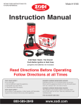
NOTE: When adding oil to the engine crankcase in the
future, use only high quality detergent oil rated with API
service classification SC, SD, SE, SF, SG rated SAE 30
weight. Use no special additives. Select the oil's viscosity
grade according to your expected operating temperature.
I
colder
32°F
5W30
_
warmer
SAE30
TO SEPARATION AND FORMATION OF ACIDS DURING
STORAGE. ACIDIC GAS CAN DAMAGE THE FUEL SYSTEM OF AN ENGINE WHILE IN STORAGE. TO AVOID
ENGINE PROBLEMS, THE FUEL SYSTEM SHOULD BE
EMPTIED
BEFORE
STORAGE
OF 30 DAYS OR
LONGER. SEE "STORAGE" ON PAGE 17. NEVER USE
ENGINE OR CARBURETOR CLEANER PRODUCTS IN
THE FUEL TANK OR PERMANENT DAMAGE MAY OCCUR.
Although multi-viscosity oils (5W30, 10W30, etc.) improve
starting in cold weather, these multi-viscosity oils will result
in increased oil consumption when used above 32°F.
Check your engine oil level more frequently to avoid possible damage from running low on oil. Oil sump capacity is
21 ounces°
•
Clean area around fuel fill cap, remove cap_
o
Add "UNLEADED"
tank_
regular gasoline, slowly, to fuel
o Install fuel cap and wipe up any spilled gasoline
TO TURN ON WASHER
ADD ENGINE OIL:
CAUTION: ANY ATTEMPT TO CRANK OR START
THE ENGINE BEFORE IT HAS BEEN PROPERLY
SERVICED WITH THE RECOMMENDED
OIL RESULTS IN AN ENGINE FAILURE.
Place pressure washer on a level surface and remove
one of yellow Oil Fill Caps (Fig. 18), insert clean funnel
in opening, and add engine oil from the enclosed bottle
until level is at point of overfiowing. Check engine oil
level before starting each time thereafter. If oil level is
below point of overflowing, fill to proper level
Crankcase oil capacity is about 620ml or 21 fluid ounces.
=
Attach one end of a garden hose to a cold water source.
Water supply should not exceed 140°F (55°C)_
=
Check that high pressure hose is attached to pump
outlet and that water supply is attached to pump inlet,
=
Turn ON water
o
Press trigger on gun and wand assembly to force air
from high pressure hose_
=
Start engine according to "TO START THE ENGINE/'
TO START
THE
ENGINE
IMPORTANT: DO NOT RUN PUMP WITHOUT THE
WATER SUPPLY CONNECTED AND TURNED ON
=
Start, store and fuel the unit in a level position.
=
Open fuel shut-off valve_
°
Press trigger on pressure washer wand to relieve high
pressure and/or purge the inlet hose of air.
o
Adjust safety latch on spray gun to the ON position_
This disables the trigger so you cannot inadvertently
actuate a high pressure spray (Fig. 19)_
OIL FILL OPENING
FIG. 18
_o
ADD GASOLINE:
_!_
CAUTION:
DO NOT
OVERFILL
THE EXPANSION.
FUEL TANK.
ALWAYS ALLOW
ROOM
FOR FUEL
FF
WARNING:
FILL WHEN
FUEL TANK
NEVER FILL NEVER
FUEL TANK
ENGINEINDOORS.
IS RUNNING OR HOT. DO NOT LIGHT A CIGARETTE OR
SMOKE WHEN FILLING FUEL TANK.
,,
Use regular UNLEADED gasoline with the pressure
washer engine. Regular leaded gasoline may also be
used if UNLEADED is not available. Fuel tank capacity
is 4 U.S. gallons.
IMPORTANT:
IT IS IMPORTANT TO PREVENT GUM
DEPOSITS FROM FORMING IN ESSENTIAL FUEL SYSTEM PARTS SUCH AS THE CARBURETOR, FUEL FILTER, FUEL HOSE OR TANK DURING STORAGE. ALSO,
EXPERIENCE INDICATES THAT ALCOHOL-BLENDED
FUELS (CALLED GASOHOL OR USING ETHANOL OR
METHANOL) CAN ATTRACT MOISTURE WHICH LEADS
FIG. 19
12
=
Locate the Run/Stop switch (Fig. 20 on Page 13) next
to the engine cylinder head and set it to RUN.
=
Close the choke to FULL position (Fig. 21 on Page 13)
by sliding it to far position in direction indicated by arrow
on air cleaner housing
=
Turn pressure control knob counterclockwise,
turns from maximum pressure.
two
OPERATION
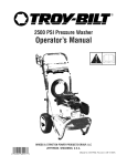
SENSING LOW OIL PRESSURE
If the system senses low oil pressure during operation, the
engine shuts down, As the system shuts down, the low oil
light comes ON However, once the engine has stopped
rotating, this light will go OFF, See Fig, 22 for schematic,
LQV GIL
PRE_;_UR_
L£D
_
"T_J
N
LO_
Ol L
_--
r_v
BLN"
_;HU T DI3WN
FIG. 20
RUN
_NUT
I_L/N
CNG
FULL
FIG. 22
|1
RESTARTING
RUN
If you try to restart the engine within 5 seconds after it shuts
down, the engine may NOT startr The system needs 5 to
10 seconds to reset.
HALF
If you do restart the engine after such a shutdown and
have not corrected the low oil pressure, the engine
runs for about 10 seconds as described above and then
stops.
FIG. 21
,,
Grasp the starter grip and pull slowly until you feel
resistance_ Then pull rapidly one time.
o
When engine starts, move choke lever to "RUN" position. If engine fails to start, move choke lever to "RUN"
position and pull starter rope (maximum 2 pulls)_
SIPHONING
o
If engine fails to start, repeat the previous two steps.
We recommend that you DO NOT siphon your water supply
from sources other than from connecting to household
water supply.
o
Once engine has started, place the Safety Latch on
spray gun to the OFF position.
TIPS
,,
Press trigger on gun andwand assembly_Water should
spray out the nozzle.
,,
o
Adjust nozzle for correct pressure, spray angle. You
can also rum the pressure control knob to the desired
pressure setting.
Initially clean an area and then check the surface for
damage, If no damage is found, you can assume it is
okay to continue cleaning Detergents work best when
applied to dry surface,
=
For most effective cleaning, keep spray nozzle between 8 to 24 inches of cleaning surface°
o
Allow the detergent to soak in between 3-5 minutes
before washing and dnsing
o
For cleaning, start at lower portion of area to be washed
and work upward, using long, even overlapping
strokes.
-
For rinsing, push nozzle sleeve to high pressure and
wait for detergent to clean Start at top of area to be
rinsed, working down with same action as for cleaning.
o
Your pressure washer is ready to use.
IMPORTANT: AN INTERNAL THERMAL RELIEF VALVE
HAS A MAXIMUM TEMPERATURE SEFrING OF 140°F
(60°C). IF YOU RUN THE PUMP FOR 5 MINUTES WITHOUT PRESSING THE TRIGGER ON THE SPRAY GUN,
1/2 TO 1 OUNCE OF WATER IS RELEASED THROUGH
THE VALVE TO COOL THE UNIT. THE SMALL AMOUNT
OF WATER WILL DRIP OUT THE BOTTOM OF PUMP_
LOW OIL PRESSURE
SHUTDOWN
SYSTEM
o
The engine is equipped with a low oil pressure sensor that
shuts down the engine automatically when the oil pressure
drops below 6 psL If the engine shuts down by itself and
the fuel tank has enough gasoline, check engine oil level
Never use garden hose inlet to siphon detergent or
wax.
o
If you get the spray nozzle too close, especially using
high pressure mode, you may damage the cleaning
surface.
INITIAL START'UP
o
A delay built in the shutdown system allows oil pressure to
build during starting. The delay allows the engine to run for
about 10 seconds before sensing oil pressure.
If you have the spray nozzle too far away, the cleaning
will not be as effective_
o
Do not get closer than 6 inches when cleaning automobile tires.
13
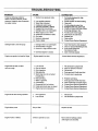
CUSTOMER
MAINTENANCE
SCHEDULE
FILL IN DATES AS YOU COMPLETE
REGULAR SERVICE
RESPONSIBILITIES
HOURLY OPERATING
Before
Each Use
MAINTENANCE TASK
PRESSURE WASHER
Check/cleaninletfilter and screen
SERVICE DATES
INTERVAL
Every25
Hours or
Every50
Hours or
Yearly
Yearly
Every100
Hoursor
Yearly
xv
Check high pressurehose.
x
Check detergenthose.
x
Check gun and wand for leaks.
x
x
Check pumpoil.
x
Purgepumpof air and contanirnents
ENGINE
Check oil level,
x
Change engine oil. _,
x*
Retorque head bolts.
x
Service air cleaner.
X**
CtearVreplacespark plug.
x
Clean spark arrestor screen.
x
Prepare for storage,
Prepare unit for storage if it is to remain idle
longer than 30 days
V Clean if dogged,
Replace if perforated
or torn
_, Change oil after first 8 hours, then after every 50 hours_
" Change sooner when operating und_ heavy load or high arabic nt temperature
GENERAL
** Clean more often under dusty conditions or when alrbome debris is present
RECOMMENDATIONS
PRESSURE
Check High Pressure Hose: High pressure hose can
develop leaks from wear, kinking, abuse. Inspect hose
each time before using iL Check for cuts, leaks, abrasions
or bulging of cover, or damage or movement of couplings.
If an_yof these conditions exist, replace hose immediately_
to
All adjustments in the Service and Adjustments section of
this manual should be made at least once each season.
o
Once a year you should replace the spark plug and
clean or replace the air filter and check the gun and
wand assembly for weal A new spark plug and clean
air filter assure proper fuel-air mixture and help your
ertgine run better and last longer.
BEFORE
&
Check engine oillevel.
=
Check water inlet filter and quick-connect
damage_
Check Detergent Hose: Examine the filter on the detergent hose and clean if clogged_ Hose should fit tightly on
barbed fitting, Examine hose for leaks or tears, Replace
the filter or' hose if either is damaged.
screen for
1,
Check high pressure hose for leaks.
o
Check detergent inlet hose and filter for damage.
,,
Check gun and wand assembly for leaks.
,,
Purge pump of air and contaniments.
DANGER: WATER SPRAYING FROM A LEAK IS CA-]
PABLE OF INJECTING MATERIAL INTO SK]FL NEVER |
REPAIR HIGH PRESSURE HOSE, REPLACE WITH |
HOSETHAT MEETS MINIMUM PRESSURE RATING OF |
YOUR PRESSURE WASHER.
J
EACH USE
o
MAINTENANCE
Check and Clean Inlet Supply Filter and Inlet Screen"
Remove quick-connect and examine inlet screen on trie
female connector and filter on pump inlet fitting. Clean if
either is clogged or replace if either is torn.
The warranty of the high pressure washer does not cover
items that have been subjected to operator abuse or negligence. To receive full value from the warranty, operator
must maintain high pressure washer as instructed in this
manual
Some adjustments will need to be made periodically
properly maintain your high pressure washer.
WASHER
Check Gun and Wand: Examine hose connection to gun
and make sure it is secure. Test trigger by pressing it and
making sure it springs back into place when you release it.
Put safety latch in ON position and test trigger. You should
not be able to press trigger.
Check Pump Oil: Refer to PUMP MAINTENANCE
information.
14
for
CUSTOMER
RESPONSIBILmES
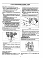
CHANGING ENGINE OIL
Purge Pump of Air and Contanlments:
Change oil after first 8 hours of operation, Change oil
every 50 hours thereafter. If you are using your pressure washer under extremely dirty or dusty conditions,
or in extremely hot weather, change oil more often,
To remove the air from the pump, follow these steps:
o
Set up the pressure washer as described in the ASSEMBLY section and connect the water supply.
,,
Remove the nozzle attachment from the gun.
,,
Pull the trigger on the gun and hold.
,,
To remove the contaniments from the pump, follow these
steps:
=
Set up the pressure washer as described in the ASSEMBLY section, connect the water supply and start
the engine according to instructions in the OPERATION section.
,,
Remove the nozzle attachment from the gun.
,,
Pull the trigger on the gun and hold_
o
When the water supplyis steady and constant, you may
refasten the nozzle attachment and start the pump_
PUMP
A
o
CAUTION:
DISCONNECT
SPARK
PLUG FROM
WIRE
FROM SPARK
PLUG AND KEEP
IT AWAY
SPARK PLUG.
Clean area around oildrain plug, remove plug and drain
oil completely into a suitable container (Fig, 23),
MAINTENANCE
WARNING: DO NOT A'rrEMPT TO DISASSEMBLE I
THE PUMP. WITHOUT THE PROPER TECHNIQUE, I
ATTEMPTING
TO DISASSEMBLE
PUMP MAY I
CAUSE PERSONAL INJURY. FOR SERVICE, CON- I
SULT A SEARS AUTHORIZED SERVICE CENTER
OR CONTACT YOUR PLACE OF PURCHASE.
Pump OIh Change pump oil after first 50 hours of operation. Change pump oil every time you change the engine
oil To change pump oil, follows these steps:
,,
Change oil while engine is still warm from running, as
follows:
,")I L FILL
PLUG
OIL DRAIN PLUG
FIG. 23
o
When eil has drained, install and tighten the oil drain
plug.
=
Remove yellow oil fill plug and insert a clean fill funnel
into plug opening. Fill engine crankcase with recommended oil until oil level is at point of overflowing. Do
not overfill above the point of overflowing. About 21
ounces (620ml) is required. POUR SLOWLY.
o
Install
Place a proper container beneath the pump (Fig. 22).
When engine crankcase is filled to proper level
and tighten oil fill plug.
RETORQUE HEAD BOLTS
OIL LEVEL GAUGE
OIL DRAIN PLUG
After 50 hours of operation, retorque the head bolts for this
GN-Series engine to 4.0 kg/m (29 foot-pounds).
FIG. 22
o
Remove the Oil Drain Plug of pump and drain oil into
the container.
o
When oil has drained completely,
plug.
o
Remove pump's oil fill plug, insert funnel and add
recommendedSAE 80W-90 oil until level reaches full
mark on gauge located on side of the pump_ Capacity
is 5 ounces (150 grams).
,,
Reinstall the pump's oil fill plug.
%
reinstall oil drain
q ..
ENGINE
MAINTENANCE
FIG. 24
CHECKING OIL LEVEL
Oil level should be checked prior to each use or at least
every 5 hours of operation_ Keep oil level maintained
The torque sequence is A, B, C, D, E (star pattern).
Fig 24.
15
See
CUSTOMER
RESPONSIBlUTES
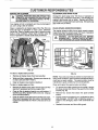
CLEAN/REPLACE
SERVICE AIR CLEANER
I A
COMPLETE AIR CLEANER SYSTEM INSTALLED|
ON THE ENGINE.
RESULT
IN FRE-/1
CAUTION:
NEVER THIS
RUN COULD
THIS UNIT
WITHOUTTHE
MATURE WEAR TO THE ENGINE.
/
Your engine will not run properly and may be damaged if
you run it using a dirty air cleaner.
Clean or replace the air cleaner paper filter (Fig. 25) once
every 25 hours of operation or once a year, whichever'
comes first. Clean or replace more often if operating under
dusty or dirty conditions. Clean foam pre-filter every 25
hours of operation or sooner under dusty conditions.
SPARK PLUG
Change the spark plug every 100 hours of operation or
once each year, whichever comes first. This will help your
engine to start easier and run better° Replace with Champion RC12YC or equivalent type spark plug.. Set spark plug
gap 0.030 inch (0.76mm).
CLEAN SPARK ARRESTOR SCREEN
The engine exhaust muffler has a spark arrestor' screen.
Inspect and clean the screen every 100 hours of operation
or once each year, whichever comes first.
WARNING; LET THE MUFFLER COOL BEFORE l
WORKING ON IT. CONTACT WITH A HOT MUFFLER OR ENGINE CAN CAUSE SEVERE BURNS.
FOAM
COVER
c
FIG. 25
To clean or replace foam pre-filter:
=
Remove air cleaner cover, then foam pre-filter.
,,
Wash pre-filter in soap water. Squeeze pre-cleaner dry
in clean cloth (DO NOT TWIST).
,,
Clean air cleaner cover before installing iL
FIG. 26
NOTE: If you use your pressure washer on any forest-covered, brush-covered or grass-covered unimproved land, it
must have a spark arrestor. The spark arrestor must be
maintained in good condition by the owner/operator.
To clean or replace paper air filter:
Clean and inspect the spark arrestor as follows:
,,
Remove air cleaner cover; then remove foam pre4ilter
(service if necessary) and remove paper filter.
o
,,
CleanairfilterbytappingitgenUyonasolidsurface.
If
the filter is too dirty, replace it with a new one. Dispose
of the old filter properly.
To remove the muffler guard from the muffler, remove
the three screws that connect the guard to the muffler
bracket (Fig. 26).
Q
Remove four screws that attach the spark arrestor
screen.
O
Inspect screen and replace if torn, perforated or other_
wise damaged. DO NOT USE a defective screen° If
screen is not damaged, clean it with commercial solvent
•
Clean air cleaner cover then insert pre-filter into cover.
Next insert new paper filter into cover to hold pre-filter
in place and assemble all of them to the base of the air
cleaner.
Reattach tile screen and the muffler guard,
16
SERVICE AND ADJUSTMENTS
ENGINE SPEED
CAUTION: ENGINE SPEED WAS PROPERLY ADJUSTED AT THE FACTORY AND SHOULD REQUIRE NO ADDITIONAL ADJUSTMENT.
DO NOT
ATTEMPT TO CHANGE ENGINE SPEED. IF YOU
BELIEVE THE ENGINE IS RUNNING TOO FAST OR
TOO SLOW, TAKE YOUR PRESSURE WASHER TO
SEARS AUTHORIZED SERVICE CENTER FOR REPAIR AND ADJUSTMENT.
CHANGING ENGINE
GOVERNED
SPEED WILL VOID ENGINE WARRANTY.
FEELER
ALLEN
0GAUGE
7LOOSEN
JAM NUT
Your pressure washer runs at a constant speed. This
constant operating speed is maintained by a mechanical,
flyweight type, fixed speed govemor_ DO NOT try to adjust
the governed speed setting for the following reasons:
o
High engine speeds are dangerous and increase the
risk of personal injury or damage to equipment
FIGo 27
Low engine speeds impose a heavy load on the engine
when sufficient engine power is not available and may
shorten engine life.
ADJUSTING
VALVE
CLEARANCE
After the first 50 hours of operation, you should adjust the
valve clearance in the engine,
When adjusting valve clearance, engine should be
temperature and piston should be at Top Dead
(TDC) of compression stroke (both valves closed).
clearance is 0_05-0.1mm. Adjust valve clearance
lows:
°
,,
at room
Center
Correct
as fol-
Loosen the rocker arm jam nut. Use an allen wrench
to turn the pivot ball stud while checking clearance
between the rocker arm and the valve stem with a feeler
gauge (Fig. 27).
Tighten jam nut to
65-85 inch-pounds
_-10 N-m).
When valve clearance is correct, hold pivot ball stud
with allen wrench and tighten rocker arm jam nut with
crows fool Tighten am nut to 65_85 inch-pounds
torque. After tightening jam nut, recheck valve clearance to make sure it did not change (Fig, 28).
NOZZLE
FIG. 28
MAINTENANCE
If the nozzle becomes restricted or clogged with foreign
materials, such as dirt, excessive pump pressure may
develop_ A partially clogged nozzle can cause a pulsing
sensation during use. This generally is not a pump related
problem, but rather a clogged or partially restricted nozzle.
If the nozzle becomes clogged or partially restricted, immediately clean the nozzle with the kit included with your
pressure washer by following these instructions:
_,
Shut off the engine and turn off the water supply.
o
=
Separate the wand from the gun_
Remove nozzle from the end of the wand using a 2mm
or 5/64 allen wrench (like the one included in the kit)_
o
Use the wire included in the kit (Fig. 29) or a small paper
clip to free the foreign materials clogging or restricting
the nozzle.
Insert wire into nozzle and turn back and forth to clear obstruction
FIG. 29
17
SERVICE AND ADJUSTMENTS
O
Remove additional debris by back flushing water supply through wand (Fig, 30). Back flush between 30 to
60 seconds. Turn wand to stream spray and move
nozzle from low to high while flushing.
o
Reinstall nozzle into the wand. DO NOT overtighten_
o
Reconnect the wand to the gun
o
Reconnect the water supply, tum on the water, and
start the engine.
o
Test the pressure washer by operating with nozzle in
the high and in the low position.
FIG. 30
STORAGE
AFTER
NOTE: As always, prepare the pressure washer pump as
you would after each use.
EACH USE
Water should not remain in the unit for long periods of time.
Sediments of minerals can deposit on pump parts and
"freeze" pump action. Follow these procedures after every
It is important to prevent gum deposits from forming in
essential fuel system parts such as the carburetor, fuel
filter, fuel hose or tank during storage. Also, experience
indicates that alcohol-blended fuels (called "gasohol" or
using ethanol or methanol) can attract moisture which leads
to separation and formation of acids during storage. Acidic
gas can damage the fuel system of an engine while in
storage_
use:
o
Flush detergent hose by placing the injector filter into
a pail of clear water while running Pressure Washer'
with nozzle in low pressure mode. Flush until you can
see clear water running through the tube
=
Shut off the engine and let it cool, then remove all
hoses.
l
_,
"STOP" POSITION BEFORE YOU CONTINUE. IF I
YOU START THE ENGINE WITHOUT THE PROPER
CAUTION: BE SURE THE THROTTLE LEVER IS IN [
AGEWATERTHESUPPLYPuMP.
CONNECTEDj YOU CAN DAM-
=
Empty the pump of all pumped liquids by pulling recoil
handle about 6 times_ This should remove most of the
liquid in the pump,
o
Coil the high pressure hose and inspect it for damage.
Cuts in the hose or fraying of it could result in leaks and
loss of pressure. Should any damage be found, replace
the hose. DO NOT attempt to repair a damaged hose
and use it. Replace the hose with the genuine Craftsman part.
•
To avoid engine problems, the fuel system should be
emptied before storage of 30 days or longer. Follow these
instructions:
Protect Fuel System: Engines stored over 30 days need
to be protected or drained of fuel to prevent gum deposits
from forming in fuel system or on essential carburetor parts,
=
If you did use "gasohol", run engine until engine stops
from lack of fuel. Make sure you have water supply to
pump inlet connected and turned ON,
Oil Cylinder Bore: Remove spark plug and pour about 1/2
ounce (15mi) of engine oil into the cylinder, Cover spark
plug hole with rag_ Crank slowly to distribute oilo
NOTE; To protect the unit from freezing temperatures, you
can draw windshield washer fluid into the pump by pouring
the washer fluid into a 3-foot section of garden hose connected to the inlet adaptor and pulling the recoil handle
twice.
CAUTIONI
SPRAY
FROMSLOWLY.
SPARK PL.UG I
HOLE
WHENAVOID
CRANKING
ENGINE
,,
Install spark plug. Do not connect spark plug wire.
OTHER
Store in a clean, dry area.
LONG TERM STORAGE
,_
For engine protection use a fuel stabilizer, Mix stabilizer
with fuel in fuel tank and run engine for short time to
circulate stabilizer through carburetor_
Change Oil: While engine is still warm, drain oil from
crankcase. Refill with recommended grade,
Drain water from hose and properly hang it on the wire
support provided on the guide handle.
,,
*
WARNING:
NEVER
ENGINE POORLY
WITH FUELIN
TANK INDOORS
OR STORE
IN ENCLOSED,
VENTILATED AREAS WHERE FUMES MAY REACH AN
OPEN FLAMEp SPARK OR PILOT LIGHT AS ON A
FURNACE, WATER HEATER, CLOTHES DRYER
OR OTHER GAS APPLIANCE.
If you do not plan to use the Pressure Washer for more than
30 days, you must prepare the engine for long term storage.
,,
Do not store gasoline from one season to another.
,,
Replace your gasoline can if your can starts to rust.
Rust and/or dirt in your gasoline will cause problems.
=
If possible, store your unit indoors and cover it to give
pTrotectionfrom dust and dirt. BE SURE TO EMPTY
HE FUEL TANK.
,,
Cover your unit with a suitable protective cover that
does not retain moisture_
IMPORTANT:
NEVER COVER YOUR PRESSURE
WASHER WHILE ENGINE AND EXHAUST AREAS ARE
WARM
]8
TROUBLESHOOTING
PROBLEM
Pump has following problems:
failure to produce pressure, erratic
pressure,chattadng, loss of pressure,
low water volume.
Detergent fails to mix with spray,
Engine runsgood at no-load but "hogs
Engine will not start;or starts
and runs rough
Engine shuts down during operation
CAUSE
CORRECTION
1 Nozzle in low pressure mode.
4. Inadequate water supply
5r Inlet hose is kinked or leaking
6 Clogged inlethose strainer,
7. Detergent line is not submerged.
8. Water supply is over 140°F.
9. Outlet hose is blocked or leaks.
10o Gun leaks,
11, Nozzle is obstructed.
1, Pull nozzlebackwardfor high
pressuremode.
2. Adjust rogulator to desired setttng_
3. Clear inlet
4. Provide adequatawater flow.
5. Straighten inlet hose, patch leak,
6. Check and clean inlet hose strainer,
7. Submerge detergent line,
8, Provide cooler water supply.
9. Clear blocks In outlet hose.
10. Replace gun.
11. Clear nozzle,
12. Pump is faulty.
12. Contact Sears Service Department.
2. Low regulator pressure
3 Water inlet Is blocked.
1. Detergent line is not submerged_
2, Chemical filter is clogged
3 Nozzle is in high pressure mode,
4. Chemical adjuster is closed.
l r Insert chemical line into detergant_
2, Clean or replacefilter/detergent line.
3 Push nozzle forward for
low pressure mode.
4. Open chemical adjustsrr
Engine speed is too slow,
Contact Sears Service Department_
1, Low oillevel
2. Dirtyair cleaner
3_
Out of gasoline,
4. Stale gasoline_
5. Spark plug wire not connected
to sparkplug
6_
Bad spark plug,
Water in gasoline.
8_ Overchoking
9.
Excessivelyrich fuel mixtura_
10. Intake valve stuck open or closed,
11 Engine has lost compression.
1.
2
Out of gasoline,
Low oil level.
1
2.
3.
4.
5.
Fillcrankcaseto proper level
Clean or replaceair cleaner,
Fillfuel tank.
Drain gas tank; fillwith freshfuel,
Connect wire to spark plug.
6_
7_
8,
9.
10,
11.
Replace spark plug.
Drain gas tank; fillwith fresh fuel,
Open choke fully and crank engine.
Contact Sears Service Department.
Contact Sears Service Department.
Contact Sears Service Department.
1.
Fill fuel tank,
2
Fill crankcase to proper level
Engine lacks power,
Dirtyair filter°
Replaceair filter
Engine "hunts" or falters
Choke is opened too soon.
Move choke to halfwayposition
until engine runssmoothly_
]9
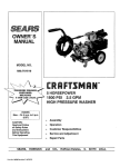
0
I-
o_
z
_a
OTHER iTEM 79
MUST BE LOCATED
OPPOSITE LOWER
CORNER OF CASTING,
Q
"o
-n
m
u)
(/)
nl
3>
(n
..ira
-n
t_
_n
t2
rJ1
37
co
3t
34
:o
m
32
3O
"0
-n
-i
(/)
CRAFTSMAN
ITEM
1
3
4
5
6
7
8
9
10
11
12
13
14
15
16
17
18
19
20
21
22
24
25
26
27
28
29
30
31
32
33
34
35
36
37
38
39
40
41
42
PART NO.
90508
84021
88325
90878
78298
78299
96404
96405
78831B
83465
77395
87840
85000
84687
95203
84508
70644
84346
52858
95635
38750
87985
86292
87836
93728A
94222Q
49808
88521
75402
95189
39287
50190
48476
94135
88688
89712
90300
92535
40976
80314
2500 PSI HIGH PRESSURE
WASHER
DESCRIPTION
7r8 HP Engine(1 mq)
EngineSupport(1 req)
FuelTank (1 req )
Fuel Cap (1 req.)
Tank Valve (1 req.)
PlasticTank Bushing(1 req.)
StartingInstructions Decal (1 raq )
Danger Decal (1 req.)
M6-1.0 x 60mm Capscrew(4 req_)
Tank Grommet(4 req)
M6 Range Lock Nut(4 req.)
Tank Heat Shield
InsulationClip
#2 1/4" thickInsulation(1 req_)
Cradle (1 req.)
45-degreeVibrationMount (4 req)
M8-1,25 x 20mm Screw (3 req,)
M8-1,25 x 35mm Capscrew (2 req)
M8-125 Flange LockNut (19 req )
Pump Support Bracket (1 req)
M6-1_0x 30mm Capscrew (2 req,)
Rear Wand Holder (1 req,)
#10-16 Capscrew (6 req)
Wire Basket (1 req)
Axle Pin (2 req.)
5/8" JAM Nut (2 req,) .
M12 Flat Washer (z reqj
Wheel Assembly (2 req.)
1/2" Push Nut (2 req,)
Support Leg (2 req)
MS-! ,25x 45mm Capssrew (6 req )
5/16 Flat Washer (4 req,)
1" square Cap Plug (2 req,)
Rubber Foot Pad (2 reqr)
MufflerAssembly(1 req.)
Wire MufflerGuard (1 req,)
Muffler Support Bracket (1 req.)
Muffler Support Bracket (1 req.)
M8-1,25 x 20mm Capscrew (2 req,)
Exhaust Gasket (1 req,)
ITEM
43
44
45
46
47
48
49
50
51
52
53
54
55
56
57
58
59
68
62
63
64
65
66
67
68
69
70
71
72
73
74
75
76
77
78
79
81
82
21
580.751781
PART NO.
90299
56893
83083
95194
77584
89634
96168
95567
95587-B
95456
96016
95319C
93790
94944
96542
96865
96430-A
96542
95165
93871
23707
92479
40945
95441
94738
93887
93873
95454
52857
92659
40945
93873
96581F
93723
94197
51767
82580A
48031G
97019
REPAIR
PARTS
DESCRIPTION
M5 x 10ram Screw (9 mq.)
#10-24 CdmptiteScrew (2 req.)
Spark Awester Screen (1 req,)
Guide Handle (1 req_)
Handle Grip(1 req)
3/8 LD, HOSeAssembly (1 req.)
Chemic_ Inlector Hose
Assembly(1 req.)
Gun Assembly (1 req.)
AdjustableNozzle (1 reqo)
Quick-Connect,male (1 req.)
Quick-connect, female 1req)
Pump Head Assembl 1 mq.)
O-ring 2_62x 113.97 req.)
Piston PivotShoe (3 q.)
RollerThrust Beadn 1 req,)
3.0 GPM Axial Cam
'aq,)
Engine Adaptor (1 n
req.)
Roller Thrust Bearin
Engine ShaftAdaptor I req,)
Engine Adaptor Gasket (1 req)
5/16"-24 x 1" Capssrew (4 raq,)
M8 R bbed Lock Washer (4 reqJ
M6-1,0 x 20ram Screw (6 req,)
EngineAdaptor Sleeve (1 req_)
BellevilleWasher(1 mq.)
M16-1,5 JAM Nut (1 req.)
M6 Ribbed Lock Washer (6 req.)
Oil Fill Cap/Breather (1 req,)
M6-1,0 Locking Flange Nut (2 req_)
Replacement NozTJe[red)(1 reqn)
M6-1.0 x 20ram Capscrew (3 req,)
M6 Ribbed Lock Washer (3 req)
Preset Unloader Assembly (1 req,)
Spindle Seat O-ring (.1req,)
Pressure Gauge [optional] (1 req,)
M6-1.0 x 45mm Capseraw (2 t'eq,)
Hose (1 req.)
3/16' Hose Clamp (2 req,)
Owner's Manual [not shown] (1 req)
Drawing No, 97023
@
o_
o
"U
-r
"0
33
m
(n
W A'I'H
R OUT
c:
:o
m
<
I-"
3>
O)
..r
m
1
I
/+1
6
I
5B
7
TAPER
u1
SHAFT
I
!
CO
66
67
L_
#
+
CRAFTSMAN
ITEM
1
2
3
5
6
7
8
9
10
11
12
13
14
15
16
17
18
19
20
21
22
23
24
25
26
27
28
29
30
31
32
33
34
35
36
37
38
39
PART NO.
93871
96430-A
93869
95165
96865
96542
93790
95386
95217
96400
92479
93873
40945
94404
93680
93668
93667
96015
95454
95895
96053
95504
95503
96005
95896
23707
93652
95416
94402
93673
93678
93645
93644
95320
95138
95382
93722
93874
2200 PSI HIGH PRESSURE
WASHER
DESCRIPTION
EngineAdapter Gasket (1 req.)
EngineAdaptor (1 req_)
Thrust Ball Beadng (1 req.)
Engine Adaptor (1 req.)
Axial Cam (1 req )
Thrust Roller Bearing (1 req.)
114 x 119 x 2.6 O-ring (1 req.)
Piston Spring Retainer (3 req)
Piston, D15 S.S. (3 req.)
Piston Return Spring(3 req.)
M8 Ribbed Lock Washer ( 10 req.)
M6 RibbedLock Washer (9 red.)
M6 x 1.0 x 20mm Capscrew (7 req.)
Aluminun Crankcase (1 red.)
Pistion Oil Seal (3 req.)
Pilot Spacer (3 req.)
Seal (3 req.)
Bearing Ring Seal (3 req.)
Oil Fill/Breather(1 reel.)
High Pressure Port Tower (3 red.)
High Pressure Seal [black] (3 req)
Back-up Ring (1 req.)
O-Ring 2.62 x IZ12mm (6 req.}
Valve Check Kit (6 req)
Cheek Valve Seat Support (3 req.)
5/16"-24 x 1" Bolt (4 req.)
Thermal By-pass Spring (1 req_)
By-pass Piston (1 req.)
Spacer Plate (t req )
O-ring 4.5 x 8 x 1.8 (2 red.)
M5-0.8 x 20 Truss Head Bolt (2 req.)
Head Gasket (1 req )
Thermal By-pass Actuator (1 req)
Garden Hose Connector (1 red)
Cylinder Head (1 red.)
Spindle Seat (1 req.)
O-Ring, 0.68 X 0.81 x 0_06(2 req.)
M8-1.25 x 75mm Capscrew (6 req_)
ITEM
40
41
42
43
44
45
46
47
48
49
50
51
52
53
54
55
56
57
58
59
60
61
62
63
64
65
66
67
68
69
71
72
73
74
75
76
77
78
23
580.751651
PART NO.
95373
95367
95372
95378
95377
93788
93787
95376
95374
95375
95384
95364-B
95381-B
96137
93723
95216
95369
95368
95370
95363
96069
95506
95453
57163
95371
95380
94738
93887
95366
95441
94944
94284
93876
95379
93656
93657
95212-B
51767
REPAIR
PARTS
DESCRIPTION
UnloaderAssembly Spindle (1 req)
UnloaderPistonGuide (1 req,)
O-ring 1.78 x 14mm (1 red.)
Chemical Injector Fitting(1 req.)
High PressureOutletAdaptor(1 req)
O-ring 1.78 x 12Atom (1 req.)
O_ring 1.78 x 15.6mm (1 req.)
Spring (1 req)
High Pressure Outlet Piston (1 req.)
O-ring, #2.4 x 4.3 (1 req,)
Pressure Adjust Spring (1 req.)
Pressure Adjust Adaptor with groove
(1 req)
Pressure Adjust Handle [red] (1 req)
1/8" NPT Pipe Plug (1 req_)
"O" Ring 2.6 x 20.2 (1 req.)
Pressure Relief Valve Body (1 raq.)
Back-up O-ring 11 x 12.4 (1 req.)
Unloader Piston (1 req.)
O-ring 1.78 x 7.65 (1 req_)
Spring Support (1 req.!,
Quad-Ring 0.09 x 1.06 (3 req)
Back-up Ring (3 req.)
Sight Gauge Assembly
3/8" NPT Magnetic Plug (1 req.)
PistonSupport O-ring (1 req.)
Chemical Injector Spring (1 req.)
Balieville Washer (1 req.)
M16-1_6JAM Nut (1 req.)
M18 x 1.0 Nut (1 red.)
Engine Adaptor Sleeve (1 req_)
Piston Pivot Shoe (3 req)
"C" Ring Retainer (3 req.)
O-Ring, 0.12 x 0.25 x 06 (1 red.)
Ball (1 req.)
O-Ring 1.78 x 6.07 (1 req.)
Back-up Ring 1.24 x 6.7 {1 req.)
Unloader Assembly (1 req_)
M6-1.0 x 45ram Capscrew (2 req.)
Drawing Noo 97020
34
62
37
58
,|0-
-_
7
28
11
12
49
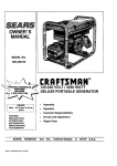
CRAFTSMAN
ITEM
1
2
3
4
5
6
7
8
9
10
11
12
13
14
15
16
17
18
19
20
21
22
24
25
28
27
28
29
30
PART NO,
90508
77182E
81675
81810
83312
90695A
90876
78631
90948
78608A
78601
78602
83015
81671
90051
91846
78609
90947
82774
86962
78604
83502
83782
86037
86384
83781
78643
63503
89739
2200 PSI HIGH PRESSURE
WASHER
DESCRIPTION
580.751781
iTEM
PART NO.
Engine. Taper Shaft (1 req,)
Flywheel Assembly (1 req)
Ignition Coil Assembly (1 req,)
M16-1,5 Hex Nut (1 req)
Conical Washer (1 req!
31
32
33
34
35
78607
78651C
92984
80303
72347
Blower Housing (1 req,)
Carburelor Assembly (1 req)
Carb]Manifold Gasket (1 req)
36
45756
37
66476
HS Intake Manifold (1 req )
Air Cleaner Cover (1 req,)
Air Filter Element (1 req)
Air Filter Pre-Cleaner (1 req.)
Recoil Cup (1 req.)
Recoil Assembly (1 req,)
Manifold/Head Gasket (1 req)
Carburetor/Air Cleaner Gasket (1 req)
38
80316
39
40
42
59635
83504
81668
43
44
46
82981
78653
49813
46
47
48
22097
83512
86753
49
51
56
57
77667
84195
85953
91848
58
61
62
92978
87221A
88758
64
68
69
94820
66311
49811
Bolt - Air Cleaner Cover (2 req)
Breather Hose (1 req,)
4 x 19 Woodruff Key (1 req,)
Govemor Lever Ass (1 req.)
Governor Spring (1 req,)
Governor Ad usting Screw (1 req_)
Idle Control Coil (1 req)
Anti-Lash Extension Spring (1 req)
Governer Rod (1 req.)
Gov, Adjust Bracket (1 req)
Carburetor Mtng, Bolt (2 req)
M5-0,8 Lock Nut (1 req)
Bottom Wrapper (1 req )
2.5
REPAIR
PARTS
QTY.
DESCRIPTION
Air Cleaner Base (1 req,)
BlowerHousingBack Plate (1 req_)
Top Wrapper (1 req.)
Breather Canal Cover (1 req.)
RC12YC Spark Plug
[Champion] (1 req)
M6-1o0x 10mm Bolt (5 req,)
M6-1.0 x 12mm Capscraw (11 req,)
with lock washer (2 req,)
M6-1.0 x 30mm Capscrew
with lock washer (1 req)
No. 8 x 3/8" Plastite Screw (1 req,)
Choke Lever Knob (1 req,)
M6-1.0 x 10mm Capscrew with
lock washer (6 req_)
M6d .0 x 30mm Taptite Bolt (2 req)
Shut-off Switch (1 req)
M6-1.0 Hex Nut (2 req,)
M6 Lock Washer (1 req.)
M8 x 15mm Taptite Bolt (1 req)
Low Oil Indicator LED (1 req)
4 psi Oil Pressure Switch (1 req.)
LOS Engine Decal (1 req,)
Carburetor Wear Washer (1 req.)
Oil Filter Pad Gasket (1 req_)
M6-1,0 x 20rnm Screw (2 req)
LOS Module [optional] (1 req,)
By-pass Adaptor [optional] (1 req,)
Expansion Ptug (1 req,)
JAM-MS-1,25 Hex Nut (1 req,)
M6-12,50,D. Flat Washer (1 req.)
Drawing No, 97064
=o
27
14
28
48
!6
2
8
13
0
42
32
z
"o
33
m
(n
o')
c
3_
m
26
7
47
19
3O
u)
-r
Ill
=0
37
o-,
21
ol
5O
3t
oi
43
co
12
44
45
46
36
13
38
_o
m
"o
39
40
17
5O
"o
2_
-4
car)
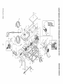
CRAFTSMAN
ITEM
PART
2500 PSI HIGH PRESSURE
NO.
1
2
3
4
5
6
7
8
9
10
11
12
13
14
15
16
17
18
19
21
22
23
24
25
26
76380
76389
88411
81694
72683
88057
76390
83337
78658
76354
89213A
76349
81695
76359
78645
76365
78699B
83335
89096
88055
78691
78367
76362
78692
78606
27
28
76361
89230
WASHER
DESCRIPTION
ITEM
Connector Rod end Cap Assembly (1 req)
Piston Pin (1 req )
Piston Ring Set [standard Size] (1 req)
1/4" Npt Magnetic Pipe Plug (1 req.)
1/8" Npt Pipe Plug (1 req,)
76ram dla. Piston (1 raq )
Piston Pin Retainer (2 req)
Crankshaft Assembly With Gear (1 red )
Governor Arm =R" Pin (1 mq)
Governor Arm (1 req )
Crankcase Sub-assembly (1 req,)
Sleeve Bearing (1 raq,)
Crankshaft Oil Seal (2 req.)
Govemor Gear Assembly (1 req)
Govemor Retainer ["C" Ring] (1 raq )
Governor Spool (1 raq )
12mm Ld, Dowel Sleeve (3 req)
Camshaft Assembly (1 req.)
Crankcase Flange Gasket (1 req)
Cylinder Head Gasket (1 req )
Oil Pressure Spdng Retainer (1 rsq,)
Oil Pressure Spring (1 req)
Oil Pressure Ball (1 req.)
M5 Thread4orming Bolt (1 req)
M6-1.0 x 12mm Screw
and Lock Washer (4 req)
Thrust Washer (1 req )
Flanged Hex Head Capssrew (6 req )
FULL ONE YEAR WARRANTY
580.751781
29
30
31
32
33
34
35
36
37
35
39
40
41
42
43
44
45
46
47
48
49
50
51
52
53
54
57
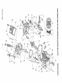
ON CRAFTSMAN
PART
NO.
REPAIR
PARTS
DESCRIPTION
89665A
86293
88401
88590
83152
76381
78659
88404B
90082
90081
88396A
83235
80336
88397
77161
77160
76307
88403
77168
88412
76329
72657
83153
86254
84186
88156
83773F
Gear Cover Sub-assembly (1 req)
Valve Spdng Retainer Valve (2 req.)
Valve Spring (2 req.)
O 10 x20 Dowel Pin (1 req,)
Inner Gerotor (1 req.)
Connecting Rod Bolt (2 req)
Governor Arm Washer (! raq)
Cylinder Head Cssting Assembly
Exhaust Valve (1 raq,)
Intake Valve (1 red,)
Push Rod (2 req.)
Tappet (2 raq )
Oil PIck'.JpAssembly (1 req)
Rocker Cover Gasket (1 req,)
Ball Pivot Stud (2 req)
Rocker Arm (2 req.)
Jam Nut [rocker Arm] (2 req,)
Push Rod Guide Plate (1 req.)
M8 x 52ram Head Bait (5 raq)
Rocker Cover Breather Assembly (1 req)
Oil Fill Plug (1 req)
1/4" Npt Pipe Plug (1 raq )
Outer Gerotor (1 req.)
"o" Ring [178" I,d, x 2,4" Thick] (1 req-)
Wear-valve Spdng Washer
Intake Valve Seal (2 req_)
Decal - Serial Number (1 req )
HIGH PRESSURE
WASHER
For one year from the date of purchase,when thisCraftsman High Pressure Washer is maintained and operated according
to the instructions in the owner's manual, Sears will repair, free of charge, any defect in material and workmanship°
If this washer is used for commercialpurposes, this warrantyapplies for only 90 days from the date of purchase.If this high
pressura washer is used for rental purposes, this warranty applies for only 30 days after date of purchase.
FULL TWO YEAR WARRANTY
ON CRAFTSMAN
ENGINE
For two yearsfrom thedate ofpurchase,whenthisCrafstman engineismaintained and operated accordingto the instructions
in the owner's manual, Sears will repair, free of charge, any defect in material and workmanship.
If the Craftsman Engine is used for commercial or rental purposes, this warranty applies for only one year from the date of
purchase.
This warrantydoes not cover:
,,
Expendable items such as spark plugs and air filters, which become worn during normal use.
,,
Repairs necessary because of operator abuse or negligence, including damage resulting from no water
being supplied to pump or failure to maintain the equipment according to the instnJctions contained in the
owner's manual.
WARRANTY SERVICE IS AVAILABLE BY RETURNING THE HIGH PRESSURE WASHER TO THE NEAREST SEARS
SERVICE CENTER/DEPARTMENT THROUGHOUT THE UNITED STATES.
This warranty gives you specific legal rights and you may also have other rights, which vary from state to state
SEARS, ROEBUCK AND CO., D/817 WA, Hoffman Estates, IL 60179
27
Drawing
No. 88588
®
OWNER'S
MANUAL
7.8 HORSEPOWER
2500 PSi 3.0 GPM
HIGH PRESSURE
WASHER
Each High Pressure Washer has its own model number. Each engine has
its own part number.
MODEL NO.
580.751781
The model number for your pressure washer will be found on a decal
attached to tt_e uniL
The part number for your engine will be found in the parts lisL
IF YOU NEED
All parts listed herein may be ordered through Sears, Roebuck and Co.
Service Centers and most Retail Stores.
REPAIR SERVICE
OR PARTS
WHEN ORDERING
REPAIR
LOWING INFORMATION:
FOR REPAIR SERVICE CALL
THIS TOLL FREE NUMBER
e
PRODUCT--
o
MODEL
e
PART NUMBER
e
PART DESCRIPTION
PARTS,
ALWAYS
HIGH PRESSURE
NUMBER--
GIVE THE FOL-
WASHER
580.751781
1-800-4,_EPAIR
(1-800-473-7247)
FOR REPLACEMENT PARTS
INFORMATION AND ORDERING, CALL THIS TOLL FREE
NUMBER:
1-800-FON-PART
(1-800-366-7278)
SEARS,
ROEBUCK
partNo 97019 Rcvlslon
0 (4/27195)
Your Sears merchandise has added value when you consider that Sears
has service units nationwide staffed with Sears trained technicians_..professional technicians specifically trained on Sears products, having the
parts, tools and the equipment to ensure that we meet our pledge to you,
we service what we sell,
and
CO.,
Hoffman
Estates,
IL
60179
U.S.A.
printed
inU S A