1
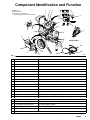
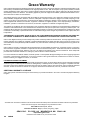
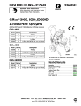
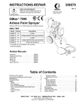
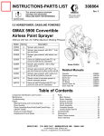
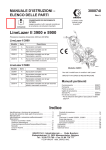
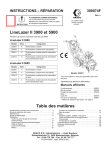
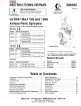
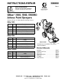
INSTRUCTIONS-REPAIR
308868
Rev. L
KEEP FOR REFERENCE.
Read this and all related manuals for
important warnings and instructions.
First choice when
quality counts.t
INSTRUCTIONS
GMaxr 3900, 5900, 5900HD
Airless Paint Sprayers
3300 psi (227 bar, 22.7 MPa) Maximum Working Pressure
GMax 3900
Model
Series
Description
232610
A
Hi-Boy
232611
A
Hi-Boy with RACt 5 tip, gun and hose
232612
A
Lo-Boy
232613
A
Lo-Boy with RAC 5 tip, gun and hose
233005
A
Hi-Boy with gauge kit
GMax 5900
Model
Series
Description
232620
A
Hi-Boy
232621
A
Hi-Boy with RAC 5 tip, gun and hose
232622
A
Lo-Boy
232623
A
Lo-Boy with RAC 5 tip, gun and hose
233006
A
Hi-Boy with gauge kit
Model 232621
8695A
All models are not available in all countries
PATENTS PENDING
Related Manuals
GMax 5900HD
Model
Series
Description
232627
A
Hi-Boy
232628
A
Hi-Boy with RAC 5 tip, gun and hose
233007
A
Hi-Boy with gauge kit
GRACO INC.
P.O. BOX 1441
Operation . . . . . . . . . . . . . . . . . . . . . . . . . .
Displacement Pump . . . . . . . . . . . . . . . . .
Spray Gun . . . . . . . . . . . . . . . . . . . . . . . . .
Texture Spray Gun . . . . . . . . . . . . . . . . . .
Spray Tip . . . . . . . . . . . . . . . . . . . . . . . . . . .
PC Board . . . . . . . . . . . . . . . . . . . . . . . . . .
Drain Valve Kit . . . . . . . . . . . . . . . . . . . . . .
MINNEAPOLIS, MN
ECOPYRIGHT 1999, GRACO INC.
Graco Inc. is registered to I.S. EN ISO 9001
55440–1441
308867
308798
309091
308491
309055
308919
308961
Table of Contents
Warnings and Cautions . . . . . . . . . . . . . . . . . . . . . . . . . 2
Component Identification and Function . . . . . . . . . . . . 3
Maintenance . . . . . . . . . . . . . . . . . . . . . . . . . . . . . . . . . . . 4
Troubleshooting . . . . . . . . . . . . . . . . . . . . . . . . . . . . . . . . 5
Repair
Bearing Housing & Connecting Rod . . . . . . . . . . . . . 7
Drive Housing . . . . . . . . . . . . . . . . . . . . . . . . . . . . . . . . 8
Pinion Assembly/Rotor/Field/Shaft/Clutch . . . . . . . . 9
Clamp . . . . . . . . . . . . . . . . . . . . . . . . . . . . . . . . . . . . . 10
Clutch Housing . . . . . . . . . . . . . . . . . . . . . . . . . . . . . . 11
Engine . . . . . . . . . . . . . . . . . . . . . . . . . . . . . . . . . . . . . 11
Pressure Control . . . . . . . . . . . . . . . . . . . . . . . . . . . . 13
Displacement Pump . . . . . . . . . . . . . . . . . . . . . . . . .
Parts
GMax 3900 & GMax 5900 Hi-Boy Sprayers . . . . .
Pinion Assembly . . . . . . . . . . . . . . . . . . . . . . . . . . . .
GMax 3900 & GMax 5900 Lo-Boy Sprayers . . . . .
Pressure Control . . . . . . . . . . . . . . . . . . . . . . . . . . . .
Complete Sprayers . . . . . . . . . . . . . . . . . . . . . . . . . .
Dimensions . . . . . . . . . . . . . . . . . . . . . . . . . . . . . . . . . . .
Technical Data . . . . . . . . . . . . . . . . . . . . . . . . . . . . . . . .
Graco Phone Number . . . . . . . . . . . . . . . . . . . . . . . . . .
Graco Warranty . . . . . . . . . . . . . . . . . . . . . . . . . . . . . . .
15
16
18
20
22
24
25
25
25
26
Warnings and Cautions
Warning Symbol
Caution Symbol
WARNING
CAUTION
This symbol alerts you to the possibility of serious
injury or death if you do not follow the instructions.
This symbol alerts you to the possibility of damage to
or destruction of equipment if you do not follow the
instructions.
WARNING
Fire and explosion can occur when spraying or flushing flammable
fluid in an area where air circulation is poor and flammable vapors
can be ignited by an open flame or sparks.
To help prevent a fire and explosion:
DUse outdoors or in an extremely well ventilated area.
DDo not use 1,1,1–trichloroethane, methylene chloride, other
halogenated hydrocarbon solvents or fluids containing such
solvents in pressurized aluminum equipment. Such use could
result in a chemical reaction, with the possibility of explosion.
DRemove, extinguish or unplug all ignition sources;
tape wall switch. Do not smoke in spray area.
DNever fill fuel tank while the engine is running or hot.
DGround Sprayer, object being sprayed, paint and solvent pails.
DHold gun firmly to side of a grounded pail when triggering into pail.
DUse only conductive airless paint hose.
DNever run engine in inclosed area.
Fluid injection is a serious injury! If high pressure fluid pierces
your skin, the injury might look like “just a cut”. But it is a serious
wound! Get immediate medical attention.
To help prevent injection, always:
DEngage trigger safety latch when not spraying.
DPoint gun away from yourself or anyone else.
DRelieve pressure before checking or repairing any leak.
DRelieve pressure when you turn off the sprayer or stop spraying.
DDo not use components rated less than system Maximum
Working Pressure
Never allow children to use this unit. If you are injured using this
equipment, get immediate medical treatment.
2
308868
Component Identification and Function
V
202 Main hose
203 Whip end hose
204 Contractor gun with RAC 5
DripLess tip guard and 517 size SwitchTip
D
C
J
H
E
G
R
K
F
P
S
A
B
U
W
T
Model 232611
202
M
N
X
L
Fig. 1
204
203
8696B
A
Pressure Control Switch
ON/OFF, enables/disables clutch function and pressure control
B
Pressure Adjusting Knob
Controls fluid outlet pressure
C
Air Cleaner*
Filters air entering the carburetor
D
Fuel Tank*
Uses 86 octane unleaded gasoline
E
Muffler*
Reduces noise of internal combustion
F
Spark Plug Cable*
Routes electrical current to spark plug
G
Fuel Shutoff Lever*
On/off lever to regulate fuel flow from gasoline tank to carburetor
H
Choke*
Enriches air/gasoline mixture for cold starting
J
Throttle Lever*
Adjusts engine speed for large or small orifice spray tips
K
Engine Switch*
Enables/disables engine operation
L
Secondary Fluid Outlet
Second hose and spray gun is connected here
M
Pressure Control
Controls clutch cycling to maintain fluid pressure.
N
Primary Fluid Outlet
Hose and spray gun is connected here
P
Engine*
4–cycle gasoline engine
R
Clutch Housing
Transfers power from engine to drive assembly
S
Drive Housing
Transfers power from clutch to displacement pump
T
Displacement Pump
Provides fluid to be sprayed through spray gun
U
Fluid Filter
Filters fluid between source and spray gun
V
Grounding Clamp and Wire
Grounds sprayer system
W
Pail Hanger
Provides a hanger for paint pail
X
Pressure Drain Valve
Relieves fluid pressure when open
*
For more detailed explanations of these controls, refer to the Honda Engines Owner’s Manual; supplied
308868
3
Maintenance
CAUTION
WARNING
INJECTION HAZARD
The system pressure must be manually
relieved to prevent the system from
starting or spraying accidentally. Fluid
under high pressure can be injected through the
skin and cause serious injury. To reduce the risk of
an injury from injection, splashing fluid, or moving
parts, follow the Pressure Relief Procedure
whenever you:
D
D
D
D
are instructed to relieve the pressure,
stop spraying,
check or service any of the system equipment,
or install or clean the spray tip.
Pressure Relief Procedure
1. Lock gun trigger safety.
2. Turn engine ON/OFF switch to OFF.
3. Move pressure control switch to OFF and turn
pressure control knob fully counterclockwise.
4. Unlock trigger safety. Hold metal part of gun firmly
to side of grounded metal pail, and trigger gun to
relieve pressure.
5. Lock gun trigger safety.
6. Open pressure drain valve. Leave valve open until
ready to spray again.
If you suspect that the spray tip or hose is completely
clogged, or that pressure has not been fully relieved
after following the steps above, VERY SLOWLY
loosen tip guard retaining nut or hose end coupling to
relieve pressure gradually, then loosen completely.
Now clear tip or hose.
4
308868
For detailed engine maintenance and specifications,
refer to separate Honda Engines Owner’s Manual,
supplied.
DAILY:
Check engine oil level and fill as necessary.
DAILY:
Check hose for wear and damage.
DAILY:
Check gun safety for proper operation.
DAILY:
tion.
Check pressure drain valve for proper opera-
DAILY:
Check and fill the gas tank.
AFTER THE FIRST 20 HOURS OF OPERATION:
Drain engine oil and refill with clean oil. Reference
Honda Engines Owner’s Manual for correct oil viscosity.
WEEKLY: Remove air filter cover and clean element.
Replace element, if necessary. If operating in an
unusually dusty environment: check filter daily and
replace, if necessary.
Repack connecting rod (22) top needle bearing after
every pump change.
Replacement elements can be purchased from your
local HONDA dealer.
WEEKLY: Check level of TSL in displacement pump
packing nut. Fill nut, if necessary. Keep TSL in nut to
help prevent fluid buildup on piston rod and premature
wear of packings.
AFTER EACH 100 HOURS OF OPERATION:
Change engine oil. Reference Honda Engines Owner’s
Manual for correct oil viscosity.
SPARK PLUG: Use only BPR6ES (NGK) or
W20EPR–U (NIPPONDENSO) plug. Gap plug to
0.028 to 0.031 in. (0.7 to 0.8 mm). Use spark plug
wrench when installing and removing plug.
Troubleshooting
WARNING
INJECTION HAZARD
To reduce risk of serious injury, including fluid injection or splashing in eyes or on skin, or injury from
moving parts, always follow Pressure Relief Procedure Warning, page 4, before checking, adjusting, cleaning or shutting down sprayer.
Check everything in chart before disassembling sprayer.
PROBLEM
CAUSE
SOLUTION
Engine won’t start
Engine switch is OFF
Turn engine switch ON
Engine is out of gas
Refill gas tank. Honda Engines Owner’s Manual.
Engine oil level is low
Try to start engine. Replenish oil, if necessary.
Honda Engines Owner’s Manual.
Spark plug cable is disconnected or damaged
Connect spark plug cable or replace spark
plug
Cold engine
Use choke
Fuel shutoff lever is OFF
Move lever to ON position
Oil is seeping into combustion chamber
Remove spark plug. Pull starter rope 3 or 4
times. Clean or replace spark plug. Try to start
engine. Keep sprayer upright to avoid oil seepage.
Pressure control switch is OFF
Turn pressure control switch ON.
Pressure setting is too low
Turn pressure adjusting knob clockwise to
increase pressure.
Fluid filter (318) is dirty
Clean filter. Page 22.
Tip or tip filter is clogged
Clean tip or tip filter. Manual 309091.
Displacement pump piston rod is stuck due to
dried paint
Repair pump. Manual 308798.
Connecting rod is worn or damaged
Replace connecting rod. Page 7.
Drive housing is worn or damaged
Replace drive housing. Page 8.
Electrical power is not energizing clutch field
Check wiring connections. Page 11.
Engine operates, but displacement pump does not
operate
Reference control board diagnostics. Page 14.
With pressure control switch ON and pressure
turned to MAXIMUM, use a test light to check
for power between clutch terminals on control
board.
Remove black clutch wires from control board
and measure resistance across wires. At 70_
F, the resistance must be between 1.2 ±0.2Ω
(GMax3900); 1.7 ±0.2Ω (GMax 5900); if not,
replace pinion housing.
Have pressure control checked by authorized
Graco dealer.
Clutch is worn, damaged, or incorrectly
positioned
Replace clutch. Page 9.
Pinion assembly is worn or damaged
Repair or replace pinion assembly. Page 9.
308868
5
PROBLEM
CAUSE
SOLUTION
Pump output is low
Strainer (31) is clogged
Clean strainer. Sprayer 232627 strainer is for
use in paint only.
Piston ball (25) is not seating
Service piston ball. Manual 308798.
Piston packings are worn or damaged
Replace packings. Manual 308798.
O-ring (227) in displacement pump is worn or
damaged
Replace o-ring. Manual 308798.
Intake valve ball is not seating properly
Clean intake valve. Manual 308798.
Intake valve ball is packed with material
Clean intake valve. Manual 308798. Do not
leave 232627 sprayer under pressure for more
than 5 minutes when spraying texture and not
actively spraying.
Engine speed is too low
Increase throttle setting. Manual 308867.
Clutch is worn or damaged
Replace clutch. Page 9.
Pressure setting is too low
Increase pressure. Manual 308867.
Fluid filter (318), tip filter or tip is clogged or
dirty
Clean filter. Manual 308867 or 309091.
Large pressure drop in hose with heavy
materials
Use larger diameter hose and/or reduce overall
length of hose. Use of more than 100 ft of 1/4
in. hose significantly reduces performance of
sprayer. Use 3/8 in. hose for optimum performance (50 ft minimum).
Throat packing nut is loose
Remove throat packing nut spacer. Tighten
throat packing nut just enough to stop leakage.
Throat packings are worn or damaged
Replace packings. Manual 308798.
Displacement rod is worn or damaged
Replace rod. Manual 308798.
Air in pump or hose
Check and tighten all fluid connections.
Reprime pump. Manual 308867.
Tip is partially clogged
Clear tip. Manual 309091.
Fluid supply is low or empty
Refill fluid supply. Prime pump. Manual
308867. Check fluid supply often to prevent
running pump dry.
Air in pump or hose
Check and tighten all fluid connections.
Excessive paint leakage into
throat packing nut
Fluid is spitting from gun
Pump is difficult to prime
Reduce engine speed and cycle pump as
slowly as possible during priming.
Intake valve is leaking
Clean intake valve. Be sure ball seat is not
nicked or worn and that ball seats well. Reassemble valve.
Pump packings are worn
Replace pump packings. Manual 308798.
Paint is too thick
Thin the paint according to the supplier’s
recommendations
Engine speed is too high
Decrease throttle setting before priming pump.
Manual 308867.
Clutch squeaks each time
clutch engages
Clutch surfaces are not matched to each other
when new and may cause noise
Clutch surfaces need to wear into each other.
Noise will dissipate after a day of run time.
High engine speed at no
load
Misadjusted throttle setting
Reset throttle to 3600–3800 engine rpm at no
load
Worn engine governor
Replace or service engine governor
6
308868
Bearing Housing and Connecting Rod
NOTE: The item numbers referenced are for the
Hi-Boy models. The Lo-Boy models may have different
item numbers. Use the Hi-Boy item number and part to
find the corresponding Lo-Boy part and item number.
Removal
1.
Relieve pressure; page 4.
2. Fig. 3. Remove screws (14) and front cover (23).
3. For Hi-Boy models; remove spring clip (32) and
drain hose (54). Unscrew suction tube (30) from
pump, hold wrench on pump intake valve (A) to
keep pump from loosening. For Lo-Boy models;
unscrew swivel union (30aa) from pump.
4. Disconnect pump outlet hose (33) from displacement pump outlet nipple (62).
5. Fig. 2. Use screwdriver to push up retaining spring
(26) at top of pump. Push out pin (29).
2. Assemble connecting rod (22) and bearing housing
(21).
3. Clean mating surfaces of bearing and drive housings.
4. Align connecting rod with crank (B) and carefully
align locating pins (F) in drive housing (20) with
holes in bearing housing (21). Push bearing housing onto drive housing or tap into place with plastic
mallet.
CAUTION
DO NOT use bearing housing screws (13) to align
or seat bearing housing with drive housing. Align
these parts with locating pins (F), to avoid premature bearing wear.
5. Install screws (13) and lockwashers (12) on bearing housing. Torque evenly to note 3 value in Fig. 3.
29
6. Refer to Displacement Pump, Installation, page 15.
1
C
E
2
2
D
22
Fig. 2
26
7675B
12, 13
B
3
23
6. Fig. 3. Loosen retaining nut (34). Unscrew and
remove displacement pump (28).
20
7. Remove four screws (13) and lockwashers (12)
from bearing housing (21).
29
8. Pull connecting rod (22) and lightly tap lower rear
of bearing housing (21) with plastic mallet to
loosen from drive housing (20). Pull bearing housing and connecting rod assembly (22) off drive
housing.
14
F 26
33
62
28
34 21
A
9. Inspect crank (B) for excessive wear and replace
parts as needed.
32
54
1
Oil
Installation
2
Pack with bearing grease 114819
1. Evenly lubricate inside of bronze bearing (C) in
bearing housing (21) with high-quality motor oil.
Liberally pack top roller bearing (E), lower bearing
(D) inside connecting rod assembly (22) with
bearing grease.
3
GMax 3900: Torque to 200 in-lb (22.6 Nm)
GMax 5900: Torque to 25 ft-lb (34 Nm)
Fig. 3
30
Model 232610 shown
308868
8697A
7
Drive Housing
Installation
Removal
1.
1. Liberally apply bearing grease (supplied with
replacement gear cluster) to gear cluster (18) and
to areas called out by note 3. Use full 0.62 pint
(0.29 liter) of grease for GMax 3900 and 0.68 pint
(0.32 liter) of grease for GMax 5900.
Relieve pressure; page 4.
2. Fig. 4. Remove bearing housing. Do 1. through 8.
of Bearing Housing and Connecting Rod procedure on page 7.
2. Place bronze colored washer (20g) on shaft protruding from large shaft of drive housing (20).
Note: If replacing a washer with pin holes with a
washer without pin holes, remove guide pins from
housing. Place silver colored washer (20h) on
pinion housing. Align gears and push new drive
housing straight onto pinion housing and locating
pins (B).
3. Remove two screws (81) and lockwashers (17).
4. Remove four screws (10) and lockwashers (17)
from pinion housing (19).
3. Install four screws (10) and lockwashers (17) from
pinion housing (19).
4. Install two screws (81) and lockwashers (17).
5. Lightly tap around drive housing (20) to loosen
drive housing. Pull drive housing straight off pinion
housing. Be prepared to support gear cluster (18),
which may also come out.
2
10
17
5. Fig. 3. Install bearing housing. Do 1. through 6. of
Bearing Housing and Connecting Rod procedure on page 7.
B
19
3
20h
20g
20
17
B
91
81
91
GMax 3900 only
2
Torque to 125 in-lb – GMax 3900
Torque to 200 in-lb – GMax 5900
Apply remaining grease to these areas
3
2
18
Fig. 4
8
1
1
308868
92
91
TI0178A
Pinion Assembly/Rotor/Field/Shaft/Clutch
Removal
6. Fig. 8. Remove retaining ring (19e).
If pinion assembly (19) is not removed from clutch
housing (5), do 1. through 4. Otherwise, start at 5.
1.
7. Tap pinion shaft (19d) out with plastic mallet.
Relieve pressure; page 4.
19e
2. Disconnect field cable (X) from pressure control.
19d
X
8703A
Fig. 8
Bottom View
8699A
Fig. 5
3. Fig. 6. Remove five screws (10) and lockwashers
(17) and pinion assembly (19).
8. Fig.9. Use an impact wrench or wedge something
between armature (4a) and clutch housing to hold
engine shaft during removal.
9. Remove four screws (16) and lockwashers (17).
10. Remove armature (4a).
10
17
19
4a
17
16
10
17
Fig. 6
8704A
Fig. 9
8700A
4. Fig. 7. Place pinion assembly (19) on bench with
rotor side up.
5. Remove four screws (72) and lockwashers (17).
Install two screws in threaded holes (E) in rotor.
Alternately tighten screws until rotor comes off.
72
17
E
Fig. 7
8701A
308868
9
Pinion Assembly/Rotor/Field/Shaft/Clutch
Installation
1. Fig. 10. Lay two stacks of two dimes on smooth
bench surface.
7. Install retaining ring (Z) with beveled side facing
field (Y).
2. Lay armature (4a) on two stacks of dimes.
3. Press center of clutch down on bench surface.
4a
6. Fig. 8. Tap pinion shaft (A) in with plastic mallet.
8. Fig. 7. Place pinion assembly on bench with rotor
side up.
0.12 ±.01 in. (3.0 ±.25 mm)
8705A
Fig. 10
9. Apply locktite to screws. Install four screws (16)
and lockwashers (17). Alternately torque screws
to 125 in-lb until rotor is secure. Use threaded
holes to hold rotor.
10. Fig. 6. Install pinion assembly (19) with five screws
(10) and lockwashers (17).
4. Install armature (4a) on engine drive shaft.
5. Install four screws (16) and lockwashers (17) with
torque of 125 in-lb.
11. Fig. 5. Connect field cable (X) to pressure control.
Clamp
Removal
1
Face of clutch housing
1. Fig. 11. Loosen two screws (16) on clamp (8),
2
1.550 ±.010 in. (39.37 ±.25 mm); GMax 3900
1.812 ±.010 in. (46.02 ±.25 mm); GMax 5900
3
Torque to 125 ±.10 in-lb (14 ±1.1 Nm)
4
Chamfer this side
2. Push screwdriver into slot in clamp (8) and remove
clamp.
1
Installation
5
1. Fig. 11. Install engine shaft key (7).
2
2. Tap clamp (8) on engine shaft (A) with plastic
mallet.
3. Press clamp (8) onto engine shaft (A). Maintain
dimension shown note 2 in Fig. 11. Chamfer must
face engine.
Check dimension: Place rigid, straight steel bar (B)
across face of clutch housing (5). Use accurate
measuring device to measure distance between
bar and face of clamp. Adjust clamp as necessary.
Torque two screws (16) to 125 ±10 in-lb (14 ±1.1
Nm).
10
308868
8
7
4
B
16 3
Fig. 11
A
03483
Clutch Housing
Removal
1. Fig. 12. Remove four capscrews (75) and lockwashers (77) which hold clutch housing (5) to
engine.
5
7
2. Remove screw (15) from under mounting plate (D).
3. Remove engine key (7).
4. Pull off clutch housing (5).
Installation
77
1. Fig. 12. Push on clutch housing (5).
75
2. Install four capscrews (75) and lockwashers (77)
and secure clutch housing (5) to engine. Torque to
200 in-lb (22.6 NSm).
D
15
3. Install capscrew (15) from beneath mounting
plate (D). Torque to 26 ft-lb (35.2 NSm).
Fig. 12
8708A
Engine
Removal
1. Remove Pinion Assembly/Rotor/Field/Pinion/
Clutch, Clamp and Clutch Housing, as instructed on pages 9, 10 and 11.
2. Fig. 13. Disconnect all necessary wiring.
3. Fig. 14. Remove two locknuts (71) and screws
(70) from base of engine.
4. Lift engine carefully and place on work bench.
NOTE: All service to the engine must be performed by
an authorized HONDA dealer.
70
71
1
3
87
Green
71
Fig. 14
8710A
Installation
1. Lift engine carefully and place on cart.
2. Fig. 14. Install two screws (70) in base of engine
and secure with locknuts (71). Torque to 200 in-lb
(22.6 NSm).
3
Fig. 13
2
2
8709A
1
To the field
2
To the engine
3
GMax 5900s only
3. Fig. 13. Connect all necessary wiring.
4. Install Pinion Assembly/Rotor/Field/Pinion/
Clutch, Clamp and Clutch Housing, as
instructed on pages 9 and 10 and 11.
308868
11
On/Off Switch
Removal
Installation
1.
1. Install new ON/OFF switch (309) so tabs of switch
snap into place on inside of pressure control
housing.
Relieve pressure; page 4.
2. Fig. 15. Remove five screws (307) and
cover (322).
3. Disconnect two wires (A) from ON/OFF
switch (309).
4. Press in on two retaining tabs on each side of
ON/OFF switch (309) and remove switch.
3. Install pressure control cover (322) with five
screws (307).
313
310
1
309
2. Connect two wires (A) to ON/OFF switch.
A
315
319
318a
302
303
307
D
322
318z
318aa
E
Fig. 15
12
308868
1
Locate switch terminals as shown
8711A
Pressure Control
Control Board
Installation
Removal
1.
Relieve pressure; page 4.
2. Fig. 15. Remove five screws (307) and
cover (322).
When installing replacement control board, follow
instructions with control board to set model type.
1. Fig. 15. Install green ground wire and control
board (302) with five screws (303).
3. Fig. 22. Disconnect at control board (302):
D Four clutch leads: two violet and two black.
2. Fig. 22. Connect to control board (302):
D Lead (D) from potentiometer.
D Two red leads (A) to ON/OFF switch (309).
D Lead (E) from transducer.
D Lead (E) to transducer.
D Two red leads (A) to ON/OFF switch (309).
D Lead (D) to potentiometer.
4. Fig. 15. Remove five screws (303), green ground
wire and control board (302).
D Four clutch leads: two violet and two black.
3. Fig. 15. Install cover (322) with five screws (307).
Pressure Control Transducer
5. Remove pressure control transducer (318z) and
packing o-ring (318aa) from filter housing (318a).
Removal
1.
Relieve pressure; page 4.
2. Fig. 15. Remove five screws (307) and
cover (322).
3. Disconnect lead (E) from control board (302).
4. Remove three screws (319) and fluid filter (318)
from control plate (301). Carefully pull transducer
connector through rubber grommet (315).
Installation
1. Fig. 15. Install packing o-ring (318aa) and pressure control transducer (318z) in filter
housing (318a). Torque to 30–35 ft-lb.
2. Carefully feed transducer connector through
rubber grommet (315). Install fluid filter (318) on
control plate (301) with three screws (319).
3. Connect lead (E) to motor control board (302).
4. Install cover (322) with five screws (307).
Pressure Adjust Potentiometer
Removal
1.
Installation
1. Install seal (311) on potentiometer (310).
Relieve pressure; page 4.
2. Fig. 15. Remove five screws (307) and
cover (322).
3. Disconnect lead (D) from control board (302).
2. Fig. 15. Install pressure adjust potentiometer
(310), shaft nut, lockwasher (310) and potentiometer knob (313).
a. Turn potentiometer shaft (310) clockwise to
internal stop. Assemble potentiometer knob
(313) to strike pin on plate (312).
b. After adjustment of step a., tighten both set
screws in knob 1/4 to 3/8 turn after contact
with shaft.
4. Loosen set screws on potentiometer knob (313)
and remove knob, shaft nut, lockwasher (310) and
pressure adjust potentiometer (310).
3. Connect lead (D) to control board (302).
5. Remove seal (311) from potentiometer (310).
4. Install cover (322) with five screws (307).
308868
13
Pressure Control
Control Board Diagnostics
1. Fig. 15. Remove five screws (307) and
cover (322).
2. Start sprayer.
3. Turn ON/OFF switch ON.
4. Observe LED operation and reference following
table:
LED
BLINKS
SPRAYER OPERATION
Two times
repeatedly
Sprayer shuts down and LED contin- Run away pressure.
Pressure greater than
ues to blink two times repeatedly
4500 psi (310 bar, 31
MPa).
1. Check pressure transducer connection at control board
2. Replace pressure transducer
3. Replace control board
Three
times repeatedly
Sprayer shuts down and LED contin- Pressure transducer is
faulty or missing
ues to blink three times repeatedly
1. Check pressure transducer connection at control board
2. Replace pressure transducer
3. Replace control board
Four times
repeatedly
Sprayer shuts down and LED contin- Generator voltage is
low
ues to blink four times repeatedly
1. Increase engine throttle
2. Check wiring connections
3. Service Honda engine alternator
Five times
repeatedly
Sprayer shuts down and LED contin- High clutch current
ues to blink five times repeatedly
1. Check clutch 5-pin bulkhead connector. Clean contacts.
2. Measure 1.2 ±0.2Ω (GMax 3900);
1.7 ±0.2Ω (GMax 5900) across
clutch field at 70_F
3. Replace clutch field assembly
Six times
repeatedly
Sprayer shuts down and LED contin- High clutch temperature 1. If clutch is new, let sprayer cool
ues to blink six times repeatedly
down and then restart
2. Inspect clutch. Replace clutch if
there is excessive wear.
3. Remove pump pin, separate pinion housing from clutch housing.
Rotate rotor clockwise to check
for excessive drag.
14
308868
INDICATES
WHAT TO DO
Displacement Pump
Removal
1. Flush pump.
5. Fig. 17. Use screwdriver: push retaining spring up
and push out pin (29).
29
2.
Relieve pressure; page 4.
3. Fig. 16. Cycle pump with piston rod (222) in its
lowest position.
4. Fig. 16. Remove suction tube (30) and hose (33).
7675B
Fig. 17
6. Fig. 18. Loosen locknut by hitting firmly with a
20 oz (maximum) hammer. Unscrew pump.
222
33
30
Fig. 16
7672B
7673B
Fig. 18
Repair
See manual 308798 for pump repair instructions.
Installation
WARNING
If pin works loose, parts could break off due to
force of pumping action. Parts could project
through the air and result in serious injury or property damage. Make sure pin and retaining spring
are properly installed.
2. Fig. 17. Push pin (29) into hole. And push retaining
spring into groove all the way around connecting
rod.
Fig. 20. Screw jam nut down onto pump until nut
stops. Screw pump up into bearing housing until it is
stopped by jam nut. Back off pump and jam nut to
align pump outlet to back. Tighten jam nut by hand,
then tap 1/8 to 1/4 turn with a 20 oz (maximum) hammer to approximately 75" 5 ft–lb (102 Nm).
CAUTION
If the pump locknut loosens during operation, the
threads of the bearing housing will be damaged.
Make sure locknut is properly tightened.
1. Fig. 19. Pull piston rod out 1.5 in. Screw in pump
until holes in bearing cross link and piston rod
align.
Fig. 20
7673B
Fig. 21. Fill packing nut with Graco TSL until fluid flows
onto the top of seal.
1.5 in.
Fig. 19
7676B
7677B
Fig. 21
308868
15
Parts Drawing – GMax 3900, 5900, 5900HD Hi-Boy Sprayers
Models 232610, 232620 and 232627
DETAIL A
Ref 11
40
45
37
38
39
1
Label
2
See page 18 for the parts.
3
See manual 308798
for the parts.
4
See page 22 for the parts.
5
Used on GMax 5900, 5900HD
6
Used on GMax 3900
7
93 and 94 used on GMax 5900HD
8
Used on GMax 3900, 5900
5
8699A
2
19
Ref 35
2
20
91
2
17
81
22
4b
3
12
2
6
56
91
1
18
13
23
21
92
11
(Ref)
2
20g
17
4
61 (Ref)
20h
72
78
Bottom View
6
9
87
55
10
17
68
26
29
5
36
7
47
33
8
DETAIL A
17
49
35
34
62
16
4a
3
67
14
28
54
32
70
61
77
73
71
80
90
30
8
31
17
16
15
71
33(Ref)
51
53
41
5
44
42
43
16
308868
50
4
7
93 53
88
89
94
7
54(Ref)
8713B
Parts List – GMax 3900, 5900, 5900HD Hi-Boy Sprayers
Models 232610, 232620 and 232627*
Ref
No.
Part No.
1
2
3
4
108879
114530
113084
192014
241109
241113
4a
4b
5
193540
193531
6
7
8
9
10
11
12
13
14
15
16
17
105510
104008
183401
193680
100644
101864
100644
239998
106115
107210
114666
114418
113802
108803
105510
105510
18
241439
241440
19
241108
241112
20
241007
241011
21
240523
241015
22
241008
241012
23
179899
241308
26
176817
183169
28
239923
240291
240800
29
176818
183210
30
192641
193097
Description
Qty
ENGINE
GMax 3900
GMax 5900, 5900HD
RIVET, blind
PLATE, indicator
CLUTCH ASSEMBLY,
includes 4a, 4b, 16, 17, 80
GMax 3900
GMax 5900, 5900HD
.ARMATURE, clutch, 4 in.,
GMax 3900
.ARMATURE, clutch, 5 in.,
GMax 5900, 5900HD
.ROTOR
4 in., GMax 3900
5 in., GMax 5900, 5900HD
CLUTCH HOUSING
GMax 3900
GMax 5900, 5900HD
LOCKWASHER, spring, 1/4 in.
GMax 3900
GMax 5900, 5900HD
KEY, parallel
CLAMP
CAPSCREW, socket head, 1/4–20 x 3/4 in.
GMax 3900
GMax 5900, 5900HD
CAPSCREW, socket head, 1/4–20 x 3/4 in.
CART HANDLE & HOSE RACK
LOCKWASHER, spring, 3/8 in.
CAPSCREW, socket head,
GMax 3900; 3/8–16 x 1.5 in.
GMax 5900, 5900HD; 3/8–16 x 2.25 in.
SCREW, self–tap, fil hd, 8–32 x 1 in.
SCREW, flange, hex hd, 3/8–16 x 5/8 in.
CAPSCREW, sch, 1/4–2 x 1 in.
LOCKWASHER, spring, 1/4 in.
GMax 3900
GMax 5900, 5900HD
GEAR COMBINATION
GMax 3900
GMax 5900, 5900HD
PINION ASSEMBLY; Parts, page 18
GMax 3900
GMax 5900, 5900HD
DRIVE HOUSING; Parts, page 18
GMax 3900
GMax 5900, 5900HD
BEARING HOUSING; includes 67 and 68
GMax 3900
GMax 5900, 5900HD
CONNECTING ROD
GMax 3900
GMax 5900, 5900HD
COVER, HOUSING, DRIVE
GMax 3900
GMax 5900, 5900HD
SPRING, retaining
GMax 3900
GMax 5900, 5900HD
DISPLACEMENT PUMP; Manual 308798
GMax 3900
GMax 5900
GMax 5900HD
PIN, straight
GMax 3900
GMax 5900, 5900HD
TUBE, intake
GMax 3900
GMax 5900
Ref
No.
Part No.
31
1
1
2
1
1
1
1
181072
189920
32
33
34
194194
194525
240795
192723
193031
35
1
36
1
1
1
1
4
4
1
1
4
4
5
1
4
4
4
4
1
6
17
11
1
1
1
1
37
38
39
40
240696
240726
193698
193683
183350
110243
108795
192027
191084
41
42
43
44
45
47
49
50
51
53
54
55Y
56Y
61
62
67
68
70
71
72
73
1
1
106062
179811
101242
104811
154636
112827
237686
112798
193700
193682
114984
164672
194178
194125
194126
114678
183461
162485
192719
112746
110837
110838
101682
109031
108842
77
1
1
1
1
1
1
1
1
1
1
1
78
80
81
82
87
88
89
90
91
92
93**
94**
104008
100214
114687
107218
114686
206994
240997
110249
240131
241718
114672
114699
162485
240987
Description
Qty
STRAINER
GMax 3900
1
GMax 5900, 5900HD
1
CLIP, spring
GMax 3900, 5900
1
GMax 5900HD
1
HOSE, coupled
1
NUT, retaining
GMax 3900
1
GMax 5900, 5900HD
1
CART FRAME
GMax 3900
1
GMax 5900, 5900HD
1
LABEL, identification, GMax 3900
1
LABEL, identification, GMax 5900
1
WASHER, plain
2
RING, retaining
2
SCREW, mch, pn hd, 10–32 x 5/16 in.
4
SLEEVE
GMax 3900
2
GMax 5900, 5900HD
2
WHEEL, semi–pneumatic
GMax 3900
2
GMax 5900, 5900HD
2
RING, retaining
2
HUBCAP
2
WASHER, GMax 5900, 5900HD only
2
BUTTON, snap
2
GROUNDING CLAMP & WIRE
1
SCREW, hex washer hd,, No. 8 x 3/8 in
1.
PLUG, tubing; GMax 3900
2
CAP, end; GMax 5900, 5900HD
2
SCREW, mch, pn hd; GMax 3900 only
2
ADAPTER
2
HOSE, drain
1
LABEL, danger
1
LABEL, warning
1
BUSHING, strain relief
1
NIPPLE, GMax 3900
1
NIPPLE, GMax 5900, 5900HD
1
HANGER, pail
1
LOCKNUT, 5/16–18
2
SCREW, flng, hex hd, 5/16–18 x 1–1/2 in.
2
LOCKNUT, heavy hex, 5/16–18
6
SCREW, cap, sch
4
SCREW, cap, sch
4
GMax 3900
4
GMax 5900, 5900HD
4
WASHER, lock, spring
GMax 3900
4
GMax 5900, 5900HD
4
CLIP, retainer
1
HUB, armature
1
SCREW
GMax 3900
2
GMax 5900
2
THROAT SEAL LIQUID; not shown
1
CONDUCTOR, ground
1
ADAPTER, male elbow, 90_
1
PLUG, packless
1
DEFLECTOR
1
WASHER, GMax 3900 (3); 5900, 5900HD (2)
WASHER
1
ADAPTER
1
PLUG, packless, 3/8 in.
1
1
1
Y Danger & Warning labels, tags, and cards are free
1
1
** 5900HD only
* Models 233005 through 233007 include Pressure
Gauge Kit 241339
308868
17
Parts List & Drawing – Pinion Assembly
Ref No. 19 and 20
Ref No. 19: Pinion Housing Assembly 241108 for
GMax 3900; Pinion Housing Assembly 241112 for
GMax 5900
Ref No. 20: Drive Housing Assembly 241007 for
GMax 3900; Drive Housing Assembly 241011 for
GMax 5900
Ref
No.
Ref
No.
19
19b
19d*
Part No.
Description
Qty
PINION HOUSING
PIN
PINION SHAFT
GMax 3900
GMax 5900, 5900HD
RETAINING RING, large
GMax 3900
GMax 5900, 5900HD
105489
241110
241114
19e*
113094
112770
1
2
1
1
20
20g*
107089
194173
20h*
1
1
*Must be ordered separately..
Part No.
Description
Qty
DRIVE HOUSING
WASHER
GMax 3900
GMax 5900, 5900HD
WASHER
GMax 3900
1
194172
GMax 5900, 5900HD
1
19e
19d
19b
10 (Ref)
17 (Ref)
19
20h
20g
20
17 (Ref)
81 (Ref)
2
1
91 (Ref)
18 (Ref)
92 (Ref)
1
Only used on GMax 3900, Models 232610 and 232612
2
Pinion housing assembly (19) includes clutch field and connector
18
308868
1
1
194411
*Must be ordered separately..
91 (Ref)
1
TI0177A
Notes
308868
19
Parts Drawing – GMax 3900 and GMax 5900 Lo-Boy Sprayers
Models 232612 and 232622
DETAIL A
Ref 11
Label
2
See page 18 for the parts.
3
See manual 308798
for the parts.
4
See page 22 for the parts.
5
Used on GMax 5900, only
6
Used on GMax 3900, only
40
45
37
5
1
78
87
8699A
38
39
Bottom View
9
19 2
20h
2
20
3
17
2
17 81
91
22
4b
2
56
12
1
91
6
11
(Ref)
2
20g
72
4
61 (Ref)
6
Ref 35
13
23
21
18
92
10
17
5
70
55 26
29
7
36
8
DETAIL A
33
17
49
4a
47
71
77
14
62
16
35
34
30a
30b
30e
28
3
30f
73
80
17
16
30aa
30ae
30c
30g
30
15
30ac
30ab
51
41
5
44
42
43
20
308868
50
30ad
53
4
30d
30b (Ref)
89
8713A
Parts List – GMax 3900 and GMax 5900 Lo–Boy Sprayers
Models 232612 and 232622
Ref
No.
Part No.
1
2
3
4
108879
114530
113084
192014
241109
241113
4a
4b
5
193540
193531
6
7
8
9
10
11
12
13
14
15
16
17
105510
104008
183401
193680
100644
101864
100644
239998
106115
107210
114666
114418
113802
108803
105510
105510
18
241439
241440
19
241108
241112
20
241007
241011
21
240523
241015
22
241008
241012
23
179899
241308
26
176817
183169
28
239923
240291
29
30
30a
176818
183210
241287
241124
30aa
240513
Description
Qty
ENGINE
GMax 3900
GMax 5900
RIVET, blind
PLATE, indicator
CLUTCH ASSEMBLY,
includes 4a, 4b, 16, 17, 80
GMax 3900
GMax 5900
.ARMATURE, clutch, 4 in.,
GMax 3900
.ARMATURE, clutch, 5 in.,
GMax 5900
.ROTOR
4 in., GMax 3900
5 in., GMax 5900
CLUTCH HOUSING
GMax 3900
GMax 5900
LOCKWASHER, spring, 1/4 in.
GMax 3900
GMax 5900
KEY, parallel
COLLAR, shaft
CAPSCREW, socket head, 1/4–20 x 3/4 in.
GMax 3900
GMax 5900
CAPSCREW, socket head, 1/4–20 x 3/4 in.
CART HANDLE & HOSE RACK
LOCKWASHER, spring, 3/8 in.
CAPSCREW, socket head,
GMax 3900; 3/8–16 x 1.5 in.
GMax 5900; 3/8–16 x 2.25 in.
SCREW, self–tap, fil hd, 8–32 x 1 in.
SCREW, flange, hex hd,, 3/8–16 x 5/8 in.
CAPSCREW, sch, 1/4–2 x 1 in.
LOCKWASHER, spring, 1/4 in.
GMax 3900
GMax 5900
GEAR COMBINATION
GMax 3900
GMax 5900
PINION ASSEMBLY; Parts, page 18
GMax 3900
GMax 5900
DRIVE HOUSING
GMax 3900
GMax 5900
BEARING HOUSING
GMax 3900
GMax 5900
CONNECTING ROD
GMax 3900
GMax 5900
COVER, HOUSING, DRIVE
GMax 3900
GMax 5900
SPRING, retaining
GMax 3900
GMax 5900
DISPLACEMENT PUMP, Manual 308798
GMax 3900
GMax 5900
PIN, straight
GMax 3900
GMax 5900
ASSEMBLY, tube, suction
.TUBE, suction, 5 gallon (20 liter)
includes 30aa through 30ae
..SWIVEL, tube, inlet
1
1
2
1
1
1
1
1
Ref
No.
30ab
30ac
30ad
30ae
30b
30c
30d
30e
30f
30g
33
34
Part No.
Description
176450
194306
101818
170957
194180
194194
162453
241718
187147
144958
240795
..GUARD, hose
..HOSE, fluid
..CLAMP, hose
..TUBE, suction
.HOSE, drain
.CLIP, spring
.NIPPLE
.DEFLECTOR
.STRAINER
.STRAP, tie
HOSE, coupled
NUT, retaining
GMax 3900
GMax 5900
CART FRAME
GMax 3900
GMax 5900
LABEL, identification, GMax 3900
LABEL, identification, GMax 5900
WASHER, plain
RING, retaining
SCREW, mch, pn hd, 10–32 x 5/16 in.
SLEEVE
GMax 3900
GMax 5900
WHEEL, semi-pneumatic
GMax 3900
GMax 5900
RING, retaining
HUBCAP
WASHER, GMax 5900 only
BUTTON, snap
PIN, spring, straight, 3/16 x 1–1/4 in.
GROUNDING CLAMP & WIRE
SCREW, hex washer hd, No. 8 x 3/8 in
PLUG, tubing; GMax 3900
CAP, end; GMax 5900
SCREW
WASHER, GMax 3900 only
ADAPTER
LABEL, danger
LABEL, warning
BUSHING, strain relief
NIPPLE, 3/8–18 npsm(m) x 1/4 npt(m)
GMax 3900
GMax 5900
SCREW, flng, hex hd, 5/16–18 x 1–1/2 in.
LOCKNUT, heavy hex, 5/16–18
SCREW, cap, sch
SCREW, cap, sch
GMax 3900
GMax 5900
WASHER, lock, spring
GMax 3900
GMax 5900
CLIP, retainer
HUB, armature
SCREW
GMax 3900
GMax 5900
THROAT SEAL LIQUID; not shown
CONDUCTOR, ground
PLUG, packless
Washer
GMax 3900
GMax 5900
WASHER
192723
193031
1
1
35
1
1
36
1
1
1
1
4
4
5
1
4
4
4
4
1
6
17
11
1
1
1
1
1
1
1
1
37
38
39
40
192027
191084
41
42
43
44
45
46
47
49
50
51
52
53
55Y
56Y
61
62
70
71
72
73
77
1
1
78
80
81
1
1
82
87
89
91
1
1
92
1
106062
179811
101242
104811
154636
112827
108068
237686
112798
193700
193682
114984
100020
164672
194125
194126
114678
183461
162485
110837
110838
101682
109031
108842
1
1
1
1
240728
240727
193698
193683
183350
110243
108795
104008
100214
114687
107218
114686
206994
240997
240131
114672
114672
114699
Qty
1
1
2
1
1
1
1
1
1
1
1
1
1
1
1
1
1
2
2
4
2
2
2
2
2
2
2
2
2
1
1
2
2
2
4
2
1
1
1
1
1
2
6
4
4
4
4
4
4
1
1
2
2
1
1
1
3
2
1
Y Danger & Warning labels, tags, and cards are free.
1
308868
21
Parts Drawing – Sprayer
GMax 3900 and 5900 Sprayers
Models 232610 through 232613
Models 232620 through 232623; 232627 and 232628
307
301
318f
314
313
304
305
310
309
308
318e
312
304
319
321
302
318d
303
320
318b
315
318c
318z
306
311
318aa
323
310
318a
305
322
318g
307
318h
318m
318n
318l
318j
318k
8716A
22
308868
Parts List – Sprayer
Models 232610 through 232613; 232620 through 232623; 232627 and 232628
REF
REF
NO.
PART NO.
DESCRIPTION
301
302
303
304
305
306
307
308
309
310
311
312
313
314
315
318
318a
318b
318c
318d
318e
193653
241093
111839
240776
193497
193652
114631
193052
114277
241443
193657
193654
114273
193072
114629
PLATE, control
BOARD, PC
SCREW, mch pan, 6–32 x 1/2 in.
HARNESS, wiring.
GASKET, control
HOUSING, control box
SCREW, mch, pan hd
PLATE, instruction
SWITCH, rocker, (spst)
POTENTIOMETER, pressure control
GASKET, potentiometer
PLATE, instruction
KNOB, potentiometer
LABEL, control
GROMMET, transducer
FILTER, fluid
HOUSING, filter
O-RING
SUPPORT, filter
STRAINER, mesh, 60
SPRING, compression
193651
104361
186075
167025
171941
QTY
1
1
5
1
2
1
10
1
1
1
1
1
1
1
1
1
1
1
1
1
1
NO.
PART NO.
DESCRIPTION
318f
318g
318h
318j
318k
318l
318m
318n
318z
192706
193710
193709
194102
114688
114708
114797
245103*
240314
BOWL, filter
SEAL, valve
SEAT, valve
HANDLE, valve
NUT, cap, hex hd
SPRING, compression
GASKET
VALVE
TRANSDUCER, pressure control
includes 318aa
O-RING
SCREW, flange, hex
TIE, wire, twist
LABEL, warning
COVER, pressure control
LABEL, identification
318aa 111457
319 110997
320 114532
321Y 189246
322 241444
323 193684
QTY
1
1
1
1
1
1
1
1
1
1
3
1
1
1
1
* Drain valve replacement kit 245103 includes 318g through
318n
Y Replacement warning labels may be ordered free of charge
Pressure Control Wiring Diagram
Green
309
(Ref)
310
(Ref)
Black
D
Red
Potentiometer
E
Red
A
318z
(Ref)
304
(Ref)
Violet
Pressure
transducer
318aa
(Ref)
302
(Ref)
8716A
Fig. 22
308868
23
Parts List & Drawing – Complete Sprayers
Models 232611, 232613, 232621, 232623, 232628
GMax 3900, 5900, 5900HD Airless Paint Sprayers
Includes items 201 to 204
Ref
No.
Part No.
Description
201
232611
GM3900 Hi-Boy Sprayer
1
See parts list on page 16
GM5900 Hi-Boy Sprayer
1
See parts list on page 16
GM5900HD Hi-Boy Sprayer
1
See parts list on page 16
GM3900 Lo-Boy Sprayer
1
See parts list on page 21
GM5900 Lo-Boy Sprayer
1
See parts list on page 21
HOSE, grounded, nylon; 1/4 in. ID;
1
cpld 1/4 npsm(fbe); 50 foot (15 m);
spring guards both ends
3300 psi (227 bar, 27.7 MPa)
HOSE, grounded, nylon; 3/8 in. ID;
1
cpld 1/4 npsm(fbe); 50 foot (15 m);
spring guards both ends
3300 psi (227 bar, 27.7 MPa)
HOSE, grounded, nylon; 3/16 in. ID;
cpld 1/4 npsm(m) x 1/4 npsm(f) swivel;
3 foot (0.9 m); spring guards both ends 1
HOSE, grounded, nylon; 1/4 in. ID;
cpld 1/4 npsm(m) x 1/4 npsm(f) swivel;
3 foot (0.9 m); spring guards both ends 1
CONTRACTOR SPRAY GUN
Includes RAC 5t 517–size SwitchTipt
and HandTitet Guard
See 309091 for parts
1
TEXTURE SPRAY GUN
Includes GHD527 Heavy Duty SwitchTip
and Guard
See 308491 for parts
1
232621
232628
232613
232623
202
240794
240797*
203
238358
241735*
204
220955
241705*
Qty
Ref
No.
Part No.
Description
205
159841*
BUSHING, 3/8 X 14 IN.
Qty
1
* 5900HD only
204
203
0160
205
202
Accessories
DANGER LABELS
An English language DANGER label is on your
sprayer. If you have painters who do not read English, order one of the following labels to apply to
your sprayer. The drawing shows the best placement of these labels for good visibility.
Order the labels from your Graco distributor.
Apply other
language here
French
Spanish
German
Greek
Korean
English
24
194931
194932
194933
194934
194935
194125
308868
03497A
Displacement Pump Repair Kits
Packing repair kits.
GMax 3900
239928
GMax 5900, 5900HD
240248
Technical Data
Honda GX120 Engine
Power Rating @ 3700 rpm
ANSI . . . . . . . . . . . . . . . . . . . . . . . 4.0 Horsepower
DIN 6270B/DIN 6271
NA . . . . . . . . . . . . . . . . . . . . . . 2.1 Kw – 2.8 Ps
NB . . . . . . . . . . . . . . . . . . . . . . 2.6 Kw – 3.6 Ps
Honda GX160 Engine
Power Rating @ 3700 rpm
ANSI . . . . . . . . . . . . . . . . . . . . . . . 5.5 Horsepower
DIN 6270B/DIN 6271
NA . . . . . . . . . . . . . . . . . . . . . . 2.9 Kw – 4.0 Ps
NB . . . . . . . . . . . . . . . . . . . . . . 3.6 Kw – 4.9 Ps
Maximum working pressure . . . . . . . . . . . . . . . 3300 psi
(227 bar, 22.7 MPa)
Noise Level
Sound power . . . . . . . . . . . . . . . . . . . . . . . . . 105 dBa
per ISO 3744
Sound pressure . . . . . . . . . . . . . . . . . . . . . . . . 96 dBa
measured at 3.1 feet (1 m)
Cycles/gallon (liter)
GMax3900 . . . . . . . . . . . . . . . . . . . . . . . . . . . 182 (48)
GMax5900, 5900HD . . . . . . . . . . . . . . . . . . . . 93 (25)
Maximum delivery rating
GMax3900 . . . . . . . . . . . . . 1.15 gpm (4.4 liter/min)
GMax5900, 5900HD . . . . . . . 1.5 gpm (5.7 liter/min)
Maximum tip size
GMax3900 . . . . . . . . . . . . . 1 gun with 0. 034 in. tip
2 guns with 0.024 in. tip
3 guns with 0. 017 in. tip
GMax5900, 5900HD . . . . . 1 gun with 0. 041 in. tip
2 guns with 0.028 in. tip
3 guns with 0. 022 in. tip
4 guns with 0. 019 in. tip
Inlet paint strainer . . . . . . . . . . . 16 mesh (1190 micron)
stainless steel screen, reusable
Outlet paint filter . . . . . . . . . . . . . 60 mesh (250 micron)
stainless steel screen, reusable
Pump inlet size . . . . . . . . . . . . . . . . . . . . . . 3/4 in. npt (m)
Fluid outlet size . . . . . . . . . . . . 1/4 npsm from fluid filter
Wetted parts . . . . . . . . . . . . . . zinc-plated carbon steel,
PTFE,rNylon, polyurethane, UHMW polyethylene,
Vitonr, Delrinr, leather, aluminum, tungsten carbide,nickle-plated carbon steel, stainless steel,
chrome plating
NOTE: Delrinrrand Vitonr are trademarks of the DuPont
Company.
Dimensions
GMax 3900
Model 232610, 233005
Model 232612
Hi-Boy without hose or gun
Lo-Boy Cart without hose or gun
Weight (dry, without packaging) . . . . . 110 lb (49.9 kg)
Height . . . . . . . . . . . . . . . . . . . . . . . . . . 40 in. (101.6 cm)
Length . . . . . . . . . . . . . . . . . . . . . . . . . . . . . 37 in. (94 cm)
Width . . . . . . . . . . . . . . . . . . . . . . . . . . . . 22 in. (55.9 cm)
Weight (dry, without packaging) . . . . . 110 lb (49.9 kg)
Height . . . . . . . . . . . . . . . . . . . . . . . . . . 40 in. (101.6 cm)
Length . . . . . . . . . . . . . . . . . . . . . . . . . . . . . 37 in. (94 cm)
Width . . . . . . . . . . . . . . . . . . . . . . . . . . . . 22 in. (55.9 cm)
GMax 5900, 5900HD
Model 232620, 232627, 233006 and 233007
Model 232622
Hi-Boy without hose or gun
Lo-Boy without hose or gun
Weight (dry, without packaging) . . . . . . . 150 lb (68 kg)
Height . . . . . . . . . . . . . . . . . . . . . . . . . . 41 in. (104.1 cm)
Length . . . . . . . . . . . . . . . . . . . . . . . . . . . 39 in. (99.1 cm)
Width . . . . . . . . . . . . . . . . . . . . . . . . . . . . 22 in. (55.9 cm)
Weight (dry, without packaging) . . . . . . . 150 lb (68 kg)
Height . . . . . . . . . . . . . . . . . . . . . . . . . . 41 in. (104.1 cm)
Length . . . . . . . . . . . . . . . . . . . . . . . . . . . 39 in. (99.1 cm)
Width . . . . . . . . . . . . . . . . . . . . . . . . . . . . 22 in. (55.9 cm)
Graco Phone Number
TO PLACE AN ORDER, contact your Graco distributor, or call this number to identify the distributor closest to you:
1–800–690–2894 Toll Free
308868
25
Graco Warranty
Graco warrants all equipment manufactured by Graco and bearing its name to be free from defects in material and workmanship on the
date of sale by an authorized Graco distributor to the original purchaser for use. With the exception of any special, extended, or limited
warranty published by Graco, Graco will, for a period of twelve months from the date of sale, repair or replace any part of the equipment
determined by Graco to be defective. This warranty applies only when the equipment is installed, operated and maintained in accordance with Graco’s written recommendations.
This warranty does not cover, and Graco shall not be liable for general wear and tear, or any malfunction, damage or wear caused by
faulty installation, misapplication, abrasion, corrosion, inadequate or improper maintenance, negligence, accident, tampering, or substitution of non–Graco component parts. Nor shall Graco be liable for malfunction, damage or wear caused by the incompatibility of
Graco equipment with structures, accessories, equipment or materials not supplied by Graco, or the improper design, manufacture,
installation, operation or maintenance of structures, accessories, equipment or materials not supplied by Graco.
This warranty is conditioned upon the prepaid return of the equipment claimed to be defective to an authorized Graco distributor for
verification of the claimed defect. If the claimed defect is verified, Graco will repair or replace free of charge any defective parts. The
equipment will be returned to the original purchaser transportation prepaid. If inspection of the equipment does not disclose any defect
in material or workmanship, repairs will be made at a reasonable charge, which charges may include the costs of parts, labor, and
transportation.
THIS WARRANTY IS EXCLUSIVE, AND IS IN LIEU OF ANY OTHER WARRANTIES, EXPRESS OR IMPLIED, INCLUDING BUT
NOT LIMITED TO WARRANTY OF MERCHANTABILITY OR WARRANTY OF FITNESS FOR A PARTICULAR PURPOSE.
Graco’s sole obligation and buyer’s sole remedy for any breach of warranty shall be as set forth above. The buyer agrees that no other
remedy (including, but not limited to, incidental or consequential damages for lost profits, lost sales, injury to person or property, or any
other incidental or consequential loss) shall be available. Any action for breach of warranty must be brought within two (2) years of the
date of sale.
Graco makes no warranty, and disclaims all implied warranties of merchantability and fitness for a particular purpose in connection
with accessories, equipment, materials or components sold but not manufactured by Graco. These items sold, but not manufactured
by Graco (such as electric motors, switches, hose, etc.), are subject to the warranty, if any, of their manufacturer. Graco will provide
purchaser with reasonable assistance in making any claim for breach of these warranties.
In no event will Graco be liable for indirect, incidental, special or consequential damages resulting from Graco supplying equipment
hereunder, or the furnishing, performance, or use of any products or other goods sold hereto, whether due to a breach of contract,
breach of warranty, the negligence of Graco, or otherwise.
FOR GRACO CANADA CUSTOMERS
The parties acknowledge that they have required that the present document, as well as all documents, notices and legal proceedings
entered into, given or instituted pursuant hereto or relating directly or indirectly hereto, be drawn up in English. Les parties reconnaissent avoir convenu que la rédaction du présente document sera en Anglais, ainsi que tous documents, avis et procédures judiciaires
exécutés, donnés ou intentés à la suite de ou en rapport, directement ou indirectement, avec les procedures concernées.
ADDITIONAL WARRANTY COVERAGE
Graco does provide extended warranty and wear warranty for products described in the “Graco Contractor Equipment Warranty
Program”.
All written and visual data contained in this document reflects the latest product information available at the time of publication.
Graco reserves the right to make changes at any time without notice.
Sales Offices: Minneapolis, Detroit
International Offices: Belgium, Korea, Hong Kong, Japan
GRACO INC.
P.O. BOX 1441
MINNEAPOLIS, MN
http://www.graco.com
26
308868
PRINTED IN USA 308868 January 1999, Revised 4/2001
55440–1441