1
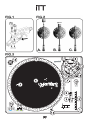
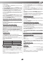
Super High Torque direct drive turntable
PLATTENSPIELER MIT DIREKTANTRIEB UND SUPER HOHEM DREHMOMENT
GIRADISCOS TOTALMENTE MANUAL SUPER HIGH TORQUE
PLATINE MANUELLE À ENTRAÎNEMENT DIRECT (SUPER HIGH TORQUE)
OPERATIONS
MANUAL
BEDIENUNGSHANDBUCH
MANUAL DEL OPERADOR
MANUEL D’INSTRUCTIONS
MULTI LANGUAGE INSTRUCTIONS
ENGLISH.....................................................................................................................................................................................................................PAGE 4
DEUTSCH....................................................................................................................................................................................................................PAGE 6
ESPAÑOL....................................................................................................................................................................................................................PAGE 8
FRANCAIS.................................................................................................................................................................................................................PAGE 10
PLEASE READ BEFORE USING APPLIANCE, IMPORTANT WARNING & SAFETY INSTRUCTIONS!
CAUTION
RISK OF ELECTRICAL SHOCK DO NOT OPEN!
CAUTION: This product satisfies FCC regulations when shielded cables and connectors are used to connect the unit to other equipment. To prevent electromagnetic
interference with electric appliances such as radios and televisions, use shielded
cables and connectors for connections.
regard to proper grounding of the mast and supporting structure, grounding of the
lead-in wire to an antenna discharge unit, size of grounding conductors, location
of antenna-discharge unit, connection to grounding electrodes, and requirements
for the grounding electrode. See Figure B.
The exclamation point within an equilateral triangle is intended to alert the user to
the presence of important operating and maintenance (servicing) instructions in
the literature accompanying the appliance.
LIGHTENING: For added protection for this product during a lightening storm, or
when it is left unattended and unused for long periods of time, unplug it from the
wall outlet and disconnect the antenna or cable system. This will prevent damage
to the product due to lightening and power-line surges.
The lightening flash with arrowhead symbol, within an equilateral triangle, is
intended to alert the user to the presence of uninsulated “dangerous voltage” within the product’s enclosure that may be of sufficient magnitude to constitute a risk
of electric shock to persons.
READ INSTRUCTIONS: All the safety and operating instructions should be read
before the product is operated.
POWER LINES: An outside antenna system should not be located in the vicinity of
overhead power lines or other electric light or power circuits, or where it can fall
into such power lines or circuits. When installing an outside antenna system,
extreme care should be taken to keep from touching such power lines or circuits
as contact with them might be fatal.
RETAIN INSTRUCTIONS: The safety and operating instructions should be retained
for future reference.
OVERLOADING: Do not overload wall outlets, extension cords, or integral convenience receptacles as this can result in a risk of fire or electric shock.
HEED WARNINGS: All warnings on the product and in the operating instructions
should be adhered to.
FOLLOW INSTRUCTIONS: All operating and use instructions should be followed.
OBJECT AND LIQUID ENTRY: Never push objects of any kind into this product
through openings as they may touch dangerous voltage points or short-out parts
that could result in a fire or electric shock. Never spill liquid of any kind on the
product.
CLEANING: The product should be cleaned only with a polishing cloth or a soft dry
cloth. Never clean with furniture wax, benzine, insecticides or other volatile liquids
since they may corrode the cabinet.
SERVICING: Do not attempt to service this product yourself as opening or removing
covers may expose you to dangerous voltage or other hazards. Refer all servicing to qualified service personnel.
ATTACHMENTS: Do not use attachments not recommended by the product manuacturer as they may cause hazards.
DAMAGE REQUIRING SERVICE: Unplug this product from the wall outlet and refer
servicing to qualified service personnel under the following conditions:
WATER AND MOISTURE: Do not use this product near water, for example, near a
bathtub, wash bowl, kitchen sink, or laundry tub; in a wet basement; or near a
swimming pool; and the like.
• When the power-supply cord or plug is damaged.
ACCESSORIES: Do not place this product on an unstable cart, stand, tripod, bracket, or table. The product may fall, causing serious injury to a child or adult, and
serious damage to the product. Use only with a cart, stand, tripod, bracket, or table
recommended by the manufacturer, or sold with the product. Any mounting of the
product should follow the manufacturer’s instructions, and should use a mounting
accessory recommended by the manufacturer.
• If the product has been exposed to rain or water.
CART: A product and cart combination should be moved with care. Quick stops,
excessive force, and uneven surfaces may cause the product and cart combination to overturn. See Figure A.
• If the product has been dropped or damaged in any way.
VENTILATION: Slots and openings in the cabinet are provided for ventilation and to
ensure reliable operation of the product and to protect it from overheating, and
these openings must not be blocked or covered. The openings should never be
blocked by placing the product on a bed, sofa, rug, or other similar surface. This
product should not be placed in a built-in installation such as a bookcase or rack
unless proper ventilation is provided or the manufacturer’s instructions have been
adhered to.
• If liquid has been spilled, or objects have fallen into the product.
• If the product does not operate normally by following the operating instructions.
Adjust only those controls that are covered by the operating instructions as an
improper adjustment of other controls may result in damage and will often require
extensive work by a qualified technician to restore the product to its normal operation.
• When the product exhibits a distinct change in performance, this indicates a
need for service.
REPLACEMENT PARTS: When replacement parts are required, be sure the service
technician has used replacement parts specified by the manufacturer or have the
same characteristics as the original part. Unauthorized substitutions may result in
fire, electric shock, or other hazards.
SAFETY CHECK: Upon completion of any service or repairs to this product, ask the
service technician to perform safety checks to determine that the product is in
proper operating condition.
POWER SOURCES: This product should be operated only from the type of power
source indicated on the marking label. If you are not sure of the type of power supply to your home, consult your product dealer or local power company.
WALL OR CEILING MOUNTING: The product should not be mounted to a wall or
ceiling.
LOCATION: The appliance should be installed in a stable location.
HEAT: The product should be situated away from heat sources such as radiators,
heat registers, stoves, or other products (including amplifiers) that produce heat.
NON-USE PERIODS: The power cord of the appliance should be unplugged from the
outlet when left unused for a long period of time.
GROUNDING OR POLARIZATION:
• If this product is equipped with a polarized alternating current line plug (a plug
having one blade wider than the other), it will fit into the outlet only one way. This
is a safety feature. If you are unable to insert the plug fully into the outlet, try
reversing the plug. If the plug should still fail to fit, contact your electrician to
replace your obsolete outlet. Do not defeat the safety purpose of the polarized
plug.
• If this product is equipped with a three-wire grounding type plug, a plug having
a third (grounding) pin, it will only fit into a grounding type power outlet. This is a
safety feature. If you are unable to insert the plug into the outlet, contact your electrician to replace your obsolete outlet. Do not defeat the safety purpose of the
grounding type plug.
POWER-CORD PROTECTION: Power-supply cords should be routed so that they
are not likely to be walked on or pinched by items placed upon or against them,
paying particular attention to cords at plugs, convenience receptacles, and the
point where they exit from the product.
OUTDOOR ANTENNA GROUNDING: If an outside antenna or cable system is connected to the product, be sure the antenna or cable system is grounded so as to
provide some protection against voltage surges and built-up static charges. Article
810 of the National Electrical Code, ANSI/NFPA 70, provides information with
(2)
iTT
(3)
INTRODUCTION:
ASSEMBLY & SET-UP:
Congratulations on purchasing a Gemini iTT fully manual high
torque turntable. This state of the art turntable includes the latest features. Prior to use, we suggest that you carefully read all
the instructions.
SEE FIG. 3 FOR PART NUMBERS AND LOCATIONS.
FEATURES:
- Fully Manual Direct Drive Turntable
- Super high torque (2.2 kg) direct drive turntable
- +/-10% variable pitch slide control
- Solid aluminum platter with easy glide grooves
- Straight tone arm for superior tracking
- Tone arm height adjustment up to 6 mm with lock
- Fully adjustable counter weight & anti-skating controls
- LED illuminated soft touch start/stop & RPM buttons
- 33/45/78 RPM
- Push button quartz lock w/ LED
- Target light with RCA connector
- Removable head shell
- Felt slip mat included
- Detachable RCA & ground cables
VOLTAGE SELECTION:
Rotate the PLATTER (2) until the VOLTAGE SELECTION
SWITCH (3) (located on the TURNTABLE BASE (1)) is visible
through one of the platter holes. Make sure that the VOLTAGE
SELECTOR SWITCH (3) is set to the correct voltage.
WARNING: IF YOU TRY TO OPERATE THE TURNTABLE WITH THE INCORRECT VOLTAGE SETTING, IT CAN DAMAGE YOUR TURNTABLE.
TURNTABLE INSTALLATION:
1. Put the SLIPMAT (4) on the PLATTER (2).
2. Set the TURNTABLE BASE (1) on a flat, level surface free of
vibration. Use the turntable feet to stabilize the unit horizontally.
3. Try to place the unit as far away from the speakers as possible.
4. Keep the unit away from direct exposure to the sun, heat,
moisture or dirt.
5. Keep the unit well ventilated.
CARTRIDGE INSTALLATION: (SEE FIG. 1)
PRECAUTIONS:
1. Read all operating instructions before using this equipment.
2. The apparatus should not be exposed to dripping or splashing, and no objects filled with liquids such as vases should be
placed on the apparatus.
3. To reduce the risk of electrical shock, DO NOT OPEN THE
UNIT. Please contact the Gemini Service Department or your
authorized dealer to speak to a qualified service technician.
Because all cartridges have their own designs, please refer to
your particular cartridge's instructions to insure proper installation. If you are using a pre-mounted or integrated cartridge, you
can jump ahead to HEADSHELL INSTALLATION.
1. Connect the lead wires to the cartridge terminals. For your
convenience, the terminals of most cartridges are color-coded.
Connect each lead wire to the terminal of the same color. In
case your cartridge is not marked the positive leads are the ones
on top negative below, left are left, and right is right.
IN THE USA ~ IF YOU EXPERIENCE PROBLEMS WITH THIS UNIT
CALL GEMINI CUSTOMER SERVICE AT: 1 (732) 738-9003. DO NOT
ATTEMPT TO RETURN THIS EQUIPMENT TO YOUR DEALER.
White (L+)................................................Left Channel +
4. Tone Arm bearings are factory set and sealed. Any attempt at
adjustment will void the warranty.
Red (R+)...............................................Right Channel +
Blue (L-)...................................................Left Channel -
5. Be sure that all AC power is OFF while making connections.
6. Cables should be low capacitance, shielded and of proper
length. Make sure that all plugs and jacks are tight and properly
connected.
7. Always, begin with the audio level faders/volume controls set
at minimum and the speaker volume control(s) set to OFF. Wait
8 to 10 seconds prior to turning up the speaker volume to prevent the transient "POP" that could result in speaker/crossover
damage.
8. DO NOT EXPOSE THIS UNIT TO RAIN OR MOISTURE.
9. DO NOT USE ANY SPRAY CLEANER OR LUBRICANT ON
ANY CONTROLS OR SWITCHES.
PARTS CHECKLIST:
Green (R-).............................................Right Channel 2. Mount the cartridge in the HEADSHELL (5) and tighten it with
the screws included with the cartridge.
HEADSHELL INSTALLATION:
Insert the HEADSHELL (5) into the front of the tubular TONE
ARM (7). While holding the HEADSHELL (5) firmly in a horizontal position, turn the LOCKING NUT (6) counter clockwise until
the HEADSHELL (5) is locked in place.
COUNTERWEIGHT INSTALLATION: (SEE FIG. 2)
1. Slide the COUNTERWEIGHT (8) onto the rear of the TONE
ARM (7) with the numbered stylus gauge facing forward.
2. Twist the COUNTERWEIGHT (8) counter clockwise lightly, to
screw it onto the rear of the TONE ARM (7).
Please make sure the following parts are included with your
iTT:
ADJUSTING HORIZONTAL ZERO (0)
BALANCE AND STYLUS PRESSURE:
Turntable unit..........................................................................1
1. Without touching the stylus tip, remove the stylus protector (if
your cartridge has a detachable one).
Turntable platter......................................................................1
Slipmat....................................................................................1
Counterweight........................................................................ 1
Headshell with cartridge.........................................................1
RCA target light……………………………….............…………1
(4
4)
2. Release the ARM CLAMP (10) and lift the TONE ARM (7) off
the ARM REST (11).
3. Counter clockwise advancement of the COUNTERWEIGHT
(8) will cause the cartridge side of the TONE ARM (7) to be lowered; turning it clockwise will cause the opposite. Turn the
COUNTERWEIGHT (8) clockwise or counter clockwise as needed until the TONE ARM (7) is balanced horizontally. You can
ITT
easily tell this by watching for the point where the TONE ARM
(7) "floats" freely.
4. Place TONE ARM (7) on ARM REST (11) and lock it in place
with the ARM CLAMP (10).
5. With the TONE ARM (7) locked on the ARM REST (11), hold
the COUNTERWEIGHT (8) steady with one hand while rotating
the STYLUS PRESSURE RING (9) until the numeral "0" on the
ring aligns with the center line on the TONE ARM (7) rear shaft.
The HORIZONTAL ZERO (0) balance should be completed.
6. Re-float the TONE ARM (7) to ensure horizontal zero (0) balance. If zero balance has not been maintained, repeat counterweight steps 3 - 5.
7. After adjusting the HORIZONTAL ZERO (0) balance, turn the
balanced COUNTERWEIGHT (8) counter clockwise until the
cartridge manufacturer's recommend stylus pressure appears
on the STYLUS PRESSURE RING (9) where it meets the center line of the TONE ARM (7) rear shaft.
4. Remove the stylus protector (if applicable to your cartridge).
5. Release the ARM CLAMP (10) found on the ARM REST (11).
6. Push the START/STOP (15) button. The turntable PLATTER
(2) will start to spin.
7. Carefully position the TONE ARM (7) over the desired position over the record. Lower the TONE ARM (7) slowly, while letting go of the TONE ARM (7) over the record where you want to
play.
8. When play is over, raise the TONE ARM (7), move it onto the
ARM REST (11), and secure it with the ARM CLAMP (10).
9. You now have the option of turning off the power by turning
the POWER (13) switch to the "OFF" position, or stopping the
PLATTER (2) by pushing the START/STOP (15) button.
INTERRUPTING PLAY:
ADJUSTING THE ANTI-SKATING CONTROL:
1. Pushing the START/STOP (15) button will cause the record to
stop exactly when the START/STOP (15) button is pressed
while playing.
Set the ANTI-SKATING CONTROL (12) to the same value as
the stylus pressure.
2. Press the START/STOP (15) button again to start playback
with a short delay effect.
NOTE: IF YOUR TURNTABLE CAME WITH A CN-1000 CARTRIDGE, IT HAS A
RECOMMENDED TRACKING FORCE OF 3.0 GRAMS AND CAN HAVE RANGE
FROM 2.5-3.5 GRAMS.
ADJUSTING THE PITCH CONTROL:
ADJUSTING TONE ARM HEIGHT:
The iTT comes with an adjustable TONE ARM BASE (7). This
feature is generally used when a larger or smaller sized headshell is used for record playing. You may adjust the height of the
TONE ARM (7) by unlocking the base with the use of the LOCK
SWITCH (20) located next to the ANTI SKATE CONTROL (12).
Then adjust the TONE ARM ADJUSTMENT LEVER (8), located below the counter weight, to adjust the height of the TONE
ARM (7) by 6 mm.
CONNECTIONS:
2. See TABLE A for proper connection of the output RCA plugs
and ground connector. Make sure that all the plugs are firmly
plugged into the appropriate jacks (phono inputs).
NOTE: TO REDUCE HUM, MAKE SURE THE GROUND LUG IS FIRMLY CONNECTED TO THE GROUND SCREW.
TABLE A:
PHONO L CHANNEL
R (RED)
PHONO R CHANNEL
GND (SPADE LUG)
GND SCREW
3. To lock the PITCH SLIDE CONTROL (17) press the QUARTZ
LOCK BUTTON (18) located above the PITCH SLIDE CONTROL (17).
TURNTABLE SECTION:
Type..............................................Direct Drive Manual Turntable
Drive Method............................High Torque (2.2 kg) Direct Drive
Motor.............................................................................DC Motor
Speed............................................................33 1/3, 45, 78 RPM
Wow and Flutter...................................Less than 0.15% WRMS*
*THIS RATING REFERS TO THE TURNTABLE ASSEMBLY AND PLATTER
ONLY AND EXCLUDES EFFECTS OF RECORDS, CARTRIDGES OR TONEARMS.
MIXER OR RECIEVER
L (WHITE)
2. When the PITCH SLIDE CONTROL (17) is positioned off center, the pitch can vary ±10% depending on the position of the
PITCH SLIDE CONTROL (17).
SPECIFICATIONS:
1. Plug the AC power plug into an appropriate outlet.
OUTPUT CONNECTORS
1. The iTT is equipped with a PITCH SLIDE CONTROL (17).
When the PITCH SLIDE CONTROL (17) is in the center position, the speed will be 33, 45, or 78 depending on which SPEED
SELECTOR (16) button is pushed.
TONEARM SECTION:
Type...................................Statically Balanced Straight Tonearm
Headshell Weight....................................................5.6 g
OPERATING INSTRUCTIONS:
GENERAL:
BASIC OPERATION:
1. Turn the POWER (13) switch to the "ON" position, at which
point the TARGET LIGHT (14) will light up, TARGET LIGHTS
(14) are an optional accessory available at your local retailer.
2. Place a record on the SLIPMAT (4) which sits on the PLATTER (2).
3. Select the desired speed by depressing the 33, 45 or 78 (33
& 45 simultaneously) SPEED SELECTOR (16) button.
(5)
Power Supply...............................AC 115 V~60 Hz/230 V~50 Hz
Power Consumption.............................................................30 W
Dimensions...................................................17.75" x 5.75" x 14"
...................................................................(450 x 136 x 352 mm)
Weight................................................................20.1 lbs. (9.1 kg)
SPECIFICATIONS ARE SUBJECT TO CHANGE WITHOUT NOTICE. THE
WEIGHT AND DIMENSIONS SHOWN ARE APPROXIMATE.
EINFÜHRUNG:
AUFBAUANLEITUNG:
Vielen Dank das Sie sich für den manuellen Gemini iTT
Plattenspieler mit Direktantrieb und super hohem Drehmoment
entschieden haben. Der iTT wurde nach dem neuesten Stand
der Technik hergestellt und ist mit den modernsten Features
ausgestattet. Bitte lesen und beachten Sie vor der
Inbetriebnahme alle folgenden Anweisungen.
SIEHE FIG.3 FÜR TEILENUMMERN UND PLATZIERUNG
AUSSTATTUNG:
Drehen Sie den PLATTENTELLER (2) bis der Schalter VOLTAGE SELECTION SWITCH (3) (auf der TURNTABLE BASE
(1)) durch eines der Löcher im Teller sichtbar ist und überzeugen Sie sich, das die Schalterstellung mit der Netzspannung
übereinstimmt.
WARNUNG: IST DIE FALSCHE SPANNUNG EINDESTELLT; KANN DER PLATTENSPIELER BEIM EINSCHALTEN ZERSTÖRT WERDEN.
- Manueller direktangetriebener Plattenspieler
- Motor mit super starkem Drehmoment (2,2Kg)
- Stufenloser Pitchfader +/-10%
- Aluminium-Druckguß-Plattenteller mit Fingergleitmulden
- Gerader Tonarm für bestes Abtastverhalten
- Tonarmhöhenverstellung bis 6mm mit Arretierung
- Antiskating und Tonarmgegengewicht einstellbar
- Softtouch Start/Stop & RPM Taster mit LED
- 33/45/78 RPM
- Quartz lock Taster mit LED
- Nadelbeleuchtung mit Cinchanschluß
- Austauschbarer Tonkopf mit ½" Systembefestigung
- Filz Slipmat inklusive
- Abnehmbares Cinchkabel mit Masseleitung
AUFBAU DES PLATTENSPIELERS:
1. Legen Sie den PLATTENTELLER (2) auf die Motorspindel
auf der BASE (1). Halten Sie die Mitte der Achse fest und
drehen Sie langsam den TELLER (2), bis die beiden Pins einrasten.
2. Legen Sie die SLIPMAT (4) auf den TELLER (2).
3. Stellen Sie den Plattenspieler auf einen ebenen festen Platz
(Regal, Tisch usw.).
4. Suchen Sie eine Aufstellungmöglichkeit weit von den
Lautsprechern entfernt.
VORSICHTSMAßNAHMEN:
1. Lesen Sie bitte alle Bedienungsanweisungen vor der
Inbetriebnahme.
2. Schützen Sie den Plattenspieler vor hoher Feuchtigkeit und
Spritzwasser. Stellen Sie keine Vasen oder ähnliche wassergefüllte Gegenstände auf das Gerät.
3. Um einen Stromschlag zu vermeiden, öffnen Sie das Gerät
nicht! BITTE KONTAKTIEREN SIE IHREN HÄNDLER ODER
EINEN QUALIFIZIERTEN SERVICETECHNIKER.
4. Die Tonarmlager sind werksseitig justiert und versiegelt. Nicht
nachjustieren, da sonst die Garantie erlischt.
5. Stellen Sie sicher, das der Netzschalter ausgeschaltet ist
bevor Sie den Plattenspieler anschließen.
6. Verwenden Sie nur hochwertige abgeschirmte Kabel in
entsprechender Länge. Achten Sie auf festen und richtigen Sitz
der Stecker und Buchsen.
7. Beginnen Sie immer mit der Fader-/Reglerstellung "Minimum"
und schalten Sie Ihren Endverstärker oder die Aktivlautsprecher
zuletzt ein(ca. 10sek. nach dem Mixer) um ein Einschaltknacken
zu vermeiden.
8. SETZEN SIE DIESES GERÄT NIE REGEN ODER
FEUCHTIGKEIT AUS.
9. BENUTZEN SIE KEIN KONTAKTSPRAY
ÄHNLICHES FÜR FADER ODER SCHALTER.
NETZSPANNUNG EINSTELLEN:
ODER
5. Setzen Sie den Plattenspieler keiner direkten
Sonneneinstrahlung aus und wählen Sie einen sauberen, trockenen Aufstellungsort.
6. Achten Sie auf gute Luftzirkulation.
TONABNEHMEREINBAU: (SIEHE FIG. 1)
Da alle Tonabnehmer verschieden sind, lesen Sie bitte die
Montageanweisungen Ihres Systems. Wenn Sie ein vormontiertes System oder einen Tonabnehmer wie z.B. ORTOFON
(Banane) verwenden, Lesen Sie bitte weiter ab
"Tonkopfmontage".
ANSCHLIEßEN DES SYSTEMS:
1. Die meisten Tonabnehmer sind mit einer Farbcodierung
versehen um das Anschließen zu erleichtern.Stecken Sie das
jeweils passende Kabel auf einen Systemkontakt. Falls Ihr
System keine Markierung haben sollte, sind die oberen
Anschlüsse + und die Unteren -, sowie die linken beiden linker
Kanal und die rechten beiden rechter Kanal.Connect the lead
wires to the cartridge terminals.
Weiß (L+)...........................................................linker Kanal +
Blau (L-)..............................................................linker Kanal Rot (R+)...........................................................rechter Kanal +
Green (R-)........................................................rechter Kanal 2. Befestigen Sie den Tonabnehmer mit den, dem System
beiliegenden Schrauben, am TONKOPF (HEADSHELL) (5).
TONKOPFMONTAGE:
TEILELISTE:
Bitte prüfen sie die Vollständigkeit des Plattenspielers iTT:
Plattenspieler...........................................................................1
Plattenteller..............................................................................1
Slipmat.....................................................................................1
Tonarmgegengewicht..............................................................1
Tonkopf....................................................................................1
Nadelbeleuchtung….........…………………………...................1
(6)
Schieben Sie den TONKOPF (HEADSHELL) (5) in die
Aufnahmehülse am vorderen Ende des TONARMS (7). Halten
Sie den TONKOPF (5) fest in horizontaler Position und drehen
Sie die VERRIEGELUNGSMUTTER (6) entgegen dem
Uhrzeigersinn bis Sie einrastet. Wenden Sie beim Drehen keine
starke Kraft auf, um ein Überdrehen zu vermeiden.
MONTAGE DES TONARMGEGENGEWICHTS:
(SIEHE FIG. 2)
1. Schieben Sie das GEWICHT (COUNTERWEIGHT) (8) auf
das hintere Ende des TONARMS (7), so das die Skalenseite
nach vorn zeigt.
2. Drehen Sie das GEWICHT (8) leicht entgegen dem
Uhrzeigersinn, um es weiter auf das Ende des Tonarms zu
schrauben.
ITT
EINSTELLUNG DER NULLBALANCE UND
DER AUFLAGEKRAFT:
1. Entfernen Sie den Nadelschutz (falls vorhanden), ohne die
Nadel zu berühren.
2. Entriegeln Sie den TONARM (7), indem Sie den Bügel (ARM
CLAMP) (10) des TONARM-HALTERS (11) öffnen und heben
Sie den Arm aus dem TONARMHALTER (ARM REST) (11).
3. Bringen Sie den TONARM (7) durch Drehen des
GEWICHTES (8) in eine waagerechte, horizontale
Schwebestellung.
4. Legen Sie nun den TONARM (7) wieder auf den
TONARMHALTER (11) und befestigen Sie den Arm mit dem
BÜGEL (10).
5. Ist der TONARM (7) wieder im HALTER (11) befestigt, halten
Sie mit einer Hand das GEWICHT (8) fest und drehen mit der
anderen Hand den SKALENRING (9) auf "0", nach der
Mittelllinie am hinteren Tonarmende. Damit ist der Nullpunkt
eingestellt.
6. Lösen Sie den TONARM (7) nochmals und überprüfen Sie,
ob der Arm sich noch waagerecht in der Schwebe befindet. Ist
dies nicht der Fall wiederholen Sie die Punkte 2-5.
7. Ist die Nullpunkteinstellung beendet, drehen Sie das
GEWICHT (8) entgegen dem Uhrzeigersinn, bis die gewünschte
Zahl des SKALENRINGS (9) (Auflagekraft nach Angabe des
Systemherstellers) mit der Mittelllinie des TONARMES (7)
übereinstimmt.
EINSTELLUNG DER ANTISKATINGKRAFT:
Drehen Sie den Regler ANTI-SKATING CONTROL (12) auf
die gleiche Zahl wie die Auflagekraft.
JUSTAGE DER TONARMHÖHE:
Der iTT ist mit einer Tonarmhöhenverstellung ausgestattet.
Diese dient dazu, unterschiedliche Systeme anpassen zu können und den TONARM (7) in der Waage zu halten. Zum
Einstellen der Tonarmhöhe lösen sie die Verriegelung LOCK
SWITCH (20) neben dem ANTISKATINGREGLER (12). Jetzt
können Sie mt dem Drehkranz TONE ARM ADJUSTMENT
LEVER (21) an der Tonarmbasis die Tonarmhöhe um bis zu
6mm verändern.
ANSCHLÜSSE:
3. Wählen Sie mit den Tastern 33, 45 or 78 (33+45 gleichzeitig)
SPEED SELECTOR (16) die gewünschte Geschwindigkeit aus.
4. Entfernen Sie den Nadelschutz (falls vorhanden) vom
System.
5. Lösen Sie den BÜGEL (10) des TONARMHALTERS (11).
6. Drücken Sie die Taste START/STOP (15) und der
Plattenteller beginnt sich zu drehen.
7. Positioniere Sie den TONARM (7) nun vorsichtig über der
Stelle die Sie abspielen wollen. Senken Sie den TONARM (7)
jetzt per Hand oder mit dem TONARMLIFT (19) vorsichtig ab
und lassen Sie die Musik in der gewünschten Lautstärkr abspielen.
8. Ist das Stück zu Ende, legen Sie den TONARM (7) wieder auf
dem TONARMHALTER (11) ab und sichern den Arm mit dem
BÜGEL (10).
9. Jetzt können Sie entweder den Schalter POWER (13) auf
"OFF" drehen oder den Plattenteller durch nochmaliges
Drücken der Taste START/STOP (15) anhalten.
SPIELUNTERBRECHUNG:
1. Drücken Sie die Taste START/STOP (15) während des
Abspielens, so stoppt der Motor sofort und bleibt an der Stelle
stehen.
2. Wird die Taste START/STOP (15) nochmals betätigt, läuft der
Motor mit einer kurzen Verzögerung wieder an (Hochlaufzeit).
EINSTELLUNG DER TONHÖHE (PITCH CONTROL):
1. Der iTT ist mit einem PITCHFADER (PITCH SLIDE CONTROL) (17) ausgestattet. Ist der PITCHFADER (17) in der
Mittelstellung entspricht die Geschwindigkeit der Einstellung der
Tasten SPEED SELECTOR (16).
2. Bewegen Sie den PITCHFADER (17) aus der Mittenstellung
heraus, so können Sie die Geschwindigkeit und damit auch die
Tonhöhe um +/- 10% verändern.
3. Wenn Sie die Taste QUARTZ LOCK (18) betätigen, ist der
Pitchfader abgeschaltet und der Teller dreht sich wieder exakt
mit der gewählten Geschwindigkeit.
TECHNISCHE DATEN:
1. Stecken Sie den Netzstecker in eine Schukosteckdose.
2. Zum Anschließen der Cinchleitung und des Erddrahtes
beachten Sie bitte TABLE A Achten Sie auf festen und richtigen
Sitz der Stecker (Phonoeingänge).
ANMERKUNG: UM BRUMMPROBLEME ZU VERMEIDEN; MUß DIE ERDVERBINDUNG RICHTIG ANGESCHLOSSEN SEIN! SIEHE ANSCHLUSSBILD.
TABLE A:
AUSGANGSANSCHLUSS
2. Legen Sie eine Schallplatte auf die SLIPMAT (4) auf dem
PLATTENTELLER (2).
PHONO L KANAL
R (ROT)
PHONO R KANAL
ERDUNG (FLACHOSE)
ERDUNNGSSCHRAUBE
Typ..............................manueller Plattenspieler mit Direktantrieb
Antriebsart.....Direktantrieb mit super hohem Drehmoment (2.2 kg)
Motor................................................................Gleichstrommotor
Geschwindigkeit............................................33 1/3, 45, 78 RPM
Wow und Flutter...................................kleiner als 0.15% WRMS*
*DIESE ANGABE BEZIEHT SICH NUR AUF DEN PLATTENSPIELER MIT PLATTENTELLER; SCHALLPLATTEN; TONARM UND SYSTEM SIND NICHT MIT
EINBEZOGEN.
MIXER ODER RECIEVER
L (WEIB)
PLATTENSPIELER:
TONARM:
Typ....................................Statisch balancierter, gerader Tonarm
Tonkopfgewicht....................................................................5.6 g
ALLGEMEIN:
BEDIENUNGSANWEISUNG:
GRUNDFUNKTIONEN:
1. Stecken Sie die Nadelbeleuchtung TARGET LIGHT (14) in
die CINCHBUCHSE (14) am Rand des TELLERS (2). Drehen
Sie den Schalter POWER (13) auf "ON" und die
NADELBELEUCHTUNG (14) leuchtet auf.
(7
7)
Spannungsversorgung.................AC 115 V~60 Hz/230 V~50 Hz
Stromaufnahme...................................................................30 W
Maße..........................................................(450 x 136 x 352 mm)
Gewicht............................................................................(9.1 kg)
TECHNISCHE ÄNDERUNGEN VORBEHALTEN.
INTRODUCCIÓN:
MONTAJE Y CONFIGURACIÓN:
Felicitaciones por su compra de un giradiscos Gemini iTT
totalmente manual super high torque. Este giradiscos de la
más avanzada tecnología está dotado de características ultramodernas. Antes de usarlo, le recomendamos leer cuidadosamente todas las instrucciones.
VÉASE LA FIG. 3 PARA NÚMEROS DE PIEZA Y UBICACIONES.
CARACTERÍSTICAS:
- Giradiscos totalmente manual
- Motor super high torque (2.2 kg)
- Control deslizante de pitch +/-10%
- Plato sólido de aluminio con agujeros de deslizamiento
- Brazo recto para un superior agarre en el disco
- Ajuste de la altura del brazo hasta 6 mm con bloqueo
- Controles totalmente ajustables de peso y anti-skating
- Botones de acción suave e iluminados por LED para start/stop
- 33/45/78 RPM
- Botón de quartz lock con LED
- Conector RCA para luz de posición
- Porta cápsulas removible
- Patinador de felpa incluido
- Cables de señal RCA y masa removibles
PRECAUCIONES:
1. Deberán leerse todas las instrucciones de operación antes de
usar el equipo.
2. Este aparato no debería estar expuesto al goteo o a las
salpicaduras y ningún objeto lleno de líquido, tal como floreros,
debería estar colocado sobre el aparato.
3. Para reducir el riesgo de descarga eléctrica, no abra la
unidad. NO CONTIENE PIEZAS REEMPLAZABLES POR EL
USUARIO. Sírvase comunicarse con el Departamento de
Servicio Gemini o su distribuidor autorizado y hablar con un técnico de servicio calificado.
SELECCION DEL VOLTAJE:
Haga girar el PLATO - PLATTER (2) hasta que se vea el
SELECTOR DE VOLTAJE - VOLTAGE SELECTOR (3) (colocado en la BASE DEL TOCADISCO - TURNTABLE BASE (1)) a
través de uno de los orificios en el plato. Cerciórese de que el
SELECTOR DE VOLTAJE (3) esté arreglado para el voltaje correcto.
ADVERTENCIA: SI TRATA DE HACER FUNCIONAR EL GIRADISCOS CON EL
VOLTAJE INCORRECTO, CORRE EL RIESGO DE DAÑARLO.
INSTALACION DEL TOCADISCO:
1. Coloque el PLATO (2) en la BASE DEL GIRADISCOS (1).
Centre y sujete el eje mientras gira el PLATO (2) hasta que los
fijadores del PLATO (2) encajen en el motor.
2. Coloque la PATINADOR - SLIPMAT (4) sobre el PLATO (2).
3. Ponga la BASE DEL TOCADISCO - TURNTABLE BASE (1)
sobre una superficie plana y nivelada sin vibraciones. Use las
patas del giradiscos para estabilizar la unidad en sentido horizontal.
4. Trate de colocar la unidad lo más lejos posible de los altavoces.
5. Mantenga la unidad alejada de la exposición directa del sol,
calor, humedad o suciedad.
6. Mantenga la unidad bien ventilada.
INSTALACIÓN DE LA CÁPSULA:
(VEA FIG. 1)
Al tener cada cápsula su propio diseño, por favor refierase a
las instrucciones propias de cada una para asegurar una correcta instalación. Si esta usando una cápsula pre-montada o de
cuerpo unico, usted puede saltar hasta CABEZAL HEADSHELL.
4. Los cojinetes del brazo de fonocaptor están ajustados y sellados en fábrica. Cualquier intento de ajuste dejará sin efecto la
garantía.
INSTALACIÓN DE LA CÁPSULA:
5. Cerciórese de que toda la corriente CA esté APAGADA para
efectuar las conexiones.
Debido a que todos las cápsulas son de diseño distinto, sírvase referirse a las instrucciones de su cápsula específica, para
garantizar la instalación correcta.
6. Los cables deberán ser de baja capacidad, blindados, y de
apropiado longitud. Cerciórese de que todos los enchufes y
jacks estén apretados y debidamente conectados.
7. Comience siempre con los atenuadores de nivel de
audio/control de volumen fijados en el nivel mínimo y el control
de volumen de los altavoces fijados en APAGADO. Espere 8 a
10 segundos antes de aumentar el volumen de los altoparlantes
para evitar el "chasquido" transitorio que podría ocasionar
daños a los altavoces.
8. NO DEJE ESTA UNIDAD EXPUESTA A LLUVIA O
HUMEDAD.
9. NO USE NINGÚN LIMPIADOR DE SPRAY O LUBRICANTE
EN CUALQUIERA DE LOS CONTROLES O INTERRUPTORES.
LISTA DE COMPROBACIÓN DE PIEZAS:
(VÉASE LA FIG. 1)
1. Conecte los alambres conductores a los terminales de la cápsula. Para su conveniencia, los terminales de la mayoría de las
cápsulas están codificados por colores. Conecte cada alambre
conductor al terminal del mismo color.
Blanco (I+).................................................................Canal izquierdo +
Azul (I-).......................................................................Canal izquierdo Rojo (D+).....................................................................Canal derecho +
Verde (D-)....................................................................Canal derecho -
2. Monte la cápsula dentro del PORTACAPSULAS - HEADSHELL (5) y apriételo con los tornillos incluidos con la cápsula
Inserte el PORTACAPSULAS - HEADSHELL (5) en la parte
delantera del BRAZO DE FONOCAPTOR (7) tubular.
Sosteniendo el PORTACAPSULAS (5) firmemente en posición
horizontal, gire la TUERCA FIADORA - LOCKING NUT (6)
hacia la izquierda hasta que el PORTACAPSULAS (5) se haya
asegurado en posición.
INSTALACIÓN DEL CONTRAPESO: (VÉASE LA FIG. 2)
Por favor asegurese que estas piezas estan incluidas en el
embalaje del iTT:
Unidad de giradiscos.............................................................1
Plato del giradiscos................................................................1
Patinador................................................................................1
Contrapeso............................................................................1
Porta cápsulas.......................................................................1
Luz de posición RCA……………………………..…………..........1
(8)
1. Deslice el CONTRAPESO - COUNTERWEIGHT (8) sobre la
parte posterior del BRAZO DEL FONOCAPTOR - TONE ARM
(7) con la medida de la aguja numerada hacia el frente.
2. Gire el CONTRAPESO - COUNTERWEIGHT (8) ligeramente
hacia la izquierda para enroscarlo en la parte posterior del
BRAZO DE FONOCAPTOR - TONE ARM (7).
ITT
AJUSTE DEL EQUILIBRIO CERO (0) HORIZONTAL Y PRESIÓN DE LA AGUJA:
INSTRUCCIONES DE OPERACIÓN:
OPERACIÓN BÁSICA:
1. Sin tocar la punta de la aguja, quite el protector de aguja (si
el de su cápsula es removible).
2. Suelte el SUJETABRAZO - ARM CLAMP (10) y levante el
BRAZO DE FONOCAPTOR - TONE ARM (7) del DESCANSILLO - ARM REST (11).
3. Si el COUNTERWEIGHT (8) se avanza hacia la izquierda, se
bajará el lado del cartucho del TONE ARM (7). Si el CONTRAPESO (8) se avanza hacia la derecha ocurrirá lo contrario.
Gire el CONTRAPESO (8) hacia la derecha o la izquierda según
sea necesario hasta que el BRAZO DE FONOCAPTOR (7) esté
horizontalmente equilibrado. Ese equilibrio es fácil de determinar; espere el punto en que el TONE ARM (7) "flote" libremente.
4. Coloque el TONE ARM (7) sobre el ARM REST (11) y
asegúrelo en posición con el SUJETABRAZO - ARM CLAMP
(10).
5. Con el BRAZO FONOCAPTOR (7) enganchado en el ARM
REST (11), sostenga el COUNTERWEIGHT (8) en una mano y
gire el ANILLO DE STYLUS PRESSURE RING (9) hasta que el
número "0" en el anillo se alinee con la línea central del eje
trasero del BRAZO FONOCAPTOR (7). El EQUILIBRIO HORIZONTAL EN CERO (0) deberá quedar completo.
6. Flote de nuevo el BRAZO FONOCAPTOR (7) para asegurarse que se haya obtenido el EQUILIBRO HORIZONTAL EN
CERO (0). Si no se ha mantenido este equilibrio, repita los
pasos de contrapeso 3 al 5.
7. Después de ajustar el EQUILIBRIO CERO (0) HORIZONTAL, gire COUNTERWEIGHT (8) equilibrado hacia la izquierda
hasta que aparezca en el STYLUS PRESSURE RING (9) la presión de aguja recomendada del fabricante del cartucho en el
punto donde coincide con la línea central del eje posterior del
TONE ARM (7).
AJUSTE DEL CONTROL ANTIDESLIZANTE:
Fije el ANTI-SKATING CONTROL (12) al mismo valor que la
presión de la aguja.
AJUSTE DE LA ALTURA DEL BRAZO:
El iTT lleva un BRAZO (7) con base ajustable en altura. Esta
función se utilice cuando se usan cápsulas muy grandes o
demasiado pequeñas en la reproducción. Usted debe ajustar la
altura del BRAZO (7) desenclavando la fijación de la base usando el LOCK SWITCH (20) que se encuentra cerca del ANTI
SKATE CONTROL (12).Luego ajuste el AJUSTE DE BRAZO
(21), que se encuentra debajo del CONTRAPESO (8), para
nivelar la altura del BRAZO (7) hasta 6 mm, de acuerdo con las
especificaciones del fabricante de su cápsula.
CONEXIONES:
1. Conecte el enchufe CA en una base apropiada.
2. Véase el CUADRO A para las conexiones apropiadas de
los enchufes de salida RCA y el conector a tierra. Cerciórese
de que todos los enchufes estén firmemente conectados en
los jack apropiados (entradas phono). Para reducir el zumbido,
cerciórese de que la orejeta a tierra esté firmemente conectado al tornillo de tierra.
CUADRO A
1. Conecte la LUZ DE POSICIÓN (14) en el RCA (14).
Encienda la ALIMENTACION (13) en la posición "ON" y en ese
momento la LUZ (14) se iluminará.
2. Ponga un disco sobre la PATINADOR - SLIPMAT (4) que
descansa sobre el PLATO - PLATTER (2).
3. Seleccione la velocidad deseada pulsando 33, 45 o 78 (33 y
45 simultáneamente) en el SELECTOR DE VELOCIDAD (16).
4. Quite el protector de aguja (si se aplica a su cápsula).
5. Suelte el SUJETABRAZO - ARM CLAMP (10) que se
encuentra en el DESCANSILLO - ARM REST (11).
6. Oprima el BOTÓN DE ARRANQUE/PARADA START/STOP (15). El PLATO - PLATTER (2) del giradiscos
empezará a girar.
7. Sitúe el brazo de fonocaptor arriba del surco deseado en el
disco y ponga la PALANCA DE INDICACION en la posición de
"ABAJO". El BRAZO DE FONOCAPTOR - TONE ARM (7) se
bajará lentamente sobre el disco en cuyo momento empezará a
reproducir.
8. Una vez que haya terminado de reproducir, levante el
BRAZO DE FONOCAPTOR - TONE ARM (7), MUEVALO hacia
el DESCANSILLO - ARM REST (11) y fíjelo con el
SUJETABRAZO - ARM CLAMP (10).
9. Ahora tiene la opción de apagar la unidad, pasando el INTERRUPTOR DE ALIMENTACIÓN - POWER (13) a la posición de
"APAGADO" o de detener el PLATO - PLATTER (2), oprimiendo el BOTÓN DE ARRANQUE/PARADA - START/STOP (15).
INTERRUPCIÓN DE LA REPRODUCCIÓN:
1. Pulsando el START/STOP (15) se parará la reproducción
justo en ese instante.
2. Pulsando el START/STOP (15) de nuevo se reanudará la
reproducción en el lugar anteriormente detenido.
AJUSTANDO EL PITCH CONTROL:
1. El iTT está equipado con CONTROL DESLIZANTE DE
PITCH (17). Cuando el PITCH CONTROL (17) está en la posición central, la velocidad será 33, 45, o 78 dependiendo de en
que posición este el SELECTOR DE VELOCIDAD (16).
2. Cuando el CONTROL PITCH (17) está posicionado fuera del
centro, el pitch puede variar ±10% dependiendo de la posición
del CONTROL PITCH (17).
3. Para fijar el CONTROL PITCH (17) a cero, pulse el QUARTZ
LOCK (18) alojado por encima del CONTROL PITCH (17).
ESPECIFICACIONES:
SECCIÓN GIRADISCOS:
Tipo......................................Giradiscos Manual Tracción directa
Metodo de tracción....Tracción Directa Super High Torque (2.2 kg)
Motor.............................................................................DC Motor
Velocidad.....................................................33 1/3, 45, 78 RPM
Ruido y Fluctuación............................Menor de 0.15% WRMS*
*ESTE DATO SE REFIERE AL GIRADISCOS MONTADO SOLO CON EL PLATO
Y EXCLUYE RUIDOS PRODUCIDOS POR DISCOS, CÁPSULAS O BRAZOS.
SECCIÓN BRAZO:
Tipo..............................Brazo recto Estáticamente Balanceado
Peso del portacápsulas......................................................5.6 g
GENERAL:
CONECTORES DE SALIDA
Alimentación................................AC 115 V~60 Hz/230 V ~50 Hz
Consumo.............................................................................30 W
Dimensiones.................................................17.75" x 5.75" x 14"
...................................................................(450 x 136 x 352 mm)
Peso..................................................................20.1 lbs. (9.1 kg)
MEZCLADOR OR RECEPTOR
I (BLANCO)
I CANAL DEL FONOGRAFO
D (ROJO)
D CANAL DEL FONOGRAFO
TIERRA (OREJETA DE PALETA)
TORNILLO DE TIERRA
(9)
ESPECIFICACIONES SUJETAS A VARIACIÓN SIN PREVIO AVISO.
INTRODUCTION:
MONTAGE & INSTALLATION:
Félicitations concernant l'achat de la platine vinyle Gemini iTT.
Cette platine manuelle à entraînement direct (Super High
Torque) est dotée des dernières évolutions technologiques, est
couverte par une garantie de 3 années. Nous vous recommandons de lire soigneusement l'ensemble des instructions qui suivent.
VOIR FIG. 3 POUR LA NUMEROTATION ET L'INSTALLATION DES DIFFERENTES PIECES.
CARACTERISTIQUES:
- Platine vinyle manuelle à entraînement direct
- Moteur Hi-Torque (Couple: 2.2 Kg)
- Vitesse réglable par pitch linéaire +/-10%
- Plateau de lecture en aluminium
- Bras de lecture droit
- Réglage de la hauteur du bras lecture jusqu'à 6mm + verrouillage
- Contre-poids & anti-skating réglables
- Touches démarrage/stop & vitesse de lecture rétro-éclairées
- Vitesse de lecture: 33/45/78 TRS/MN
- Fonction Quartz Lock (Mise en/hors service du réglage de
vitesse par pitch)
- Eclairage de la tête de lecture amovible sur embase RCA
- Porte-cellule amovible
- Livrée avec feutrine
- Livrée avec cordon RCA + terre
SELECTION DE LA TENSION D'ALIMENTATION:
Faîtes tourner le PLATEAU DE LECTURE (2) jusqu'à voir le
SELECTEUR DE TENSION (3) (situé sur le chassis de la platine (1)) à traver les trous du plateau de lecture. Assurez vous
que le SELECTEUR DE TENSION (3) soit situé sur la bonne
position (France: 230V).
ATTENTION: SI VOUS UTILISEZ VOTRE PLATINE VINYLE AVEC LA MAUVAISE TENSION D'ALIMENTATION, VOUS RISQUEZ DE L'ENDOMMAGER
GRAVEMENT.
INSTALLATION DE LA PLATINE VINYLE:
1. Mettez le PLATEAU DE LECTURE (2) sur la platine.
Maintenez l'axe avec les doigts et faîtes tourner le plateau
jusqu'à ce que ce dernier se bloque sur la cloche du moteur à
l'aide des deux picots (pins) situés sous le plateau de lecture.
2. Mettez la FEUTRINE (4) sur le PLATEAU DE LECTURE (2).
3. Installez la platine sur un support stable et horizontal.
4.Installez l'appareil loin des enceintes.
MISES EN GARDE:
5. Tenez l'appareil à l'écart de toute source d'humidité et/ou de
chaleur.
1. Merci de prendre connaissance de l'ensemble des instructions qui suivent avant toute utilisation.
6. Installez l'appareil dans un endroit propre, sec & ventilé.
2. Ne pas exposer cet appareil aux éclaboussures de tout type.
Gardez l'appareil dans un endroit propre & sec
3. Afin d'éviter tout risque de choc électrique ne démontez pas
l'appareil. IL N'Y A PAS DE PIÈCE REMPLAÇABLE PAR L'UTILISATEUR À L'INTÉRIEUR.
CONTACTEZ VOTRE REVENDEUR OU NOTRE SERVICE
TECHNIQUE AU 01 69 79 97 79 (DU LUNDI AU VENDREDI DE
14H À 17H).
MONTAGE DE LA CELLULE:
(VOIR FIG.1)
Chaque cellule possède ses propres caractéristiques, référezvous aux indications du fabricant afin de l'installer correctement.
Si vous utilisez une cellule déjà montée sur un PORTE-CELLULE (5), vous pouvez directement lire la section concernant
l'installation du PORTE-CELLULE (5).
INSTALLATION:
4. L'assemblage du bras de lecture a été effectué et scellé en
usine. Tout démontage par l'utilisateur entraînera automatiquement l'annulation de la garantie.
5. Assurez vous que l'interrupteur de mise en service est en
position OFF.
6. Les cordons audio doivent être blindés, de faible résistance et
d'une longueur adaptée. Assurez vous que les connecteurs
soient correctement reliés aux differentes prises.
7. Effectuez toutes ces opérations de branchements avec le volume audio de l'installation réglé au minimum et éteinte. Attendez
8 à 10 secondes avant d'allumer l'installation afin d'éviter les
interférences qui pourraient endommager vos enceintes
8. NE PAS EXPOSER CET APPAREIL A LA PLUIE ET A L'HUMIDITE.
9. NE PAS UTILISER DE SOLVANTS OU PRODUITS CHIMIQUES POUR NETTOYER L'APPAREIL.
LISTE DES PIECES LIVREES
AVEC L'APPAREIL:
Assurez-vous que l'ensemble des pièces suivantes soient
présentes lors de la réception de la iTT:
Platine................………..........................................................1
Plateau de lecture...................................................................1
Feutrine...................................................................................1
Contrepoids….........................................................................1
Porte-cellule............................................................................1
Eclairage de la tête de lecture sur embase RCA ……................1
(10)
1. Veuillez relier l'ensemble des fils du PORTE-CELLULE (5) à
la cellule. Pour plus de facilité, les connecteurs de chaque cellule possède une couleur différente. Relier chaque fils en
respectant ce code couleur. Si la cellule ne possède pas de
code couleur, les bornes positives (+) sont celles situées en haut
et les bornes (-) celles du bas. Les fils connectés du côté gauche
concernent le canal gauche. Les fils situés à droite concernent
le canal droit.
Blanc (L+)…………………………..........……..Canal Gauche +
Bleu (L-)……………………………...........….…Canal Gauche Rouge (R+)……………………………...........……Canal Droit +
Vert (R-)…………………………………..........……Canal Droit 2. Installez la cellule, ainsi câblée, sur le PORTE-CELLULE (5)
en la vissant correctement.
HEADSHELL INSTALLATION:
Insérez le PORTE-CELLULE (5) à l'extrémité du BRAS DE
LECTURE (7). Tout en maintenant fermement le PORTE-CELLULE (5) à l'horizontal, serrez la VIS DE VERROUILLAGE (6)
dans le sens des aiguilles d'une montre. Ne serrez pas trop au
risque d'endommager le bras de lecture.
INSTALLATION DU CONTRE-POIDS:
(VOIR FIG. 2)
1. Faîtes glisser le CONTRE-POIDS (8) sur l'axe à l'arrière du
BRAS DE LECTURE (7) avec la graduation située devant afin
de visualiser le réglage du poids.
2. Tourner le CONTRE-POIDS (8) dans le sens des aiguilles
d'une montre afin de le visser à l'arrière du BRAS DE LECTURE
(7).
ITT
REGLAGE DU POINT 0 A L'HORIZONTAL
EQUILIBRAGE DU BRAS & REGLAGE DE LA PRESSION DU DIAMANT DE
LECTURE:
2. Placez un disque sur la FEUTRINE (4) située sur le
PLATEAU DE LECTURE (2).
1. Sans toucher le diamant de lecture, enlevez la protection (Si
votre cellule en possède une).
3. Sélectionnez la vitesse de lecture appropriée 33, 45 ou 78
trs/mn (Appuyez sur les touches 33 & 45 simultanément) en
appuyant sur les TOUCHES DE SELECTION DE VITESSE DE
LECTURE (16).
2. Détachez l'ATTACHE BRAS (10) et enlevez le BRAS DE
LECTURE (7) de son SUPPORT (11).
4. Enlevez la protection située sur le diamant de lecture.
3. Tournez le CONTRE-POIDS (8) dans le sens des aiguilles
d'une montre afin de descendre le bras de lecture. Le fait de le
tourner dans l'autre sens provoquera la remontée du bras de
lecture. Tournez le CONTRE-POIDS (8) jusqu'à trouver le point
d'équilibre du bras de lecture (celui-ci reste alors en équilibre à
l'horizontal).
4. Positionnez le BRAS DE LECTURE (7) sur son SUPPORT
(11) et verrouillez le avec l'ATTACHE BRAS (10).
5. Puis en maintenant à la main le CONTRE-POIDS (8) tournez
la BAGUE DE GRADUATION (9) jusqu'à ce que le point 0 soit
aligné avec la ligne noire située à l'arrière du BRAS DE LECTURE (7).
6. Vérifiez de nouveau si le réglage effectué est correct. Si ce
n'est pas le cas, répétez les opérations de 3 à 5.
7. Après avoir effectué le réglage du point 0, tournez le CONTRE-POIDS (8) jusqu'à atteindre le réglage de poids préconisé
par le fabricant de votre cellule de lecture. Le réglage de ce
poids se repère à l'aide de la BAGUE DE GRADUATION (9)
montée à l'arrière du BRAS DE LECTURE (7).
REGLAGE DE L'ANTI-SKATING (ANTI-DERAILLEMENT):
Réglez l'ANTI-SKATING (12) sur la même valeur que celle du
diamant de lecture.
REGLAGE DE LAHAUTEUR DU BRAS DE LECTURE:
La iTT possède un BRAS DE LECTURE (7) réglable en hauteur. Cette fonction permet de régler de façon très précise la
hauteur du bras de lecture en fonction de la cellule de lecture
utilisée. Vous pouvez effectuer ce réglage en déverrouillant
l'embase du bras de lecture à l'aide du LOCK SWITCH (20)
situé à proximité du REGLAGE DE L'ANTI-SKATING (12).
Puis régler la hauteur à l'aide du LEVIER TONE ARM
ADJUSTMENT (21), situé sous le CONTRE-POIDS (8). Vous
pouvez régler la hauteur du bras de lecture jusqu'à +6 mm (En
fonction des recommandations du constructeur).
5. Détachez le CROCHET DU BRAS DE LECTURE (10) situé
sur le SUPPORT DU BRAS DE LECTURE (11).
6. Appuyez sur la touche START/STOP (15). Le PLATEAU DE
LECTURE (2) commencera à tourner.
7. Positionnez le BRAS DE LECTURE (7) au dessus de l'endroit
où vous souhaitez démarrer la lecture. Puis abaissez doucement le BRAS DE LECTURE (7) sur le disque. Cette opération
peut s'effectuer à l'aide de la fonction TONE ARM LIFT (19) qui
permet de monter ou d'abaisser le BRAS DE LECTURE (7).
8. Quand la lecture du disque est terminée, remontez le BRAS
DE LECTURE (7), remettez le sur son SUPPORT (11) et
attachez le à l'aide du CROCHET (10).
9. Vous pouvez arrêter la rotation du PLATEAU DE LECTURE
(12), en mettant la platine hors tension, interrupteur POWER
(13) en position "OFF", ou en appuyant sur la touche
START/STOP (15).
ARRET DE LA LECTURE:
1. Lorsque vous appuyez sur la touche START/STOP (15), vous
arrêtez la lecture à l'endroit même où le disque s'arrête.
2. Appuyez de nouveau sur la touche START/STOP (15) afin de
re-prendre la lecture à l'endroit où vous l'avez arrêtée. Il vous
faut attendre quelques secondes afin que la vitesse de lecture
soit normale, le temps que le moteur accélére jusqu'à la bonne
vitesse de lecture.
REGLAGE DE LA VITESSE DE LECTURE:
1. La iTT est équipée d'un POTENTIOMETRE DE REGLAGE
DE VITESSE (17). Lorsque le POTENTIOMETRE DE
REGLAGE DE VITESSE (17) est en POSITION CENTRALE
(0), la vitesse de lecture sera 33, 45, or 78 trs/mn. Ceci dépend
de la vitesse de lecture sélectionnée à l'aide des touches
SELECTION DE LA VITESSE DE LECTURE (16).
2. Lorsque le POTENTIOMETRE DE REGLAGE DE VITESSE
(17) est en POSITION CENTRALE (0), vous pouvez modifier la
vitesse de lecture de +/- 10%. La vitesse dépend alors de la
position de ce potentiomètre.
3. Pour maintenir la vitesse de lecture à 0 de façon permanente,
appuyez sur la touche QUARTZ LOCK (18) située au-dessus
du POTENTIOMETRE DE REGLAGE DE VITESSE (17).
CONNECTIONS:
CARACTERISTIQUES:
1. Branchez le cordon d'alimentation AC à une prise électrique.
PARTIE PLATINE VINYLE:
2. Voir TABLEAU A pour les connections RCA & fils de masse.
Assurez vous que tous les branchement ont été effectués correctement (branchements effectués sur une entrée phono).
Type................Platine Vinyle Manuelle à Entraînement Direct
Moteur....................................................Moteur à Haut Couple
................./Super High Torque (2.2 kg) à Entraînement Direct
Moteur........................................Moteur DC (Courant Continu)
Vitesse de Lecture……............................33 1/3, 45, 78 trs/mn
Pleurage & Scintillementd Flutter.........……..< 0.15% WRMS*
NOTE: AFIN DE REDUIRE LES BRUITS PARASITES, ASSUREZ VOUS QUE
LA CONNECTION DE LA MASSE A ETE EFFECTUEE.
TABLEAU A:
CONNECTUERS DE SORTIE
MELANGUER OU RECEPTEUR
L (BLANC)
L CANALE PHONO
R (ROUGE)
R CANAL PHONO
MASSE (OEILLET)
VIS DE MISE A LA MASSE
* CETTE MESURE NE CONCERNE QUE LA PLATINE EQUIPEE DE SON
PLATEAU DE LECTURE ET EXCLUE L'INCIDENCE DE LA CELLULE DE
LECTURE, DU DISQUE LU & DU BRAS DE LECTURE.
PARTIE BRAS DE LECTURE:
Type......................……….....Bras Droit à Equilibrage Statique
Poids du porte-cellule.......................................................5.6 g
CARACTERISTIQUES GENERALES:
INSTRUCTIONS D'UTILISATION:
UTILISATION BASIQUE:
1. Branchez l'ECLAIRAGE DE LA TETE DE LECTURE (14)
dans l'embase RCA (14), située à côté du PLATEAU DE LECTURE (2). Mettez l'interrupteur POWER (13) en position "ON", à
ce moment l'ECLAIRAGE DE LA TETE DE LECTURE (14) s'allumera.
(11)
Alimentation…..............................AC 115 V~60 Hz/230 V~50 Hz
Consommation électrique....................................................30 W
Dimensions......…..........................................17.75" x 5.75" x 14"
...................................................(450 x 136 x 352 mm)
Poids.................................................................20.1 lbs. (9.1 kg)
DANS LE CADRE D'UN SOUCI CONSTANT D'AMELIORATION DE SES PRODUITS, GEMINI SE RESERVE LE DROIT DE MODIFIER SES PRODUITS
SANS PREAVIS.
NOTES
(12)
NOTES
(13)
50Hz Speed check gauge
Carefully punch a hole in the center of this disc,
Operate turntable at 0% without quartz lock.
Place turntable close to any florescent lighting source.
The outer ring should appear still at 33 rpm.
The inner ring should appear still at 45rpm.
60Hz Speed check gauge
Carefully punch a hole in the center of this disc,
Operate turntable at 0% without quartz lock.
Place turntable close to any florescent lighting source.
The outer ring should appear still at 33 rpm.
The inner ring should appear still at 45rpm.
IN THE USA: IF YOU EXPERIENCE PROBLEMS
WITH THIS UNIT, CALL 1-732-738-9003 FOR GEMINI
CUSTOMER SERVICE. DO NOT ATTEMPT TO RETURN
THIS EQUIPMENT TO YOUR DEALER.
Parts of the design of this product may be protected by worldwide patents.
Information in this manual is subject to change without notice and does not
represent a commitment on the part of the vendor. Gemini Sound Products
Corp. shall not be liable for any loss or damage whatsoever arising from the
use of information or any error contained in this manual. No part of this manual may be reproduced, stored in a retrieval system or transmitted, in any
form or by any means, electronic, electrical, mechanical, optical, chemical,
including photocopying and recording, for any purpose without the express
written permission of Gemini Sound Products Corp. It is recommended that
all maintenance and service on this product is performed by Gemini Sound
Products Corp. or its authorized agents. Gemini Sound Products Corp. will
not accept liability for loss or damage caused by maintenance or repair performed by unauthorized personnel.
Worldwide Headquarters • 120 Clover Place, Edison, NJ 08837 • USA
Tel: (732) 738-9003 • Fax: (732) 738-9006
France • Gemini France (GSL) • 1, Allee d’Effiat, Parc de l’evénement, 91160 Longjumeau, France
Tél: + 33 1 69 79 97 70 • Fax: + 33 1 69 79 97 80
Germany • Gemini Sound Products GmbH • Liebigstr. 16, Haus B - 3.0G, 85757 Karlsfeld, Germany
Tel: 08131 - 39171-0 • Fax: 08131 - 39171-9
UK • Gemini Sound Products • Unit C4 Hazleton Industrial Estate, P08 9JU Waterlooville, UK
Tel: 087 087 00880 • Fax: 087 087 00990
Spain • Gemini Sound Products S.A. • Rosello, 516, 08026 Barcelona, Spain,
Tel: 349-3435-0814 • Fax: 3493-347-6961
___________________________________________________
© Gemini Sound Products Corp. 2004 All Rights Reserved.