1
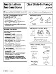
Installation
Instructions
Electric
Drop-In Range
JDS28, JDP39
Questions? Call 800.GE.CARES (800.432.2737) or Visit our Website at: ge.com
• Proper installation is the responsibility of the
installer and product failure due to improper
installation is NOT covered under the warranty.
• NOTE – This appliance must be properly
grounded.
BEFORE YOU BEGIN
Read these instructions carefully and
completely.
•
IMPORTANT
•
IMPORTANT
— Save these
instructions for local inspector’s use.
•
ATTENTION INSTALLER
— Observe all
governing codes and ordinances.
• Note to Installer – Be sure to leave these
instructions with the consumer.
• Note to Consumer – Keep these instructions
for future reference.
All electric drop-in ranges must be hard wired
(direct wired) into an approved junction box.
A plug and receptacle is NOT permitted on
these products.
PARTS INCLUDED
TOOLS YOU WILL NEED
Phillips Screwdriver
1/8” Drill Bit and
Electric or Hand Drill
2 Shoulder Screws
(for stop device)
Lower Trim
2 Screws
Standard Screwdriver
Level
MATERIALS NEEDED
Nut Driver
Tape Measure
Junction Box
Strain Relief Clamp
for 1/2” conduit
Hammer
Wire Nuts
Straight Edge
or Square
Pencil
Safety Glasses
Hand or Sabre Saw
31-10595-2
1-07 JR
1
Installation Instructions
IMPORTANT SAFETY INSTRUCTIONS
FOR YOUR SAFETY
ELECTRICAL REQUIREMENTS
This appliance must be supplied with the
proper voltage and frequency, and connected
to an individual, properly grounded branch
circuit, protected by a circuit breaker or fuse
having amperage as noted on rating plate.
(Rating Plate is located behind the oven
door on the range.)
WARNING: For personal safety,
remove house fuse or open circuit breaker
before beginning installation. Failure to do
so could result in serious injury or death.
• All rough-in and spacing dimensions must be
met for safe use of your range.
• To reduce the risk of burns or fire when
reaching over hot surface elements, cabinet
storage space above the cooktop should be
avoided. If cabinet storage space is to be
provided above the cooktop, the risk can
be reduced by installing a range hood that
protrudes at least 5” beyond the front of
the cabinets. Cabinets installed above the
cooktop must be no deeper than 13”.
Rating
plate location
• Be sure your appliance is properly installed
and grounded by a qualified technician.
We recommend you have the electrical wiring
and hookup of your range connected by a
qualified electrician. After installation, have
the electrician show you where your main
range disconnect is located.
Check with your local utilities for electrical
codes which apply in your area. Failure to
wire your range according to governing codes
could result in a hazardous condition. If there
are no local codes, your range must be wired
and fused to meet the requirements of the
National Electrical Code, ANSI/NFPA No. 70—
Latest Edition. You can get a copy by writing:
National Fire Protection Association
Batterymarch Park
Quincy, MA 02269
Effective January 1, 1996, the National
Electrical Code requires that new, but not
existing, construction utilize a four-conductor
connection to an electric range. When
installing an electric range in new construction,
a mobile home, recreational vehicle or an area
where local codes prohibit grounding through
the neutral conductor, follow the instructions
in the section on NEW CONSTRUCTION
AND FOUR-CONDUCTOR BRANCH CIRCUIT
CONNECTION.
You must use a three-wire, single-phase A.C.
208Y/120 Volt or 240/120 Volt, 60 hertz electrical
system. If you connect to aluminum wiring,
properly installed connectors approved for
use with aluminum wiring must be used.
2
Installation Instructions
PRE-INSTALLATION CHECKLIST
Door removal is not a requirement for
installation of the product, but is an added
convenience. To remove the door:
• Move Range Indoors In Front of Cabinet
Opening
• Protect the kitchen floor! Flatten and place
a piece of the shipping carton in front of the
installation location to protect the flooring.
• Open the oven door as far as it will go.
• Push both hinge
locks down toward
the door frame,
to the unlocked
position. This may
require a flat blade
screwdriver.
• Inspect Installation Location
Inspect cutout dimensions and location
of electrical junction box to be sure it fits
within the layout location. See page 4.
Refer to alternate construction section for
the following non-standard installations.
a. Counter opening extends to the wall:
Maintop Filler Kit (JXS66XX), or
Backguard Kit (JXS32XX).
Hinge
unlocked
position
Hinge
slot
Hinge
arm
DO NOT LIFT THE DOOR
BY THE HANDLE!
WARNING: If you do not use these kits,
the anti-tip bracket must fit under an
attachment to the wall that can withstand
a force of 200 lbs. in the upward direction.
See Step 1 under INSTALL THE RANGE.
• Place hands on both sides of
the door, and close the oven
door to the removal position.
This is half way between the
broil stop and fully closed.
b. Island Installation:
To provide an optimum installation, the
top surface of the countertop must be
level and flat (lie on the same plane)
around the 3 sides that are adjacent to
range cooktop. Proper adjustments to
make the top flat should be made or
gaps between the countertop and range
cooktop may occur. Forcing the cooktop
to fit may cause excessive gaps.
• Lift door up
and out until the
hinge arms clear
the slots.
To obtain Kits:
a. Visit GE Web Site (See page 1)
b. Call GE Answer Center (See page 1)
c. Contact Dealer
Hinge clears slot
NOTE: The oven door is very heavy. Be sure
you have a firm grip before lifting the oven
door off the hinges. Use caution once the door
is removed. Do not lay the door on its handle.
This could cause dents or scratches.
• Remove packing materials. Remove labels
on door, plastic on trims and panel, and
all tape around the range.
3
Installation Instructions
PRE-INSTALLATION CUTOUT AND
REQUIRED CLEARANCES
NOTE: Drop-In Ranges are designed to
hang from the countertop only. Do not
install on a platform or support rails.
If cabinets are placed less than
30” min. above the range, see
alternate construction.
30” ranges conform to U.L.
requirements for 0” spacing
from vertical walls below
countertops. Allow 1/4”
minimum clearance at the
back wall above the countertop.
Wall coverings, counters and
cabinets around range must
withstand heat (up to 200°F)
generated by the range.
4
Installation Instructions
PREPARE TO INSTALL THE RANGE
STANDARD INSTALLATION
Wall
Flat
area
R
1/4” min.
flat
25”
typically
23-3/16”
9/16” min.
flat
1/4”
9/16” min.
flat
Range support
29-15/16”– 30-1/16”
smooth cut
Countertop
Braces secured between the
underside of the countertop and
the cabinet if required to obtain
1-1/4” minimum thickness (two
sides)
The Standard Installation of this Drop-In Range
is to hang by the countertop on the side metal
flanges under cooktop. This Range must not
be installed on a base or sub structure
(2”x 4” support).
If the construction of your cabinet cannot
provide a 1/4” flat area at the back of the
countertop opening, consider changing the
countertop to accommodate this dimension.
5
1
Center the 30” wide opening over the
adjacent cabinets and mark with a straight
edge.
2
Using a straight edge, mark the back line
at 23-3/16” from the front edge of the
counter.
3
Be careful not to damage the adjacent
cabinets while cutting the countertop.
4
Remove countertop raised edge, if
incorporated. (See illustration on page 4.)
Installation Instructions
ELECTRICAL CONNECTIONS
1
Remove house fuse or open circuit
breaker.
2
Loosen screws for the junction box cover
and rotate out of place or remove the
cover.
3
Examine the junction box location to
determine the best routing of the conduit,
and select the best available 7/8” diameter
knockout. Avoid using holes in the top of
the junction box to prevent the conduit
from interfering with the back of the
range.
4
Break open the selected knockout by
placing a bladed screwdriver on the
scored opening in the junction box and
striking the screwdriver with a hammer.
(Pliers may be required to complete the
removal of the knockout.)
WARNING:
Improper connection
of aluminum house wiring to copper leads can
result in an electrical hazard or fire. Use only
connectors designed for joining copper to
aluminum and follow the manufacturer’s
recommended procedure closely.
GENERAL NOTE FOR ALL WIRE NUT
APPLICATIONS: THE PROPER SIZE WIRE NUT
SHALL BE PLACED OVER THE STRIPPED
LEADS AND THE WIRE NUT TWISTED UNTIL
THE WIRE NUT CAN NOT BE PULLED FROM
THE LEADS. NO CONDUCTOR SHALL BE
EXPOSED IN THE CONNECTION. THE
EXCEPTION TO THE CONDUCTOR BEING
EXPOSED IS THE BARE COPPER GROUND
CONNECTION.
BREAKER OR FUSE SIZE
240V
40 Amps +
208V
40 Amps +
+ NOTE: Check Local Codes for
required breaker size.
7/8” knockout
Cover rotated from
box opening
5
Position the range in front of the opening,
but slightly to the side, in a manner so
that a person can enter the opening to
wire the range to the house wiring in
the junction box.
6
Feed wires and conduit through the open
hole and snap the conduit fitting into the
hole. Route the conduit in a manner that
will not interfere with the rear wire cover.
The conduit must be routed below the
wire cover.
6
Installation Instructions
NEW CONSTRUCTION AND
FOUR-CONDUCTOR BRANCH
CIRCUIT CONNECTION
THREE-CONDUCTOR BRANCH
CIRCUIT CONNECTION
When connecting to a 3-conductor branch
circuit, if local codes permit:
7a
Connect the bare oven ground conductor
with the crimped neutral (white) lead to
the branch circuit neutral (white or gray
in color), using wire nuts.
7b
Connect the oven red lead to the branch
circuit red lead, and the oven black lead to
the branch circuit black lead in accordance
with local codes, using wire nuts. If the
residence red, black or white leads are
aluminum conductors, see “WARNING”
note (see page 6).
• When installing in new construction, or
• When installing oven in a mobile home or
recreational vehicle, or
• When local codes do not permit grounding
through neutral:
Black
Ground and
neutral wires
(white)
Cut the neutral (white) lead from the
crimp. Re-strip the neutral (white) lead to
expose the proper length of conductor
and connect it to the white or gray branch
circuit neutral in accordance with local
code using wire nuts.
7b
Attach the appliance grounding lead
(green or bare copper) in accordance with
local codes. If the residence grounding
conductor is aluminum, see WARNING
note (see page 6).
7c
Connect the oven red lead to the branch
circuit red lead and the oven black lead to
the branch circuit black lead in accordance
with local codes, using wire nuts. If the
residence red, black or white leads are
aluminum conductors, see “WARNING”
note (see page 6).
Branch
circuit
Range conduit
snaps into box
Red
7a
Alternate
knockout
Black
Neutral bare wire
connection
Branch
circuit
Range conduit
snaps into box
Ground
wires
Red
White
7
Alternate
knockout
Installation Instructions
ELECTRICAL CONNECTIONS
8
(CONT.)
Reinstall Junction box cover.
Do not shorten the flexible conduit. The conduit strain relief clamp must be securely attached to
the junction box and the flexible conduit must be securely attached to the clamp. If the flexible
conduit will not fit within the junction box, do not install the oven until a clamp of the proper
size is obtained.
NOTE TO ELECTRICIAN: The 3 power leads supplied with this appliance are UL recognized
for connection to larger gauge household wiring. The insulation of these 3 leads is rated at
temperatures much higher than the temperature rating of household wiring. The current carrying
capacity of the conductor is governed by the temperature rating of the insulation around the wire,
rather than the wire gauge alone.
8
Installation Instructions
INSTALL THE RANGE
1 INSTALLING THE ANTI-TIP
BRACKET
Select the proper position for the countertop
thickness and move bracket to proper position.
(Unit is supplied with bracket in position 1.)
The anti-tip bracket is attached to the back of
the Drop-In Range. It is designed to fit under
the bottom of the countertop opening at the
rear. Measure counter thickness at back of
cutout to determine correct bracket location.
1 For 3/4” Counter
4 For 3.5”
2 For 1.18” (3 cm) Counter 5 Alternate
(shown below)
3 For 1.5” Counter
Anti-tip bracket location
(rear of range)
Cooktop
ANTI-TIP INSTALLATION
Interior wall
1/4” min. flat area
Wall stud
Maintop
Countertop
thickness
Anti-tip
bracket
Bottom of
countertop
Bottom of
countertop
to engage
bracket by
1/2” min.
ALTERNATE
ANTI-TIP INSTALLATION
Wire cover
Interior wall
Non-kit application
Maintop
Attachment
Wall stud
Countertop
surface
10-3/8”
Wire
cover
1-1/2”
Position #5
non-kit
application
Anti-tip bracket
*Attachment
to engage
bracket by 1/2” min.
9
Attachment
anchored to
wall stud is
required
Installation Instructions
INSTALL THE RANGE
(CONT.)
2 INSTALL STOP SCREW
3 PLACING THE RANGE INTO
THE OPENING
These screws prevent the range from sliding
out of position during operation.
It is suggested that two people lift the range
into place, carefully setting the side metal
flanges on the edges of the countertop
opening. Carefully slide the range toward the
back of the opening. In the last 1” of travel, lift
the front of the range approx. 1/2” to clear the
stop screws located in the sides of the cabinet
and slide the range until the range is seated.
Lower front of the range onto countertop.
Lift and slide
range on
countertop
Countertop
Carefully mark the cabinet for the location of
the stop screws. Drill 1/8” pilot holes into the
cabinet, each side of the range. (Make sure
not to drill entirely through the cabinet wall.)
Carefully turn the shoulder screws into the
pilot holes until they are tight.
Range
Cabinet
Countertop
Make sure the edge
of the countertop
fits flush against
the end of the
Front Control Panel
10
Installation Instructions
4 CHECK FOR PROPER
INSTALLATION OF THE
STOP SCREW
5 ATTACH THE LOWER TRIM
Attach the lower trim (supplied separately with
the range) to the bottom of the vertical side
trim with the 2 screws supplied.
Look at both sides of the range under the door.
The stop screws must be located in the notch
on the sides of the range, and not touch the
top of the notch when the range is fully seated
on the countertop. If the screws do not meet
the requirements, move the screws to a
position that meets these requirements.
(See illustration below.)
Lower
left
corner
front
frame
Side
trim
End flange
& tab on
lower trim
fits inside
side trim
Notch in bottom
of side trim
Clear
Attach
1 screw
each side
Top flange
1/2” wide
Side
trim
Lower
trim
Shoulder
screw
11
Installation Instructions
INSTALL THE RANGE
(CONT.)
REPLACING THE OVEN DOOR
9
NOTE: The oven door is heavy. You may need
help lifting the door high enough to slide it
into the hinge slots. Do not lift the door by
the handle.
6
Hinge in
locked position
Lift the oven door by
placing one hand on
each side. The door is
heavy, so you may need
help. Do not lift the door
by the handle.
Notch of hinge
securely fitted
into bottom of
hinge slot
10
7
With the door at the same angle as the
removal position (halfway between the
closed and broil stop position, seat the
notch of the hinge arm into the bottom
edge of the hinge slot. The notch of the
hinge arm must be fully seated into the
bottom of the slot.
Close the oven door.
11 CHECK FOR PROPER
INSTALLATION OF
ANTI-TIP BRACKET
Lower the oven door and gently apply medium
force at the handle end until movement of the
range is detected. Continue pressing until the
anti-tip bracket is engaged and movement
stops. A small amount of movement is
acceptable at the back of the range top, but it
should be stable and not tip once the anti-tip
bracket is engaged.
Hinge arm
Bottom edge
of slot
Hinge notch
8
Push the hinge locks up against the front
frame of the oven cavity, to the locked
position.
Open the oven door as far as it will open.
12
Installation Instructions
12 FINAL CHECKLIST
• Check to make sure the circuit breaker is closed (Reset) or the circuit fuses are replaced.
• Be sure power is in service to the building.
• Check to be sure that all packing materials and tape on metal panel (if applicable) under control
knobs and drawer have been removed.
13 OPERATION CHECKLIST
• Check to make sure the Clock display is energized. If a series of horizontal red lines appear in
the display, disconnect power immediately. Recheck the range wiring connections. If change is
made to connections, retest again. If no change is required, have building wiring checked for
proper connections and voltage. It is recommended that the clock be changed if the red lines
appear.
• Push down and turn any one of the four surface knobs to “MED” setting to observe that the
element glows within 15 seconds. Turn the knob off when glow is detected. If the glow is not
detected within the time limit, recheck the range wiring connections. If change is required,
retest again. If no change is required, have building wiring checked for proper connections
and voltage.
13
Installation Instructions
ALTERNATE CONSTRUCTION PREPARATION
A OPTIONAL MAINTOP FILLER OR
BACKGUARD KIT
B ISLAND INSTALLATION
When installing in an island or other
non-standard location, countertop cutout
dimensions must be according to page 5.
If counter opening extends to the wall, it will
require Maintop Filler Kit (JXS66XX) or
Backguard Kit (JXS32XX) to close the gap.
For the anti-tip bracket instructions, see
page 9.
NOTE: If the countertop is greater than 25”,
it will show a gap between the backguard
and wall or between filler kit and the wall.
In this application, do not use Backguard Kit
(JXS32XX).
If the countertop is less than 25”, a gap will
occur between the countertop front and the
control panel ends. (See page 10, Step 3).
C CABINETS OVER THE RANGE
LESS THAN 30”
Wall
25”
Must be
level
9/16”
9/16”
Must be
flat
If a 30” clearance between cooking surface
and overhead combustible material or metal
cabinets cannot be maintained, protect the
underside of the cabinets above the cooktop
with not less than 1/4” insulating millboard
covered with sheet metal not less than 0.0122”
thick.
30”
smooth cut
D CABINET CUTOUT HEIGHT
MORE THAN 27-1/2” USE
LOWER TRIM KIT
Must be
flat
Must be level
Optional Lower Trim to fill space beneath
27-1/2” min. requirement (see page 4).
Use lower Trim Kit JXS96XX.
Refer to the Filler or Backguard Kit instructions
for Installation details.
14
Notes
15
Notes
16
Printed in the United States